645-053, REV. 5/18
Hydraulic Hazards
DANGER
Small hydraulic hose leaks are extremely
dangerous, and can inject hydraulic oil
under the skin, even through gloves.
Infection and gangrene are possible when
hydraulic oil penetrates the skin. See a
doctor immediately to prevent loss of limb
or death.
• Wear personal protective equipment, such as gloves
and safety glasses, whenever servicing or checking
a hydraulic system.
• Assume that all hydraulic hoses and components are
pressurized. Relieve all hydraulic pressure before
disconnecting any hydraulic line.
• Never try to stop or check for a hydraulic leak with any
part of your body; use a piece of cardboard to check
for hydraulic leaks.
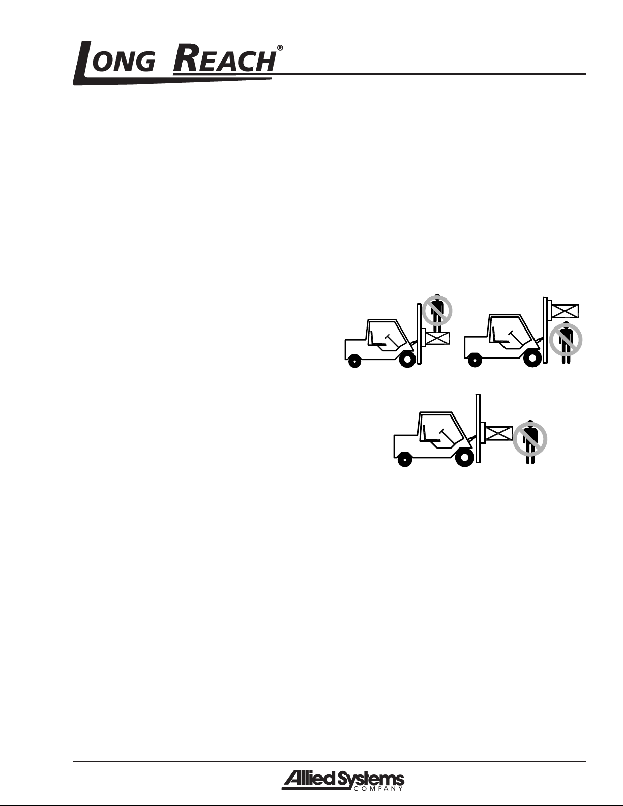
Electrical Hazards
WARNING
Remain at least 25 feet from high voltage
electrical wires. Failure to do so may
result in injury or death and will damage
equipment.
• All electrical cables and connectors must be in good
condition (free of corrosion, damage, etc). Use cau-
tion in wet weather to avoid danger from electrical
shock. Never attempt electrical testing or repair while
standing in water.
• Do not wear electrically conductive jewelry, clothing,
or other items while working on the electrical system.
Maintenance Warnings
Maintenance, lubrication and repair of this machine can
be dangerous unless performed properly.You must have
the necessary skills and information, proper tools and
equipment. Work in a method that is safe, correct, and
meets your company’s requirements.
• Do not attempt to make adjustments, or perform
maintenance or service unless you are authorized
and qualified to do so.
• Include attachments in a scheduled maintenance and
inspection program. Tailor inspection steps to the at-
tachment.
• Unless specified in service procedures, never attempt
maintenance or lubrication procedures while the ma-
chine is moving or the engine is running.
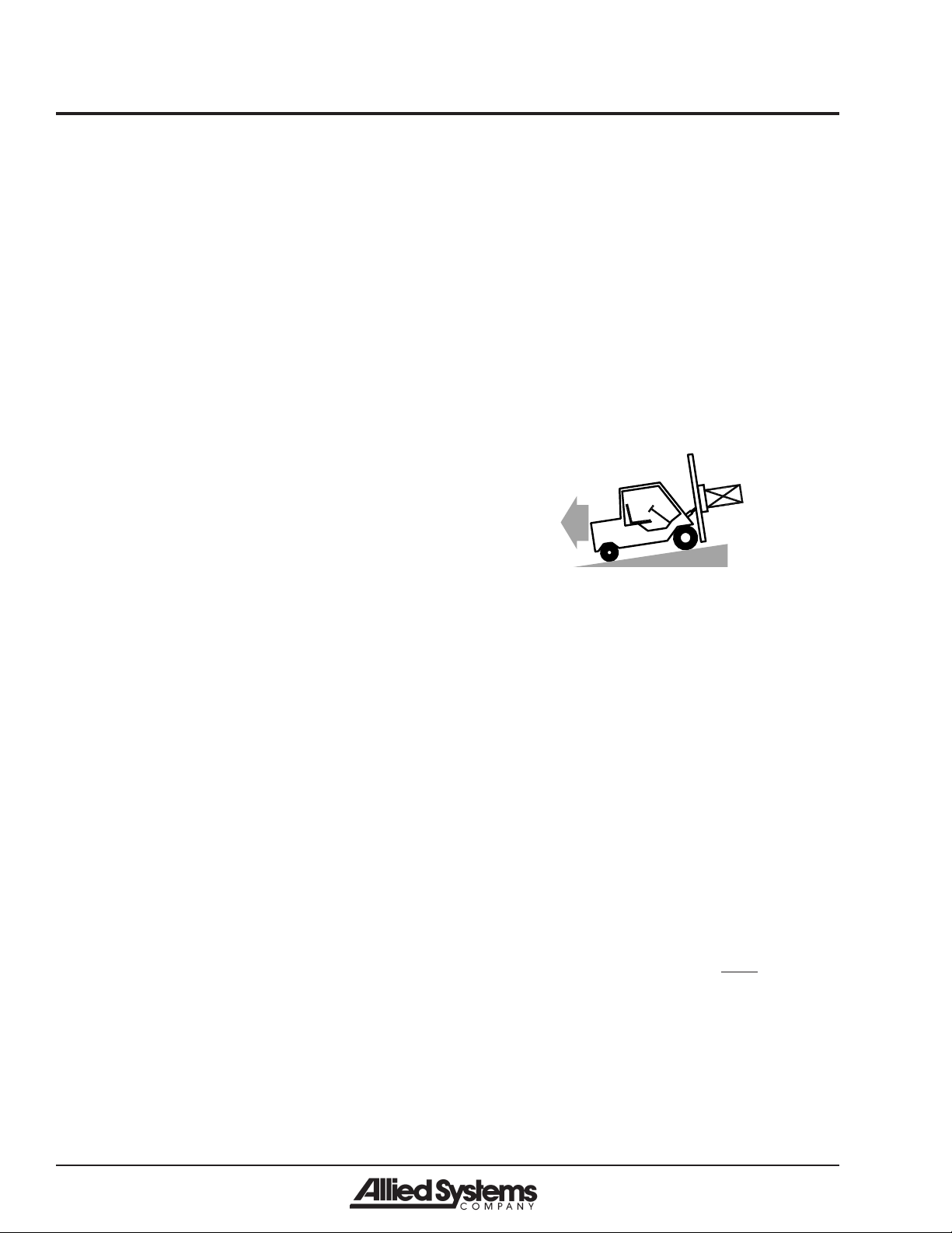
• Always perform all maintenance and lubrication pro-
cedures with the machine on level ground, parked
away from traffic lanes.
Notice
Local laws and regulations may require
that additional safety measures be taken.
• Never rely on the hydraulic system to support any
part of the machine during maintenance or lubrication.
Never stand under a component that is supported
only by the hydraulics. Make sure it is resting on its
mechanical stops or appropriate safety stands.
• Use caution when working around hot fluids. Always
allow lubricating and hydraulic oils to cool before
draining. Burns can be severe.
• Use extreme caution when using compressed air to
blow parts dry. The pressure should not exceed 30
psi (208 kPa) at the nozzle. Never use compressed
air on yourself. Air pressure penetrating your skin
can be fatal.
• Engine exhaust fumes can cause death. If it is neces-
sary to run the engine in an enclosed space, remove
the exhaust fumes from the area with an exhaust pipe
extension. Use ventilation fans and open shop doors
to provide adequate ventilation.
• Before disconnecting hydraulic lines, be sure to lower
all loads and relieve all hydraulic pressure. The load
could fall on you, or escaping hydraulic oil could cause
severe personal injury.
• Prevent personal injury or equipment damage by us-
ing a lifting device with a lifting capacity greater than
twice the weight of any equipment to be lifted.