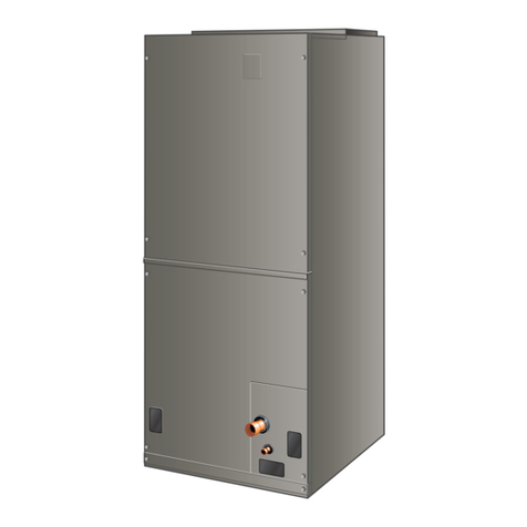
Allied 4SCU16LE User manual

508219-01 Issue 2132 Page 1 of 43
SERVICE MANUAL
4SCU16LE/14LB
(P) 508219-01
*P508219-01*
Table of Contents
Technical Specications - 4SCU16LE .........................2
Technical Specications - 4SCU14LB .........................5
Technical Specications - 4SCU14LE-7......................8
Technical Specications - 4SCU14LB-7....................10
Technical Specications - 4SCU14LE-4....................12
Refrigerant Metering Device - Indoor Coil .................16
Installation .................................................................16
Refrigeration Piping...................................................19
Electrical Wiring.........................................................28
Sequence of Operation..............................................32
Start-Up .....................................................................32
Maintenance..............................................................33
Wiring Diagram..........................................................34
Servicing Units Void of Charge..................................38
System Refrigerant....................................................38
Charge Labels ...........................................................41
Start-Up and Performance Checklist.........................43
This is a safety alert symbol and should never be ignored. When you see this symbol on labels or in manuals, be alert to
the potential for personal injury or death.
Electric shock hazard.
Can cause injury or death. Before attempting
to perform any service or maintenance,
turn the electrical power to unit OFF at
disconnect switch(es). Unit may have
multiple power supplies.
WARNING
As with any mechanical equipment, contact with sharp
sheet metal edges can result in personal injury. Take
care while handling this equipment and wear gloves
and protective clothing.
CAUTION
Improper installation, adjustment, alteration, service
or maintenance can cause property damage, personal
injury or loss of life. Installation and service must be
performed by a licensed professional HVAC installer (or
equivalent), service agency or the gas supplier.
WARNING

508219-01Issue 2132Page 2 of 43
Technical Specications - 4SCU16LE
MODEL NUMBER GUIDE
PHYSICAL AND ELECTRICAL DATA
Model Voltage/Hz/Phase Voltage
Range
Min.
Circuit
Amp.
Max. Over
Current
Device
(amps)
Compressor Fan Motor
Rated
Load
(amps)
Locked
Rotor
(amps)
Rated
Load
(amps)
Rated HP Nom.
RPM
4SCU16LE118P-50 208-230/60/1 197-253 11.9 20 9.0 48 0.7 1/10 1075
4SCU16LE124P-50 208-230/60/1 197-253 14.6 25 10.9 52 1.0 1/6 825
4SCU16LE130P-50 208-230/60/1 197-253 17.0 25 12.8 63 1.0 1/6 825
4SCU16LE136P-50 208-230/60/1 197-253 18.0 30 13.6 79 1.0 1/6 825
4SCU16LE141P-50 208-230/60/1 197-253 19.3 30 14.7 75 1.0 1/6 825
4SCU16LE142P-50 208-230/60/1 197-253 23.4 40 17.9 112 1.0 1/6 825
4SCU16LE147P-50 208-230/60/1 197-253 22.9 35 16.9 94 1.8 1/3 825
4SCU16LE148P-50 208-230/60/1 197-253 24.2 40 18.0 94 1.7 1/4 825
4SCU16LE159P-50 208-230/60/1 197-253 28.8 45 20.8 127 2.8 1/3 V Spd
4SCU16LE160P-50 208-230/60/1 197-253 29.6 50 22.2 128 1.8 1/3 825
UNIT DIMENSIONS (IN.)
Model No.
Dimensions Shipping
Weight
(lbs.)
A - width B - depth C - Height
4SCU16LE118P-50 24.75 26.75 29.75 155
4SCU16LE124P-50 29.38 31.25 29.75 171
4SCU16LE130P-50 29.38 31.25 37.75 187
4SCU16LE136P-50 29.38 31.25 29.75 205
4SCU16LE141P-50 29.38 31.25 37.75 227
4SCU16LE142P-50 29.38 31.25 37.75 234
4SCU16LE147P-50 35.75 37.75 33.75 272
4SCU16LE148P-50 29.38 31.25 37.75 255
4SCU16LE159P-50 35.75 37.75 43.75 284
4SCU16LE160P-50 35.75 37.75 43.75 284
Note:
Weights listed are unit weights with packaging
Dimensions listed are unit sizes w/o packaging
Minor Revision Code
Major Revision Code
50 = Omniguard®
Electrical
P - 208 - 230v/60hz/1Ph
Tonnage
18, 24, 30, 36, 41, 42, 47, 48, 59, 60
Region Restriction
1 = all Regions
Refrigerant
4 = R410A
SCU
Split Air Conditioner
SEER
16
Tier
LE = Louvered Enhanced
4 SCU 16 LE 1 24 P - 50 A

508219-01 Issue 2132 Page 3 of 43
SOUND RATINGS
Model Sound Power1
Estimated Sound Pressure (dBA)2
Approximate Distance3
3.3 Feet
(1 Meter)
6.6 Feet
(2 Meters)
9.8 Feet
(3 Meters)
4SCU16LE118P-50
70 62 56 52
4SCU16LE124P-50
77 69 63 59
4SCU16LE130P-50
75 67 61 57
4SCU16LE136P-50
78 70 64 60
4SCU16LE141P-50
74 66 60 56
4SCU16LE142P-50
77 69 63 59
4SCU16LE147P-50
79 71 65 61
4SCU16LE148P-50
76 68 62 58
4SCU16LE159P-50
77 69 63 59
4SCU16LE160P-50
78 70 64 60
1 Rated in accordance with AHRI standard 270 (2015). AHRI Standard 270 establishes a method of rating outdoor unitary equipment in terms of
Sound Power.
2 Rated in accordance with AHRI standard 275 (2010). AHRI Standard 275 provides the calculations for estimating the A-Weighted Sound Pressure
at a given distance from the equipment. That is a more useful number because that is what humans will hear.
3 Based only on distance factor; other factors may change this value such as:
- Unit location (reective surfaces adjacent to the unit)
- Barrier shielding sources
- Sound path/elevation
- Outside noise sources
ACCESSORIES
System Accessory Where Used Kit Number Purpose
Liquid Line solenoid All models 60M52 Prevents liquid migration to the compressor especially for high liquid riser
applications
Low ambient (cooling operation) All models 34M72 Enables cooling demand down to 30 °F. Will require freeze stat, CC heater and
TXV
Compressor Short Cycle Protector All models 47J27 Delays compressor start 5-7 minutes to prevent short cycling
Hard Start 18 10J42 Scroll compressors usually do not require hard start; maybe needed for utility
brown-out or low voltage areas
Hard Start 24 thru 60 88M91
Crankcase Heater 18, 24, 30, 36 93M04
Prevents liquid migration to compressor in cold weatherCrankcase Heater 41, 42 93M05
Crankcase Heater 47, 48, 59, 60 Factory Installed
Sound Cover Factory Installed Lowers compressor sound level
Loss of Charge Kit Factory Installed Protects the compressor if refrigerant charge is too low
Additional System Accessories (indoor section)
TXV Kit
18, 24, 30 H4TXV01
TXVs provide superior refrigerant ow control, comfort and eciency compared
to pistons
36, 41, 42, 47, 48 H4TXV02
59, 60 H4TXV03
Outdoor Thermostat - electric heat All models 10Z23 Prevents electric heat operation above specic ambient conditions
Outdoor Thermostat - Mounting box All models 31461 Mounting box for outdoor thermostat
Freezestat All models 93G35 Protects the compressor at low suction pressure conditions
Overow switch All models 11U75 Turn the system o, if condensate water overows due to clogged drain pipes
Blower time delay All models 58M81 Improves system eciency and comfort
Single point power supply All models 21H39 Provide single power source in one junction box
Auxiliary blower relay All models 85W66 Maybe required to select multiple indoor blower speeds

508219-01Issue 2132Page 4 of 43
REFRIGERATION DATA
Outdoor Model Charge
(oz) 6
Refrigerant Connection
Refrigerant Line Size Indoor Expansion
Device
Outdoor Indoor (DTC) 7
Suction Liquid Suction Liquid Suction Liquid Piston TXV 1
4SCU16LE118P-50 73 3/4 3/8 3/4 3/8 3/4 3/8 0.052 H4TXV01
4SCU16LE124P-50 73 3/4 3/8 3/4 3/8 3/4 3/8 0.06 H4TXV01
4SCU16LE130P-50 100 3/4 3/8 3/4 3/8 3/4 3/8 0.067 H4TXV01
4SCU16LE136P-50 113 7/8 3/8 7/8 3/8 7/8 3/8 0.072 H4TXV02
4SCU16LE141P-50 144 7/8 3/8 7/8 3/8 7/8 3/8 † H4TXV02
4SCU16LE142P-50 140 7/8 3/8 7/8 3/8 7/8 3/8 0.081 H4TXV02
4SCU16LE147P-50 176 7/8 3/8 7/8 3/8 7/8 3/8 † H4TXV02
4SCU16LE148P-50 156 7/8 3/8 7/8 3/8 7/8 3/8 0.083 H4TXV02
4SCU16LE159P-50 192 7/8** 3/8 7/8 3/8 1-1/8 3/8 † H4TXV03
4SCU16LE160P-50 192 7/8** 3/8 7/8 3/8 1-1/8 3/8 0.097 H4TXV03
*Factory charged for 15 feet of line set
** Adapter shipped with unit
† TXV only
COOLING PERFORMANCE WITH DTC1
Outdoor Model Indoor Model Capacity
(BTUH) EER SEER
4SCU16LE118P-50 EAC4X24B 18,000 12.20 14.00
4SCU16LE124P-50 EAC4X24B 24,000 12.20 14.25
4SCU16LE130P-50 EAC4X30B 28,400 12.20 14.25
4SCU16LE136P-50 EAC4X36B 34,200 12.20 14.50
4SCU16LE141P-50 EAC4X49C 38,000 12.20 15.10
4SCU16LE142P-50 EAC4X49C 40,000 12.20 14.25
4SCU16LE147P-50 EAC4X60C 46,000 12.20 14.50
4SCU16LE148P-50 EAC4X60C 46,000 12.20 14.25
4SCU16LE159P-50 EAC4X60C 57,500 12.00 14.25
4SCU16LE160P-50 EAC4X60C 57,000 11.70 14.00
1 DTC = Designated Tested Combination
NOTE:
For the latest ratings, please see
www.alliedratings.com or www.AHRIdirectory.org

508219-01 Issue 2132 Page 5 of 43
MODEL NUMBER GUIDE
Minor Revision Code
Major Revision Code
50 = Omniguard®
Electrical
P = 208 - 230v/60hz/1Ph
Tonnage
18, 24, 30, 36, 42, 48, 60
Region Restrictions
1 = All Regions
Refrigerant
4 = R410A
SCU
Split Air Conditioner
SEER
14
Tier
LB = Louvered Basic
4 SCU 14 LB 1 24 P - 50 A
PHYSICAL AND ELECTRICAL DATA
Model Voltage/Hz/
Phase
Voltage
Range
Min.
Circuit
Amp.
Max. Over
Current
Device
(amps)
Compressor Outdoor Fan Motor
Rated
Load
(amps)
Locked
Rotor
(amps)
Rated
Load
(amps)
Rated
HP
Nom.
RPM
4SCU14LB118P-50 208-230/60/1 197-253 11.9 20 9.0 48 0.7 1/10 1075
4SCU14LB124P-50 208-230/60/1 197-253 14.6 25 10.9 52 1.0 1/6 825
4SCU14LB130P-50 208-230/60/1 197-253 17.0 25 12.8 63 1.0 1/6 825
4SCU14LB136P-50 208-230/60/1 197-253 18.0 30 13.6 79 1.0 1/6 825
4SCU14LB142P-50 208-230/60/1 197-253 23.4 40 17.9 112 1.0 1/6 825
4SCU14LB148P-50 208-230/60/1 197-253 24.2 40 18.0 94 1.7 1/4 825
4SCU14LB160P-50 208-230/60/1 197-253 29.6 50 22.2 128 1.8 1/3 825
UNIT DIMENSIONS (IN.)
Model
Dimensions (inch) Shipping
Weight
(lbs.)
A - Width B - Depth C - Height
4SCU14LB118P-50 24.75 26.75 29.75 155
4SCU14LB124P-50 29.38 31.25 29.75 171
4SCU14LB130P-50 29.38 31.25 37.75 187
4SCU14LB136P-50 29.38 31.25 29.75 205
4SCU14LB142P-50 29.38 31.25 37.75 234
4SCU14LB148P-50 29.38 31.25 37.75 255
4SCU14LB160P-50 35.75 37.75 43.75 284
Note:
Dimensions listed are unit sizes w/o packaging
Weights listed are units weights with packaging.
Technical Specications - 4SCU14LB

508219-01Issue 2132Page 6 of 43
ACCESSORIES
System Accessory Where Used Kit Number Purpose
Liquid Line solenoid All models 60M52 Prevents liquid migration to the compressor especially for high liquid riser applications
Low ambient (cooling operation) All models 34M72 Enables cooling demand down to 30 °F. Will require freeze stat, CC heater and TXV
Compressor Short Cycle protector All models 47J27 Delays compressor start 5-7 minutes to prevent short cycling
Hard Start
18 10J42 Scroll compressors usually do not require hard start; maybe needed for utility brown-
out or low voltage areas
24 thru 60 88M91
Crankcase Heater
18, 24, 30, 36 93M04
Prevents liquid migration to compressor in cold weather
42 93M05
48, 60 Factory
Installed
Sound Cover
18, 24, 30, 36 14W00
Lowers compressor sound level
42, 48, 60 14W01
Loss of Charge Kit All models 84M23 Protects the compressor if refrigerant charge is too low
Additional System Accessories (indoor section)
TXV Kit
18, 24, 30 H4TXV01
TXVs provide superior refrigerant ow control, comfort and eciency compared to
pistons
36, 42, 48 H4TXV02
60 H4TXV03
Outdoor Thermostat - electric heat All models 10Z23 Prevents electric heat operation above specic ambient conditions
Outdoor Thermostat - mounting box All models 31461 Mounting box for outdoor thermostat
Freezestat All models 93G35 Protects the compressor at low suction pressure conditions
Overow switch All models 11U75 Turn the system o, if condensate water overows due to clogged drain pipes
Blower time delay All models 58M81 Improves system eciency and comfort
Single point power supply All models 21H39 Provide single power source in one junction box
Auxiliary blower relay All models 85W66 Maybe required to select multiple indoor blower speeds
SOUND RATINGS
Model Sound Power1
Estimated Sound Pressure (dBA)2
Approximate Distance3
3.3 Feet
(1 Meter)
6.6 Feet
(2 Meters)
9.8 Feet
(3 Meters)
4SCU14LB118P-50 72 64 58 54
4SCU14LB124P-50 78 70 64 60
4SCU14LB130P-50 76 68 62 58
4SCU14LB136P-50 78 70 64 60
4SCU14LB142P-50 78 70 64 60
4SCU14LB148P-50 77 69 63 59
4SCU14LB160P-50 78 70 64 60
1 Rated in accordance with AHRI standard 270 (2015). AHRI Standard 270 establishes a method of rating outdoor unitary equipment in terms of
Sound Power.
2 Rated in accordance with AHRI standard 275 (2010). AHRI Standard 275 provides the calculations for estimating the A-Weighted Sound Pressure
at a given distance from the equipment. That is a more useful number because that is what humans will hear.
3 Based only on distance factor; other factors may change this value such as:
- Unit location (reective surfaces adjacent to the unit)
- Barrier shielding sources
- Sound path/elevation
- Outside noise sources

508219-01 Issue 2132 Page 7 of 43
REFRIGERATION DATA
Outdoor Model Charge
(oz) 6
Refrigerant Connection
Refrigerant Line Size Indoor Expansion
Device
Outdoor Indoor (DTC) 7
Suction Liquid Suction Liquid Suction Liquid Piston TXV 1
4SCU14LB118P-50 73 3/4 3/8 3/4 3/8 3/4 3/8 0.052 H4TXV01
4SCU14LB124P-50 73 3/4 3/8 3/4 3/8 3/4 3/8 0.060 H4TXV01
4SCU14LB130P-50 100 3/4 3/8 3/4 3/8 3/4 3/8 0.067 H4TXV01
4SCU14LB136P-50 113 7/8 3/8 7/8 3/8 7/8 3/8 0.072 H4TXV02
4SCU14LB142P-50 140 7/8 3/8 7/8 3/8 7/8 3/8 0.081 H4TXV02
4SCU14LB148P-50 156 7/8 3/8 7/8 3/8 7/8 3/8 0.083 H4TXV02
4SCU14LB160P-50 192 7/8** 3/8 7/8 3/8 1-1/8 3/8 0.097 H4TXV03
* Factory charged for 15 feet of line set
** Adapter shipped with unit
COOLING PERFORMANCE WITH DTC1
Outdoor Model Indoor Model Capacity
(BTUH) EER SEER
4SCU14LB118P-50 EAC4X24B 18,000 12.20 14.00
4SCU14LB124P-50 EAC4X24B 24,000 12.20 14.25
4SCU14LB130P-50 EAC4X30B 28,400 12.20 14.25
4SCU14LB136P-50 EAC4X36B 34,200 12.20 14.50
4SCU14LB142P-50 EAC4X49C 40,000 12.20 14.25
4SCU14LB148P-50 EAC4X60C 46,000 12.20 14.25
4SCU14LB160P-50 EAC4X60C 57,000 11.70 14.00
1 DTC = Designated Tested Combination
NOTE:
For the latest ratings, please see
www.alliedratings.com or www.AHRIdirectory.org

508219-01Issue 2132Page 8 of 43
Technical Specications - 4SCU14LE-7
MODEL NUMBER GUIDE
PHYSICAL AND ELECTRICAL DATA
Model Voltage/Hz/
Phase
Voltage
Range
Min.
Circuit
Amp.
Max. Over
Current
Device
(amps)
Compressor Fan Motor
Refrig.
Charge+
(oz.)
Shipping
Weight
(lbs.)
Rated
Load
(amps)
Locked
Rotor
(amps)
Rated
Load
(amps)
Rated
HP
Nom.
RPM
4SCU14LE*18P-7 208-230/60/1 197-253 12.4 20 9.4 56.6 0.7 1/10 1075 77 150
4SCU14LE*24P-7 208-230/60/1 197-253 15.0 25 11.2 60.8 1.0 1/6 825 86 160
4SCU14LE*30P-7 208-230/60/1 197-253 17.0 25 12.8 67.8 1.0 1/6 825 100 180
4SCU14LE*36P-7 208-230/60/1 197-253 18.6 30 14.1 83.0 1.0 1/6 825 102 185
4SCU14LE*42P-7 208-230/60/1 197-253 24.1 40 17.9 113.0 1.7 1/4 825 160 208
4SCU14LE141P-7 208-230/60/1 197-253 22.6 35 16.7 79.0 1.7 1/4 825 161 210
4SCU14LE147P-7 208-230/60/1 197-253 26.7 45 19.9 109.0 1.8 1/3 825 179 251
4SCU14LE148P-7 208-230/60/1 197-253 26.6 45 19.8 109.0 1.7 1/4 825 174 220
4SCU14LE159P-7 208-230/60/1 197-253 34.1 50 25.0 134 2.8 1/3 825 178 235
4SCU14LE160P-7 208-230/60/1 197-253 34.8 60 26.4 134 1.8 1/3 825 192 253
Note:
Weights listed are unit weights with packaging
+ Factory charged for 15 feet oine set. Adjust per installation instructions.
Minor Revision Code
Major Revision Code
Electrical
P - 208 - 230v/60hz/1Ph
Tonnage
18, 24, 30, 36, 42, 48, 60
Region Restriction
1 = all Regions
R = Region-restricted model; not for
installation in the Southwest region
Refrigerant
4 = R410A
SCU
Split Air Conditioner
SEER
14
Tier
LE = Louvered Enhanced
4 SCU 14 LE 1 24 P - 7 A

508219-01 Issue 2132 Page 9 of 43
ACCESSORIES
Description Where Used Kit Number
Crankcase Heater 18, 24, 30, 36 93M04
Hard Start
18 10J42
24, 30, 36, 42, 48, 60 88M91
Compressor Low Ambient All 34M72
Short Cycle Protector All 47J27
Freezestat
3/8 tubing 93G35
5/8 tubing 50A93
Time Delay Relay All 58M81
Loss of Charge Kit All 84M23 (factory installed)
Sound Blanket
18, 24, 30, 36, 41 14W00 (factory installed)
42, 47, 48, 59, 60 14W01 (factory installed)
TXV Kit
18, 24, 30 A4TXV01
36, 42, 48, 60 A4TXV02
UNIT DIMENSIONS (IN.)
Model No.
Dimensions Sound
Rating
(dBA)
A -
Width
B -
Depth
C -
Height
4SCU14LE*18P-7 24.75 26.75 29.75 71
4SCU14LE*24P-7 29.38 31.25 29.75 76
4SCU14LE*30P-7 29.38 31.25 37.75 74
4SCU14LE*36P-7 29.38 31.25 37.75 74
4SCU14LE*42P-7 29.38 31.25 33.75 76
4SCU14LE141P-7 29.38 31.25 37.75 76
4SCU14LE147P-7 29.38 31.25 37.75 80
4SCU14LE148P-7 29.38 31.25 33.75 80
4SCU14LE159P-7 35.75 37.75 37.75 78
4SCU14LE160P-7 35.75 37.75 37.75 80
Note:
Dimensions listed are unit sizes w/o packaging

508219-01Issue 2132Page 10 of 43
Technical Specications - 4SCU14LB-7
MODEL NUMBER GUIDE
Minor Revision Code
Major Revision Code
Electrical
P - 208 - 230v/60hz/1Ph
Tonnage
18, 24, 30, 36, 42, 48, 60
Region Restriction
1 = all Regions
R = Region-restricted model; not for
installation in the Southwest region
Refrigerant
4 = R410A
SCU
Split Air Conditioner
SEER
14
Tier
LB = Louvered Basic
4 SCU 14 LB 1 24 P - 7 A
PHYSICAL AND ELECTRICAL DATA
Model Voltage/Hz/
Phase
Voltage
Range
Min.
Circuit
Amp.
Max. Over
Current
Device
(amps)
Compressor Fan Motor
Refrig.
Charge+
(oz.)
Shipping
Weight
(lbs.)
Rated
Load
(amps)
Locked
Rotor
(amps)
Rated
Load
(amps)
Rated
HP
Nom.
RPM
4SCU14LB*18P-7 208-230/60/1 197-253 12.4 20 9.4 56.6 0.7 1/10 1075 77 150
4SCU14LB*24P-7 208-230/60/1 197-253 15.0 25 11.2 60.8 1.0 1/6 825 86 160
4SCU14LB*30P-7 208-230/60/1 197-253 17.0 25 12.8 67.8 1.0 1/6 825 100 180
4SCU14LB*36P-7 208-230/60/1 197-253 18.6 30 14.1 83.0 1.0 1/6 825 102 185
4SCU14LB*42P-7 208-230/60/1 197-253 24.1 40 17.9 113.0 1.7 1/4 825 160 208
4SCU14LB148P-4 208-230/60/1 197-253 22.6 45 19.8 109.0 1.7 1/4 825 174 220
4SCU14LB160P-4 208-230/60/1 197-253 34.8 60 26.4 134.0 1.8 1/3 825 192 253
Note:
Weights listed are unit weights with packaging
+ Factory charged for 15 feet oine set. Adjust per installation instructions.

508219-01 Issue 2132 Page 11 of 43
ACCESSORIES
Description Where Used Kit Number
Crankcase Heater All 93M04
Hard Start
18 10J42
24, 30, 36, 42, 48, 60 88M91
Compressor Low Ambient All 34M72
Short Cycle Protector All 47J27
Freezestat
3/8 tubing 93G35
5/8 tubing 50A93
Time Delay Relay All 58M81
Loss of Charge Kit All 84M23 (factory installed)
Sound Blanket
18, 24, 30, 36 14W00 (factory installed)
42, 48, 60 14W01 (factory installed)
TXV Kit (H4TXV01) 18, 24, 30 1.851363
TXV Kit (H4TXV02) 36, 42, 48, 60 1.851364
UNIT DIMENSIONS (IN.)
Model No.
Dimensions Sound
Rating
(dBA)
A -
Width
B -
Depth
C -
Height
4SCU14LB*18P-7 24.75 26.75 29.75 76
4SCU14LB*24P-7 29.38 31.25 29.75 76
4SCU14LB*30P-7 29.38 31.25 37.75 76
4SCU14LB*36P-7 29.38 31.25 37.75 76
4SCU14LB*42P-7 29.38 31.25 33.75 76
4SCU14LB148P-4 29.38 31.25 33.75 80
4SCU14LB160P-4 35.75 37.75 37.75 80
Note:
Dimensions listed are unit sizes w/o packaging

508219-01Issue 2132Page 12 of 43
Technical Specications - 4SCU14LE-4
MODEL NUMBER GUIDE
Minor Revision Code
Major Revision Code
Electrical
P - 208 - 230v/60hz/1Ph
Tonnage
36, 48, 60
Region Restriction
1 = all Regions
Refrigerant
4 = R410A
SCU
Split Air Conditioner
SEER
14
Tier
LE = Louvered Enhanced
4 SCU 14 LE 1 36 P - 4 A
PHYSICAL AND ELECTRICAL DATA
Model Voltage/Hz/
Phase
Voltage
Range
Min.
Circuit
Amp.
Max. Over
Current
Device
(amps)
Compressor Fan Motor Refrig.
Charge+
(oz.)
Shipping
Weight
(lbs.)
Rated
Load
(amps)
Locked
Rotor
(amps)
Rated
Load
(amps)
Rated
HP
Nom.
RPM
4SCU14LE118P-4 208-230/60/1 197-253 12.0 20 9.0 48 0.7 1/10 1075 91 138
4SCU14LE124P-4 208-230/60/1 197-253 18.7 30 13.4 58 1.1 1/6 825 92 146
4SCU14LE130P-4 208-230/60/1 197-253 17.2 30 12.9 64 1.1 1/6 825 107 172
4SCU14LE136P-4 208-230/60/1 197-253 18.7 30 14.1 77 1.1 1/6 825 107 177
4SCU14LE141P-4 208-230/60/1 197-253 22.8 35 16.7 79 1.7 1/4 825 161 210
4SCU14LE142P-4 208-230/60/1 197-253 24.1 40 17.9 112 1.7 1/4 825 138 208
4SCU14LE147P-4 208-230/60/1 197-253 26.7 45 19.9 109 1.8 1/3 825 179 251
4SCU14LE148P-4 208-230/60/1 197-253 27.9 45 19.8 109 1.7 1/4 825 174 220
4SCU14LE159P-4 208-230/60/1 197-253 34.1 50 25.0 134 2.8 1/3 825 178 235
4SCU14LE160P-4 208-230/60/1 197-253 34.8 60 26.4 134 1.8 1/3 825 192 253
Note:
Weights listed are unit weights with packaging
+ Factory charged for 15 feet oine set. Adjust per installation instructions.

508219-01 Issue 2132 Page 13 of 43
UNIT DIMENSIONS (IN.)
Model No.
Dimensions Sound
Rating
(dBA)
A - width B - depth C - Height
4SCU14LE118P-4 24.75 26.75 29.75 76
4SCU14LE124P-4 29.38 31.25 29.75 76
4SCU14LE130P-4 29.38 31.25 37.75 76
4SCU14LE136P-4 29.38 31.25 29.75 76
4SCU14LE141P-4 29.38 31.25 37.75 76
4SCU14LE142P-4 29.38 31.25 37.75 80
4SCU14LE147P-4 35.75 37.75 33.75 80
4SCU14LE148P-4 29.38 31.25 37.75 80
4SCU14LE159P-4 35.75 37.75 43.75 78
4SCU14LE160P-4 35.75 37.75 43.75 80
Note:
Dimensions listed are unit sizes w/o packaging
ACCESSORIES
Description Where Used Kit Number
Crankcase Heater All 93M04
Hard Start
18 10J42
24, 30, 36, 41, 42, 47, 48, 59, 60 88M91
Compressor Low Ambient All 34M72
Short Cycle Protector All 47J27
Freezestat
3/8 tubing 93G35
5/8 tubing 50A93
Time Delay Relay All 58M81
Loss of Charge Kit All 84M23 (factory installed)
Sound Blanket
18, 24, 30, 36, 41 14W00
42, 47, 48, 59, 60 14W01

508219-01Issue 2132Page 14 of 43
FAN BLADE SPECS
4SCU16LE*-50 Fan Blade
Dia. #of Blades Pitch Part #
-18 18 3 27 98M18
-24 22 3 26 43W37
-30 22 3 26 43W37
-36 22326 15X85
-41 22 3 26 43W37
-42 22 3 26 43W37
-47 26 4 22 21W10
-48 22 4 32 30W24
-59 26 4 22 21W10
-60 26 4 22 21W10
4SCU14LB*-50 Fan Blade
Dia. #of Blades Pitch Part #
-18 18 3 27 98M18
-24 22 3 26 43W37
-30 22 3 26 43W37
-36 22326 15X85
-41 22 3 26 43W37
-42 22 3 26 43W37
-47 26 4 22 21W10
-48 22 4 32 30W24
-59 26 4 22 21W10
-60 26 4 22 21W10
4SCU14L**-4,5,6,7 Fan Blade
Dia. #of Blades Pitch Part #
-18 18 3 27 98M18
-24 22 3 26 43W37
-30 22 3 26 43W37
-36 22326 43W37
-41 22 3 30 30W23
-42 22 4 32 30W24
-47 26 4 22 21W10
-48 22 4 32 30W24
-59 26 4 22 21W10
-60 26 4 22 21W10

508219-01 Issue 2132 Page 15 of 43
COMPRESSOR
HARNESS
CONNECTION
LIQUID LINE SERVICE VALVESUCTION LINE SERVICE VALVE
OUTDOOR COIL
DISCHARGE LINE
HIGH PRESSURE SWITCH
COMPRESSOR
GROUND LUG
CONTACTOR
CONTROL DUAL RUN
CAPACITOR
CONTROL WIRE
LOOP
CUTOUT FOR HIGH
VOLTAGE CONDUIT
NOTE — Plumbing layout and compressor type may vary between model sizes.
CRANKCASE HEATER
THERMOSTAT
CRANKCASE HEATER
THERMAL SWITCH
Figure 1. Typical Parts Arranegment

508219-01Issue 2132Page 16 of 43
• Locate unit away from overhanging roof lines which
would allow water or ice to drop on, or in front of, coil
or into unit.
When outdoor unit is connected to factory-approved indoor
unit, outdoor unit contains system refrigerant charge for
operation with matching indoor unit when connected by 15
ft. of eld-supplied tubing. For proper unit operation, check
refrigerant charge using charging information located on
control box cover.
Outdoor Section
Zoning ordinances may govern the minimum distance the
condensing unit can be installed from the property line.
Install on a Solid, Level Mounting Pad
The outdoor section is to be installed on a solid foundation.
This foundation should extend a minimum of 2” (inches)
beyond the sides of the outdoor section. To reduce the
possibility of noise transmission, the foundation slab
should NOT be in contact with or be an integral part of the
building foundation. See Figure 2.
If conditions or local codes require the unit be attached to
pad or mounting frame, tie down bolts should be used and
secured to unit base pan.
Refrigerant Metering Device - Indoor Coil
For correct metering device, refer to chart below.
Outdoor Model Orice Size
Indoor
Expansion
Device
Outdoor Model Orice Size
Indoor
Expansion
Device
4SCU14L*118P-7 0.053 A4TXV01 4SCU14LE118P-4 0.053 A4TXV01
4SCU14LBR18P-7 0.053 A4TXV01 4SCU14LE124P-4 0.057 A4TXV01
4SCU14L*124P-7 0.057 A4TXV01 4SCU14LE130P-4 0.065 A4TXV01
4SCU14LBR24P-7 0.057 A4TXV01 4SCU14LE136P-4 0.071 A4TXV01
4SCU14L*130P-7 0.065 A4TXV01 4SCU14LE141P-4 N/A A4TXV02
4SCU14LBR30P-7 0.065 A4TXV01 4SCU14LE142P-4 N/A A4TXV02
4SCU14L*136P-7 0.071 A4TXV01 4SCU14LE147P-4 N/A A4TXV02
4SCU14LBR36P-7 0.071 A4TXV01 4SCU14LE148P-4 N/A A4TXV02
4SCU14L*142P-7 N/A A4TXV02 4SCU14LE159P-4 N/A A4TXV02
4SCU14LBR42P-7 N/A A4TXV02 4SCU14LE160P-4 N/A A4TXV02
Table 1.
These instructions are intended as a general guide and do
not supersede local codes in any way. Consult authorities
who have jurisdiction before installation.
Installation
NOTE: In some cases, noise in the living area has been
traced to gas pulsations from improper installation of
equipment.
• Locate unit away from windows, patios, decks, etc.
where unit operation sounds may disturb customer.
• Leave some slack between structure and unit to
absorb vibration.
• Place a sound-absorbing material, such as Isomode,
under the unit if it will be installed in a location or
position that will transmit sound or vibration to the
living area or adjacent buildings.
• In heavy snow areas, do not locate the unit where
drifting snow will occur. The unit base should be
elevated above the depth of average snows.
NOTE: Elevation of the unit may be accomplished
by constructing a frame using suitable materials. If a
support frame is constructed, it must not block drain
holes in unit base.
• When installed in areas where low ambient
temperatures exist, locate unit so winter prevailing
winds do not blow directly into outdoor coil.

508219-01 Issue 2132 Page 17 of 43
Discharge Air
Mounting Slab
Ground Level
Building
Structure
Mounting slab must slope slightly away from
building, not to exceed 1/4” per foot.
Figure 2. Slab Mounting
Elevate Unit
Accumulation of water and ice in base pan may cause
equipment damage.
CAUTION
Elevate unit per local climate and code requirements to
provide clearance above estimated snowfall level and
ensure adequate drainage of unit. Use snow stand in areas
where prolonged freezing temperatures are encountered.
If conditions or local codes require the unit be attached to
pad or mounting frame, tie down bolts should be used and
fastened through knockouts provided in unit base pan.
Clearance Requirements
When installing, allow sucient space for airow clearance,
wiring, refrigerant piping, and service. For proper airow,
quiet operation and maximum eciency. Position so water,
snow, or ice from roof or eaves cannot fall directly on unit.
Refer to Table 2 for installation clearances.
Location Minimum Clearance
Service box 30”
Top of unit* 48”
Between units 24”
Against wall 6”
* Maximum sot overhang is 36”.
NOTE: At least one side should be unobstructed by a wall or
other barrier.
Table 2. Clearances
30” around
Control
Box
24”
6”*
Figure 3.
NOTE: See Table 2 for specic minimum clearance guidelines.
DO LOCATE THE UNIT:
• With proper clearances on sides and top of unit
• On a solid, level foundation or pad (unit must be level
to within ± 1/4 in./ft. per compressor manufacturer
specications)
• To minimize refrigerant line lengths
DO NOT LOCATE THE UNIT:
• On brick, concrete blocks or unstable surfaces
• Near clothes dryer exhaust vents where debris
accumulates
• Near sleeping area or near windows
• Under eaves where water, snow or ice can fall directly
on the unit
• With clearance less than 2 ft. from a second unit
• With clearance less than 4 ft. on top of unit
Rooftop Installations
Install unit at a minimum of 6” above surface of the roof
to avoid ice buildup around the unit. Locate the unit
above a load bearing wall or area of the roof that can
adequately support the unit. Consult local codes for rooftop
applications.
If unit cannot be mounted away from prevailing winds, a
wind barrier should be constructed. Due to variation in
installation applications, size and locate barrier according
to the best judgment of the installer.

508219-01Issue 2132Page 18 of 43
Torque Requirements
When servicing or repairing heating, ventilating, and
air conditioning components, ensure the fasteners are
appropriately tightened. Table 3 lists torque values for
fasteners.
To prevent stripping of the various caps used, the
appropriately sized wrench should be used and tted
snugly over the cap before tightening.
IMPORTANT
When servicing or repairing HVAC components, ensure
the fasteners are appropriately tightened. Table 3 provides
torque values for fasteners.
Only use Allen wrenches of sucient hardness (50Rc
- Rockwell Harness Scale minimum). Fully insert the
wrench into the valve stem recess.
Service valve stems are factory-torqued (from 9 ft-lbs
for small valves, to 25 ft-lbs for large valves) to prevent
refrigerant loss during shipping and handling. Using an
Allen wrench rated at less than 50Rc risks rounding
or breaking o the wrench, or stripping the valve stem
recess.
IMPORTANT
Parts Recommended Torque
Service valve cap 8 ft.-lb. 11 NM
Sheet metal screws 16 in.-lb. 2 NM
Machine screws #10 28 in.-lb. 3 NM
Compressor bolts 90 in.-lb. 10 NM
Gauge port seal cap 8 ft.-lb. 11 NM
Table 3. Torque Requirements
Using Manifold Gauge Set
When checking the system charge, only use a manifold
gauge set that features low loss anti-blow back ttings.
Manifold gauge set used with HFC-410A refrigerant
systems must be capable of handling the higher system
operating pressures.
The gauges should be rated for use with pressures of 0 -
800 psig on the high side and a low side of 30” vacuum to
250 psig with dampened speed to 500 psi. Gauge hoses
must be rated for use at up to 800 psig of pressure with a
4000 psig burst rating.
Operating Service Valves
The liquid and vapor line service valves are used for
removing refrigerant, ushing, leak testing, evacuating,
checking charge and charging. Each valve is equipped
with a service port which has a factory-installed valve stem.
Liquid and Suction Line Service Valves
The liquid line and suction line service valves (see Figure
4) and service ports are used for leak testing, evacuation,
charging, and checking charge.
Each valve is equipped with a service port which has a
factory-installed Schrader valve. A service port cap protects
the Schrader valve from contamination and serves as the
primary leak seal.
To Access the Schrader Port:
1. Remove the service port cap with an adjustable
wrench.
2. Connect gauge to the service port.
3. When testing is completed, replace service port cap.
Tighten nger tight, then an additional 1/6 turn.
To Open Liquid or Suction Line Service Valve:
1. Remove stem cap with an adjustable wrench.
2. Use service wrench with a hex-head extension to back
the stem out counterclockwise as far as it will go. Use a
3/16” hex head extension for liquid line service valves
and a 5/16” extension for suction line service valves.
3. Replace the stem cap. Tighten nger tight, then tighten
an additional 1/6 turn.
To Close Liquid or Suction Line Service Valve:
1. Remove the stem cap with an adjustable wrench.
2. Use a service wrench with a hex-head extension to
turn the stem clockwise to seat the valve. Tighten
rmly.
3. Replace the stem cap. Tighten nger tight, then tighten
an additional 1/6 turn.
Suction Line (Ball Type) Service Valve
Suction line (ball type) service valves function the same
way as the other valves; the dierence is in the construction
(see Figure 5).
The ball valve is equipped with a service port with a factory-
installed Schrader valve. A service port cap protects the
Schrader valve from contamination and serves as the
primary seal.

508219-01 Issue 2132 Page 19 of 43
Refrigeration Piping
• Use only refrigerant grade copper tubes.
• Split systems may be installed with up to 50 feet of
line set (no more than 20 feet vertical) without special
consideration (see long line set guidelines).
• Ensure that vapor and liquid tube diameters are
appropriate to capacity of unit.
• Run refrigerant tubes as directly as possible by
avoiding unnecessary turns and bends.
• When passing refrigerant tubes through the wall, seal
opening with RTV or other silicon-based caulk.
• Avoid direct tubing contact with water pipes, duct work,
oor joists, wall studs, oors, walls, and any structure.
• Do not suspend refrigerant tubing from joists and
studs with a rigid wire or strap that comes in direct
contact with tubing.
• Ensure that tubing insulation is pliable and completely
surrounds vapor tube.
It is important that no tubing be cut or seals broken until you
are ready to actually make connections to the evaporator
and to the condenser section. DO NOT remove rubber
plugs or copper caps from the tube ends until ready to
make connections at evaporator and condenser. Under no
circumstances leave the lines open to the atmosphere for
any period of time, if so unit requires additional evacuation
to remove moisture.
Model
14/16 SEER
Liquid Line Suction Line
18 3/8 3/4
24 3/8 3/4
30 3/8 3/4
36 3/8 7/8
41 3/8 7/8
42 3/8 7/8
47 3/8 7/8
48 3/8 7/8
59 3/8 1-1/8
60 3/8 1-1/8
* Fittings should be supplied by the installer.
Table 4.
Be extra careful with sharp bends. Tubing can “kink” very
easily, and if this occurs, the entire tube length will have
to be replaced. Extra care at this time will eliminate future
service problems.
Figure 4.
Figure 5.

508219-01Issue 2132Page 20 of 43
ANCHORED HEAVY NYLON
WIRE TIE OR AUTOMOTIVE
MUFFLER‐TYPE HANGER
STRAP LIQUID LINE TO
VAPOR LINE
WALL
STUD
LIQUID LINE
NON-CORROSIVE
METAL SLEEVE
VAPOR LINE - WRAPPED
IN ARMAFLEX
AUTOMOTIVE
MUFFLER‐TYPE HANGER
REFRIGERANT LINE SET — TRANSITION
FROM VERTICAL TO HORIZONTAL
Line Set Isolation — The following illustrations are
examples of proper refrigerant line set isolation:
STRAPPING
MATERIAL (AROUND
VAPOR LINE ONLY)
TAPE OR
WIRE TIE
WIRE TIE (AROUND
VAPOR LINE ONLY)
FLOOR JOIST OR
ROOF RAFTER
TAPE OR
WIRE TIE
To hang line set from joist or rafter, use either metal strapping material
or anchored heavy nylon wire ties.
8 FEET (2.43 METERS)
STRAP THE VAPOR LINE TO THE JOIST
OR RAFTER AT 8 FEET (2.43 METERS)
INTERVALS THEN STRAP THE LIQUID
LINE TO THE VAPOR LINE.
FLOOR JOIST OR
ROOF RAFTER
REFRIGERANT LINE SET — INSTALLING
HORIZONTAL RUNS
NOTE — Similar installation practices should be used if line set is
to be installed on exterior of outside wall.
PVC
PIPE
FIBERGLASS
INSULATION
CAULK
OUTSIDE
WALL
VAPOR LINE WRAPPED
WITH ARMAFLEX
LIQUID
LINE
OUTSIDE WALL LIQUID LINE
VAPOR LINE
WOOD BLOCK
BETWEEN STUDS
STRAP
WOOD BLOCK
STRAP
SLEEVE
WIRE TIE
WIRE TIE
WIRE TIE
INSIDE WALL
REFRIGERANT LINE SET — INSTALLING
VERTICAL RUNS (NEW CONSTRUCTION SHOWN)
INSTALLATION
LINE SET
NOTE — Insulate liquid line when it is routed through areas where the
surrounding ambient temperature could become higher than the
temperature of the liquid line or when pressure drop is equal to or greater
than 20 psig.
NON-CORROSIVE
METAL SLEEVE
IMPORTANT —Refrigerant lines must not contact structure.
NON-CORROSIVE
METAL SLEEVE
8 FEET (2.43 METERS)
IMPORTANT —Refrigerant lines must not contact wall
This manual suits for next models
11
Table of contents
Other Allied Air Handler manuals
Popular Air Handler manuals by other brands

ApenGroup
ApenGroup AERMAX AH034 Maintenance, installation and service manual

Vents
Vents VUTR 400 V EC user manual

Genex
Genex HW(R)130 installation manual

BLAUBERG
BLAUBERG Freshbox 100 WiFi user manual

Nortek
Nortek PAH4VMX installation instructions

CLIVET
CLIVET AQX CLA Series Installation, use and maintenance manual

Comfort Star
Comfort Star CASSETTE Installation & operation manual

System air
System air SAVE VSR 200/B user manual

Water Furnace
Water Furnace TruClimate 700 installation guide

System air
System air Danvent DV user manual

Rinnai
Rinnai CAH Series Instalation and operating manual

Vents
Vents Micra 110 user manual