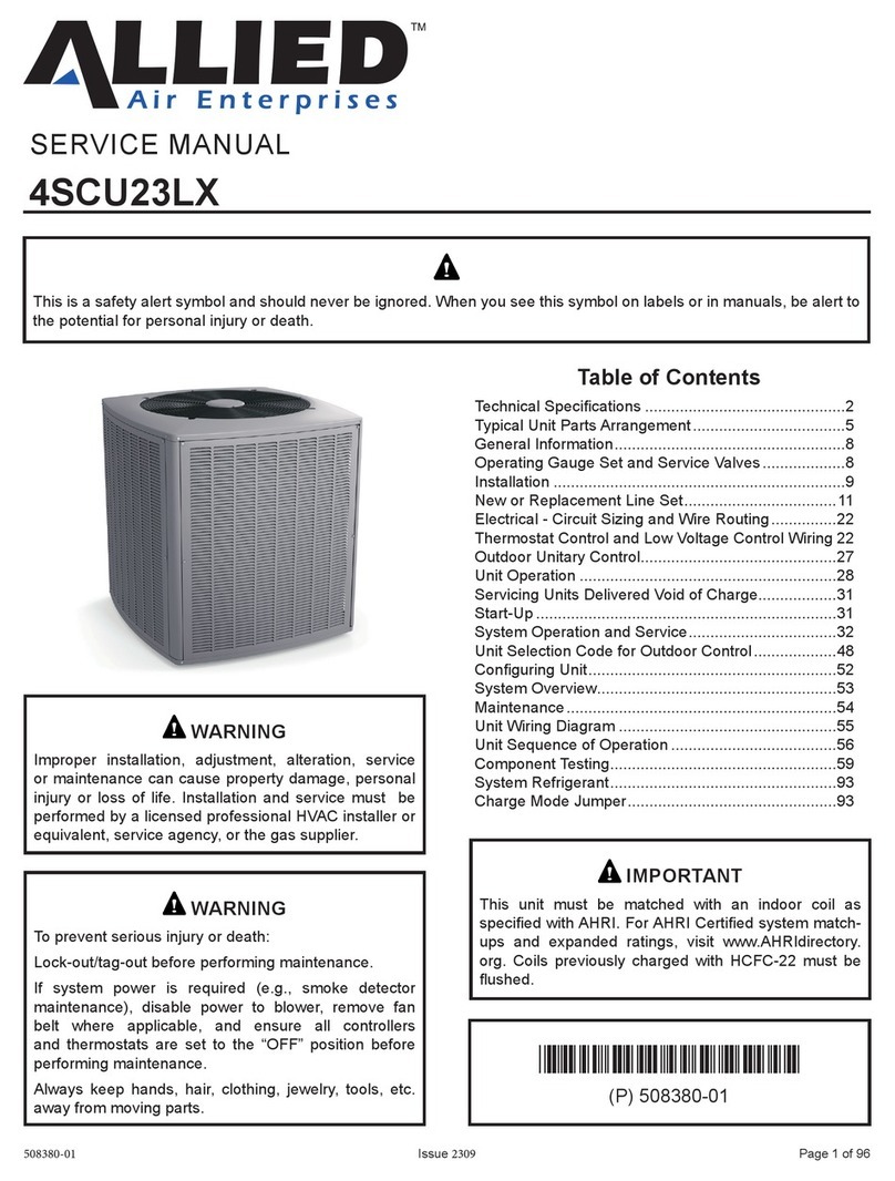
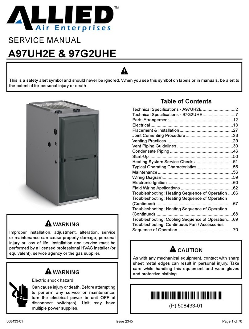
Allied A97DF2E User manual

508434-01 Issue 2350 Page 1 of 69
SERVICE MANUAL
A97DF2E & 97G2DFE
(P) 508434-01
*P508434-01*
Table of Contents
Technical Specications - A97DF2E............................2
Technical Specications - 97G2DFE ...........................7
Parts Arrangement.....................................................12
Electrical....................................................................13
Placement & Installation............................................27
Joint Cementing Procedure.......................................28
Venting Practices.......................................................29
Vent Piping Guidelines ..............................................30
Condensate Piping ....................................................45
Start-Up .....................................................................49
Heating System Service Checks ...............................50
Typical Operating Characteristics..............................54
Maintenance..............................................................55
Wiring Diagram..........................................................58
Electronic Ignition ......................................................59
Field Wiring Applications ...........................................61
Troubleshooting: Heating Sequence of Operation ....65
Troubleshooting: Heating Sequence of Operation
(Continued)................................................................66
Troubleshooting: Heating Sequence of Operation
(Continued)................................................................67
Troubleshooting: Cooling Sequence of Operation.....68
Troubleshooting: Continuous Fan / Accessories
Sequence of Operation..............................................69
This is a safety alert symbol and should never be ignored. When you see this symbol on labels or in manuals, be alert to
the potential for personal injury or death.
Electric shock hazard.
Can cause injury or death. Before attempting
to perform any service or maintenance,
turn the electrical power to unit OFF at
disconnect switch(es). Unit may have
multiple power supplies.
WARNING
As with any mechanical equipment, contact with sharp
sheet metal edges can result in personal injury. Take
care while handling this equipment and wear gloves
and protective clothing.
CAUTION
Improper installation, adjustment, alteration, service
or maintenance can cause property damage, personal
injury or loss of life. Installation and service must be
performed by a licensed professional HVAC installer (or
equivalent), service agency or the gas supplier.
WARNING

508434-01Issue 2350Page 2 of 69
Technical Specications - A97DF2E
MODEL NUMBER GUIDE
PHYSICAL AND ELECTRICAL DATA
Model
1st Stage 2nd Stage
AFUE
(ICUS)
Nom. Cooling
Capacity
(tons)
Gas Inlet
(in.)
Volts / Hz /
Phase
Min. Time
Delay Breaker
or Fuse
Nominal F.L.A.
Trans.
(V.A.)
Approx. Weight
(lbs.)
Input
(Btuh)
Output
(Btuh)
Input
(Btuh)
Output
(Btuh)
Downow
A97DF2E045B12S 29,000 28,000 44,000 43,000 97.0 31/2 120-60-1 15 --- 40 124
A97DF2E070B16S 43,000 42,000 66,000 65,000 97.0 41/2 120-60-1 15 --- 40 138
A97DF2E090C16S 57,000 56,000 88,000 86,000 97.0 51/2 120-60-1 20 10.9 40 153
A97DF2E110C20S 72,000 70,000 110,000 108,000 97.0 51/2 120-60-1 20 10.9 40 164
Note: For vent length and clearances to combustibles, please reference installation instructions.
Major Revision Code
Numeric Code
Heat Exch
S = Stainless Steel Heat
Exchanger
Nom. CFM x 100
08 = 2 Ton add on cooling
12 = 3 Ton add on cooling
16 = 4 Ton add on cooling
20 = 5 Ton add on cooling
Cabinet Width
B = 17.5” width
C = 21.0” width
D = 24.5” width
A
Flagship
AFUE
97 = 97% Efficency
Configuration
UH = Upflow/Horizontal
DF = Downflow
Stages
2 = Two Stage
Blower Drive
E = High Efficiency Motor
BTUH
Heating Input x 1000
A 97 DF 2 E 110 C 20 S -01
FILTER REQUIREMENT DATA
Airow Descriptor
Disposable Filters Cleanable Filters
Minimum Area
(sq. in.)
Minimum Area
(sq.in.)
12 576 288
16 768 384
20 960 480
1. The Airflow Descriptor is the two digits following the “B”, “C”, or “D” in the model number; e.g. “20” is the Airflow Descriptor.
2. Areas shown for permanent filters are based on filters rated at 600 feet per minute face velocity.

508434-01 Issue 2350 Page 3 of 69
BLOWER DATA: DOWNFLOW
A97DF2E045B12S PERFORMANCE (Less Filter)
External
Static
Pressure
in. w.c.
Rise Range °F Air Volume / Watts at Various Blower Speeds
1st
Stage
2nd
Stage
High Medium-High Medium Medium-Low Low
cfm Watts cfm Watts cfm Watts cfm Watts cfm Watts
0.10
15-45 30-60
1434 383 1275 277 1169 217 921 126 860 106
0.20 1401 395 1237 288 1140 227 879 134 817 115
0.30 1363 398 1211 297 1101 238 833 140 773 122
0.40 1300 383 1179 308 1070 243 798 151 733 131
0.50 1228 367 1151 316 1036 256 755 156 692 136
0.60 1146 343 1105 319 1005 263 710 163 645 144
0.70 1058 318 1038 309 971 272 672 170 598 154
0.80 930 286 942 284 909 272 614 179 557 158
0.90 807 251 811 251 799 251 569 184 518 163
1.00 645 222 669 224 630 216 532 189 473 169
A97DF2E070B16S PERFORMANCE (Less Filter)
External
Static
Pressure
in. w.c.
Rise Range °F Air Volume / Watts at Various Blower Speeds
1st
Stage
2nd
Stage
High Medium-High Medium Medium-Low Low
cfm Watts cfm Watts cfm Watts cfm Watts cfm Watts
0.10
20-50 30-60
1709 485 1510 339 1336 240 1226 196 991 114
0.20 1675 501 1474 350 1294 249 1180 204 927 122
0.30 1638 513 1437 362 1244 261 1127 215 863 130
0.40 1601 529 1386 376 1187 270 1082 226 797 139
0.50 1563 541 1353 388 1139 282 1033 232 727 147
0.60 1511 539 1310 401 1100 293 979 245 661 155
0.70 1445 525 1272 410 1048 304 940 255 604 159
0.80 1339 499 1234 421 1013 313 862 264 531 174
0.90 1243 470 1161 424 952 326 811 272 481 182
1.00 1119 439 1092 414 907 330 763 281 435 192
A97DF2E090C16S PERFORMANCE (Less Filter)
External
Static
Pressure
in. w.c.
Rise Range °F Air Volume / Watts at Various Blower Speeds
1st
Stage
2nd
Stage
High Medium-High Medium Medium-Low Low
cfm Watts cfm Watts cfm Watts cfm Watts cfm Watts
0.10
25-55 35-65
1750 446 1520 308 1389 240 1306 206 1179 158
0.20 1708 463 1487 323 1359 254 1265 217 1130 171
0.30 1685 477 1456 339 1326 264 1228 230 1090 182
0.40 1630 478 1421 350 1274 281 1192 239 1046 192
0.50 1558 462 1394 363 1246 291 1157 251 989 202
0.60 1458 432 1354 373 1209 300 1114 264 952 210
0.70 1371 408 1312 381 1177 314 1079 271 913 220
0.80 1231 368 1234 366 1138 324 1038 282 861 230
0.90 1118 343 1093 336 1093 327 997 291 843 237
1.00 1008 315 976 309 987 306 952 292 794 242

508434-01Issue 2350Page 4 of 69
BLOWER DATA: DOWNFLOW
A97DF2E110C20S PERFORMANCE (Less Filter)
External
Static
Pressure
in. w.c.
Rise Range °F Air Volume / Watts at Various Blower Speeds
1st
Stage
2nd
Stage
High Medium-High Medium Medium-Low Low
cfm Watts cfm Watts cfm Watts cfm Watts cfm Watts
0.10
30-60 40-70
2174 694 1920 474 1754 365 1631 312 1441 225
0.20 2136 706 1877 488 1709 379 1583 322 1387 237
0.30 2095 718 1832 500 1658 391 1530 332 1323 247
0.40 2058 734 1792 512 1617 403 1487 345 1276 256
0.50 2006 742 1745 525 1570 413 1433 354 1223 265
0.60 1940 727 1704 538 1523 426 1379 368 1168 276
0.70 1863 702 1665 550 1479 436 1340 377 1110 290
0.80 1765 669 1622 563 1439 445 1288 388 1061 293
0.90 1673 642 1582 572 1398 454 1254 397 1013 304
1.00 1559 599 1522 568 1354 466 1214 407 949 311

508434-01 Issue 2350 Page 5 of 69
ACCESSORY LIST
Description Catalog Number
Return Air Base
Return Air Base 17.5 Inch 68W62
Return Air Base 21.0 Inch 68W63
Return Air Base 24.5 Inch 68W64
Downow Combustible Flooring Base
17.5" B Width 11M60
21.0" C Width 11M61
External Filter Rack kits
1 pack (16 x 25) 1.841018
10 pack (16 x 25) 1.841039
Downow Specic Air Filters
17.5" 51W07
21.0" 51W08
24.5" 51W09
Horizontal Suspension Kit
80% & 90% Kit 51W10
Concentric Vent Kit (90% Furnaces only) US Only
1-1/2" Vent Version 71M80
2" Vent Version 69M29
3" Vent Version 60L46
Concentric Vent Kit (90% Furnaces only) Canada Only
1-1/2" and 2" Vent Version 44W92
3" Vent Version 44W93
Flush Mount Termination (90% Furnaces only)
2" & 3.0" Vent - US Version 51W11
2" & 3.0" Vent - ULC S636 Compliant (Canada) 51W12
High Altitude Orice Kits (7500'+)
2-Stage 97% UH/DF - Natural Gas 51W01
2-Stage 97% UH/DF - Propane Gas 78W97
For vent length and clearances to combustibles, please reference installation instructions.

508434-01Issue 2350Page 6 of 69
ACCESSORY LIST
Description Catalog Number
High Altitude Pressure Swiches
2-Stage 97% UH/DF (4,501 - 7,500 ft) [045] 14A51
2-Stage 97% UH/DF (4,501 - 7,500 ft) [070] 14A48
2-Stage 97% UH/DF (4,501 - 7,500 ft) [090] 14A54
2-Stage 97% UH/DF (4,501 - 7,500 ft) [110] 25B93
2-Stage 97% UH/DF (7,501 - 10,000 ft) [045] 14A53
2-Stage 97% UH/DF (7,501 - 10,000 ft) [070] 14A54
2-Stage 97% UH/DF (7,501 - 10,000 ft) [090] 14A53
2-Stage 97% UH/DF (7,501 - 10,000 ft) [110] 14A45
Natural to LP Kits
2-Stage 90 11K48
2-Stage 90 High Altitude (>7500') 11K47
Low Input (30K Btuh) 17H64
LP to Natural Kits
2-Stage - 90 (45K-110K Btuh) 77W10
Night Service Kits
Two Stage 10U95
Safety Night Service Kit 68W83
Twinning Kit
16W72 Constant Torque Gas Furnace Twinning Kit
For vent length and clearances to combustibles, please reference installation instructions.

508434-01 Issue 2350 Page 7 of 69
Technical Specications - 97G2DFE
MODEL NUMBER GUIDE
PHYSICAL AND ELECTRICAL DATA
Model
1st Stage 2nd Stage
AFUE
(ICUS)
Nom. Cooling
Capacity
(tons)
Gas Inlet
(in.)
Volts / Hz /
Phase
Min. Time
Delay Breaker
or Fuse
Nominal F.L.A.
Trans.
(V.A.)
Approx. Weight
(lbs.)
Input
(Btuh)
Output
(Btuh)
Input
(Btuh)
Output
(Btuh)
Downow
97G2DF045BE12 29,000 28,000 44,000 43,000 97.0 31/2 120-60-1 15 --- 40 123
97G2DF070BE16 43,000 42,000 66,000 65,000 97.0 41/2 120-60-1 15 --- 40 137
97G2DF090CE16 57,000 56,000 88,000 86,000 97.0 51/2 120-60-1 20 10.9 40 147
97G2DF110CE20 72,000 70,000 110,000 108,000 97.0 51/2 120-60-1 20 10.9 40 166
Note: For vent length and clearances to combustibles, please reference installation instructions.
FILTER REQUIREMENT DATA
Airow Descriptor
Disposable Filters Cleanable Filters
Minimum Area
(sq. in.)
Minimum Area
(sq.in.)
12 576 288
16 768 384
20 960 480
1. The Airflow Descriptor is the two digits following the “B”, “C”, or “D” in the model number; e.g. “20” is the Airflow Descriptor.
2. Areas shown for permanent filters are based on filters rated at 600 feet per minute face velocity.
MAJOR REVISION
NUMERIC CODE
CFM
12 = 3 TON ADD ON COOLING
16 = 4 TON ADD ON COOLING
20 = 5 TON ADD ON COOLING
BLOWER DRIVE
P = PSC
E = HIGH EFFICIENCY
V= VARIABLE SPEED
CABINET WIDTH
B = 17.5” WIDTH
C = 21.0” WIDTH
D = 24.5” WIDTH
AFUE
97% EFFICIENCY
GAS
GAS
STAGES
2 = TWO STAGE
CONFIGURATION
UH = UPFLOW/HORIZONTAL
DF = DOWN FLOW
BTUH INPUT
HEATING INPUT X 1000
9 7 G 2 UH 070 B E 12 - 01

508434-01Issue 2350Page 8 of 69
BLOWER DATA: DOWNFLOW
97G2DF045BE12 PERFORMANCE (Less Filter)
External
Static
Pressure
in. w.c.
Rise Range °F Air Volume / Watts at Various Blower Speeds
1st
Stage
2nd
Stage
High Medium-High Medium Medium-Low Low
cfm Watts cfm Watts cfm Watts cfm Watts cfm Watts
0.10
15-45 30-60
1434 383 1275 277 1169 217 921 126 860 106
0.20 1401 395 1237 288 1140 227 879 134 817 115
0.30 1363 398 1211 297 1101 238 833 140 773 122
0.40 1300 383 1179 308 1070 243 798 151 733 131
0.50 1228 367 1151 316 1036 256 755 156 692 136
0.60 1146 343 1105 319 1005 263 710 163 645 144
0.70 1058 318 1038 309 971 272 672 170 598 154
0.80 930 286 942 284 909 272 614 179 557 158
0.90 807 251 811 251 799 251 569 184 518 163
1.00 645 222 669 224 630 216 532 189 473 169
97G2DF070BE16 PERFORMANCE (Less Filter)
External
Static
Pressure
in. w.c.
Rise Range °F Air Volume / Watts at Various Blower Speeds
1st
Stage
2nd
Stage
High Medium-High Medium Medium-Low Low
cfm Watts cfm Watts cfm Watts cfm Watts cfm Watts
0.10
20-50 30-60
1709 485 1510 339 1336 240 1226 196 991 114
0.20 1675 501 1474 350 1294 249 1180 204 927 122
0.30 1638 513 1437 362 1244 261 1127 215 863 130
0.40 1601 529 1386 376 1187 270 1082 226 797 139
0.50 1563 541 1353 388 1139 282 1033 232 727 147
0.60 1511 539 1310 401 1100 293 979 245 661 155
0.70 1445 525 1272 410 1048 304 940 255 604 159
0.80 1339 499 1234 421 1013 313 862 264 531 174
0.90 1243 470 1161 424 952 326 811 272 481 182
1.00 1119 439 1092 414 907 330 763 281 435 192
97G2DF090CE16 PERFORMANCE (Less Filter)
External
Static
Pressure
in. w.c.
Rise Range °F Air Volume / Watts at Various Blower Speeds
1st
Stage
2nd
Stage
High Medium-High Medium Medium-Low Low
cfm Watts cfm Watts cfm Watts cfm Watts cfm Watts
0.10
25-55 35-65
1750 446 1520 308 1389 240 1306 206 1179 158
0.20 1708 463 1487 323 1359 254 1265 217 1130 171
0.30 1685 477 1456 339 1326 264 1228 230 1090 182
0.40 1630 478 1421 350 1274 281 1192 239 1046 192
0.50 1558 462 1394 363 1246 291 1157 251 989 202
0.60 1458 432 1354 373 1209 300 1114 264 952 210
0.70 1371 408 1312 381 1177 314 1079 271 913 220
0.80 1231 368 1234 366 1138 324 1038 282 861 230
0.90 1118 343 1093 336 1093 327 997 291 843 237
1.00 1008 315 976 309 987 306 952 292 794 242

508434-01 Issue 2350 Page 9 of 69
BLOWER DATA: DOWNFLOW
97G2DF110CE20 PERFORMANCE (Less Filter)
External
Static
Pressure
in. w.c.
Rise Range °F Air Volume / Watts at Various Blower Speeds
1st
Stage
2nd
Stage
High Medium-High Medium Medium-Low Low
cfm Watts cfm Watts cfm Watts cfm Watts cfm Watts
0.10
30-60 40-70
2174 694 1920 474 1754 365 1631 312 1441 225
0.20 2136 706 1877 488 1709 379 1583 322 1387 237
0.30 2095 718 1832 500 1658 391 1530 332 1323 247
0.40 2058 734 1792 512 1617 403 1487 345 1276 256
0.50 2006 742 1745 525 1570 413 1433 354 1223 265
0.60 1940 727 1704 538 1523 426 1379 368 1168 276
0.70 1863 702 1665 550 1479 436 1340 377 1110 290
0.80 1765 669 1622 563 1439 445 1288 388 1061 293
0.90 1673 642 1582 572 1398 454 1254 397 1013 304
1.00 1559 599 1522 568 1354 466 1214 407 949 311

508434-01Issue 2350Page 10 of 69
ACCESSORY LIST
Description Catalog Number
Return Air Base
Return Air Base 17.5 Inch 68W62
Return Air Base 21.0 Inch 68W63
Return Air Base 24.5 Inch 68W64
Downow Combustible Flooring Base
17.5" B Width 11M60
21.0" C Width 11M61
External Filter Rack kits
1 pack (16 x 25) 1.841018
10 pack (16 x 25) 1.841039
Downow Specic Air Filters
17.5" 51W07
21.0" 51W08
24.5" 51W09
Horizontal Suspension Kit
80% & 90% Kit 51W10
Concentric Vent Kit (90% Furnaces only) US Only
1-1/2" Vent Version 71M80
2" Vent Version 69M29
3" Vent Version 60L46
Concentric Vent Kit (90% Furnaces only) Canada Only
1-1/2" and 2" Vent Version 44W92
3" Vent Version 44W93
Flush Mount Termination (90% Furnaces only)
2" & 3.0" Vent - US Version 51W11
2" & 3.0" Vent - ULC S636 Compliant (Canada) 51W12
High Altitude Orice Kits (7500'+)
2-Stage 97% UH/DF - Natural Gas 51W01
2-Stage 97% UH [030] - Natural Gas 14C92
2-Stage 97% UH/DF - Propane Gas 78W97
2-Stage 97% UH [030] - Propane Gas 14C93
For vent length and clearances to combustibles, please reference installation instructions.

508434-01 Issue 2350 Page 11 of 69
ACCESSORY LIST
Description Catalog Number
High Altitude Pressure Swiches
2-Stage 97% UH (4,501 - 7,500 ft) [030] 14A47
2-Stage 97% UH/DF (4,501 - 7,500 ft) [045] 14A51
2-Stage 97% UH/DF (4,501 - 7,500 ft) [070] 14A48
2-Stage 97% UH/DF (4,501 - 7,500 ft) [090] 14A54
2-Stage 97% UH/DF (4,501 - 7,500 ft) [110] 25B93
2-Stage 97% UH (7,501 - 10,000 ft) [030] 14A50
2-Stage 97% UH/DF (7,501 - 10,000 ft) [045] 14A53
2-Stage 97% UH/DF (7,501 - 10,000 ft) [070] 14A54
2-Stage 97% UH/DF (7,501 - 10,000 ft) [090] 14A53
2-Stage 97% UH/DF (7,501 - 10,000 ft) [110] 14A45
Natural to LP Kits
2-Stage 90 11K48
2-Stage 90 High Altitude (>7500') 11K47
Low Input (30K Btuh) 17H64
LP to Natural Kits
2-Stage - 90 (45K-110K Btuh) 77W10
Night Service Kits
Two Stage 10U95
Safety Night Service Kit 68W83
Twinning Kit
16W72 Constant Torque Gas Furnace Twinning Kit
For vent length and clearances to combustibles, please reference installation instructions.

508434-01Issue 2350Page 12 of 69
Parts Arrangement
CONTROL BOX
(Includes integrated control,
transformer and door switch)
BAG ASSEMBLY
(shipping location)
CONSTANT
TORQUE BLOWER
MOTOR
(hidden)
OUTER
ACCESS
PANEL
COMBUSTION
AIR INDUCER
BURNER BOX ASSEMBLY
(includes sensor, rollout switches and ignitor) GAS VALVE
BLOWER DECK
COLD END HEADER BOX
PRIMARY LIMIT
HEAT EXCHANGER
ASSEMBLY
COMBUSTION AIR INDUCER
PRESSURE SWITCH
Figure 1.

508434-01 Issue 2350 Page 13 of 69
Electrical
ELECTROSTATIC DISCHARGE (ESD)
Precautions and Procedures
Electrostatic discharge can aect electronic
components. Take precautions to
neutralize electrostatic charge by touching
your hand and tools to metal prior to
handling the control.
CAUTION
A97DF2E / 97G2DFE unit components are shown in Figure
1. The gas valve, combustion air inducer and burners can
be accessed by removing the access panel. Electrical
components are in the control box (Figure 2) found in the
blower section.
Control Box Components (Figure 2)
Transformer
Integrated Control
Interlock Switch
Circuit Breaker
Figure 2. Control Box
Transformer (T1)
A transformer located in the control box provides power
to the low voltage section of the unit. Transformers on all
models are rated 40VA with a 120V primary and a 24V
secondary.
Door Interlock Switch (S51)
A door interlock switch is wired in series with line voltage.
When the inner blower access panel is removed the unit
will shut down.
Circuit Breaker (CB8)
A 24V circuit breaker is also located in the control box. The
switch provides overcurrent protection to the transformer
(T1). The breaker is rated at 3A at 32V. If the current
exceeds this limit the breaker will trip and all unit operation
will shutdown. The breaker can be manually reset by
pressing the button on the face. See Figure 3.
Figure 3. Circuit Breaker (CB8)
PRESS TO RESET
Integrated Ignition Control (A92)
Shock hazard.
Disconnect power before servicing.
Control is not eld repairable. If control is
inoperable, simply replace entire control.
Can cause injury or death. Unsafe
operation will result if repair is attempted.
WARNING
Units are equipped with a two-stage, integrated control.
The system consists of a ignition / blower control (Figure
4 and Figure 5) with control pin designations in Table 1
and Table 2 and ignitor (Figure 12). The control and ignitor
work in combination to ensure furnace ignition and ignitor
durability. The control provides gas ignition, safety checks
and indoor blower control with two-stage gas heating.
The furnace combustion air inducer, gas valve and indoor
blower are controlled in response to various system inputs
such as thermostat signal, pressure and limit switch signal
and ame signal. The control features a seven-segment
LED display, indicating furnace status and error codes.
The LED ashes in single digits. For example, using Table
4 under LIMIT CODE, an “E” followed by “2” followed by “5”
followed by “0”, the limit switch circuit is open. The control
also has two unpowered (dry) 1/4” contacts for a humidier
and a 120 volt accessory terminal. Both rated at (1) one
amp each.
Pin # Function
1Ignitor
2 Combustion Air Inducer High Speed
3Combustion Air Inducer Low Speed
4Combustion Air Inducer Neutral
5Ignitor Neutral
Table 1. 5-Pin Terminal Designations

508434-01Issue 2350Page 14 of 69
Pin # Function
1Gas Valve Second Stage
2 Second Stage Pressure Switch
3Rollout Switch In
4Ground
524V Hot
6Primary Limit In
7 Gas Valve First Stage
8Gas Valve Common
924V Neutral
10 Ground
11 Primary Limit Out
12 First Stage Pressure Switch
Table 2. 12-Pin Terminal Designations
Electric Shock Hazard.
Can cause injury or death. Unit must be
properly grounded in accordance with
national and local codes.
WARNING
Fire Hazard.
Use of aluminum wire with this product may result in a
re, causing property damage, severe injury or death.
Use copper wire only with this product.
WARNING
Electronic Ignition
At the beginning of the heat cycle the integrated control
monitors the rst stage and second stage combustion air
inducer pressure switch. The control will not begin the
heating cycle if the rst stage pressure switch is closed
(bypassed). Likewise the integrated control will not begin
the second stage heating cycle if the second stage
pressure switch is closed, and will remain in rst stage
heat. However, if the second stage pressure switch closes
during the rst stage heat pre-purge, the control will allow
second stage heat. Once the rst stage pressure switch
is determined to be open, the combustion air inducer is
energized on low (rst stage) heat speed. When the
dierential in the pressure switch is great enough, the
pressure switch closes and a 15-second pre-purge begins.
After the 15-second pre-purge period, the ignitor warms
up for 20 seconds after which the gas valve opens for a
4-second trial for ignition. The ignitor remains energized
during the trial until ame is sensed. If ignition is not proved
during the 4-second period, the control will try four more
times with an inter purge and warm-up time between trials
of 35 seconds. After a total of ve trials for ignition (including
the initial trial), the control goes into Watchguard-Flame
Failure mode. After a 60-minute reset period, the control
will begin the ignition sequence again.
NOTE: During abnormal conditions such as low supply
voltage or low outdoor temperatures and the low re
pressure switch does not close, the combustion air inducer
will switch to high speed. After the low & high pressure
switch close, the unit will proceed with a 15 sec pre-purge,
followed by a 20 sec ignitor warm up, then ignition on
highre. After 10 to 20 seconds of high re operation the
unit will switch to low re.
Two Stage Operation / Thermostat Selection DIP
Switch
The control can be utilized in two modes: SINGLE-STAGE
thermostat or TWO-STAGE thermostat. The thermostat
selection is made using a DIP switch and must be positioned
for the particular application. DIP switch 1, labeled T”STAT
HEAT STAGE is factory-set in the OFF position for use
with a two-stage thermostat. Move the DIP switch to ON
for use with a single stage thermostat.
While in the single-stage thermostat mode, the burners will
always re on rst-stage heat. The combustion air inducer
will operate on low speed and indoor blower will operate on
low heat speed. The unit will switch to second stage heat
after a “recognition period”. DIP switch 2, labeled SECOND
STAGE DELAY, is factory set in the OFF position for a 7
minute recognition period. The switch can be moved to the
ON position for a 12 minute recognition period, after which
time the unit will switch to second-stage heat.
While in the two-stage thermostat mode, the burners will
re on rst-stage heat. The combustion air inducer will
operate on low speed and indoor blower will operate on low
heat speed. The unit will switch to second-stage heat on
call from the indoor thermostat. If there is a simultaneous
call for rst and second stage heat, the unit will re on
rst stage heat and switch to second stage heat after 30
seconds of operation. See Sequence of Operation ow
charts in the back of this manual for more detail.

508434-01 Issue 2350 Page 15 of 69
Figure 4. Integrated Control
Flame Sense
S4 DIP Switches
24VAC Indoor
Blower Terminals
HUM ACC
Ignitor and Combustion
Air Inducer
Neutrals
On Board Links
LED
Diagnostic Push
Button
3/16” QUICK CONNECT TERMINALS
FLAME SENSE SIGNAL
HI COOL 24VAC
LO COOL 24VAC
LO HEAT 24VAC
PARK
PARK
COMMON 24VAC
1/4” QUICK CONNECT TERMINALS
NEUTRALS = 120 VAC NEUTRAL
HUM = UNPOWERED NORMALLY OPEN (DRY) CONTACTS
LI = 120VAC INPUT TO CONTROL
A
CC = 120VAC OUTPUT TO OPTIONAL ACCESSORY
THERMOSTAT CONNECTIONS (TB1)
DS = DEHUMIDIFICATION SIGNAL
W2 = HEAT DEMAND FROM 2ND STAGE TSTAT
W1 = HEAT DEMAND FROM 1ST STAGE TSTAT
R = CLASS 2 VOLTAGE TO TSTAT
G = MANUAL FAN FROM TSTAT
C = TSTAT SIGNAL GROUND CONNECTED TO
TRANSFORMER GRD (TR) & CHASSIS GROUND (GRD)
Y1 = TSTAT 1ST STAGE COOL SIGNAL
Y2 = TSTAT 2ND STAGE COOL SIGNAL
O = TSTAT SIGNAL TO HEAT PUMP REVERSING VALVE
DH = NOT USED
L = NOT USED

508434-01Issue 2350Page 16 of 69
Figure 5. Integrated Control Conguration Guide
HEATING BLOWER−OFF DELAY
60 SECOND
HTG BLOWER
OFF DELAY
120 SECOND
HTG BLOWER
OFF DELAY
180 SECOND
HTG BLOWER
OFF DELAY
FLAME
15
HSI/CAI
2ND STAGE HEAT ON DELAY
7 MIN
UPSTAGE
DELAY
12 MIN
UPSTAGE
DELAY
*
W915
2 STAGE
COMPR
1−STG COMPRESSOR
2−STAGE
COMPRESSOR LINK
(JUMPERS Y1 to Y2)
W915
DO NOT CUT
2−STG COMPRESSOR
HEAT PUMP LINK
(JUMPERS R to O)
W951
(JUMPERS R to DS)
W914
W915
2 STAGE
COMPR
CUT LINK
A/C UNIT
DO NOT CUT
HEAT PUMP UNIT
CUT LINK
W951
HEAT
PUMP
W951
HEAT
PUMP
W914
DEHUM
NO SIGNATURESTAT
W/ DS CONNECTION
DO NOT CUT
SIGNATURESTAT W/
DS CONNECTION
CUT LINK
W914
DEHUM
1
1
1
ON−BOARD LINK
OPTION SELECTION
1234567
1234567
123567
4
123567
4
NEUTRALS
L1
ACC
HUM
14
36
P79
110
312
J2
4 7
W915
2 STAGE
COMPR
W951
HEAT
PUMP
W914
DEHUM
CUT FOR
OPTION
SELECTION
123456
ON
SureLight
W1W2 GY2 Y1 CC DH LODSR
W1
W2
G
Y2
Y1
C
C
R
L
DH
7
1
ON
ON
ON
ON
90 SECOND
HTG BLOWER
OFF DELAY
*1234567
ON
1234567
ON
THERMOSTAT SELECTION
1−STAGE
THERMOSTAT
(TIMED STAGING)
−SEE SW #2
TWO STAGE
THERMOSTAT
*
1234567
1234567
ON
ON
−BLOWER ON DELAY − 30 SEC. FIXED
1234567
ON
SENSE
IGN
CAI2
CAI1
N
N
J3
S1
S4S3
DIAGNOSTIC
LED
DIAGNOSTIC
PUSH BUTTON
*45 SECOND
COOL BLOWER
OFF DELAY
2 SECOND
COOL BLOWER
OFF DELAY
123567
4
123567
4
ON
ON
COOLING BLOWER-OFF DELAY
1234567
ON
1234567
ON
1234567
ON
CONTINUOUS FAN SETTINGS
LOW HEAT SPEED
LOW COOL SPEED
HIGH HEAT SPEED
HIGH COOL SPEED
DEHUMIFICATION LINK
- CUT ON-BOARD LINK (SOLDER TRACE)
COMPLETELY THROUGH BOTH LAYERS ON THE
CONTROL BOARD
- LINKS CUT IN ERROR - INSTALL A JUMPER ON THE
APPROPRIATE TERMINALS ON THE TERMINAL
STRIP
- PROTECTIVE PLASTIC FILM ON DIP SWITCHES
MAY BE REMOVED FOR EASE IN SETTING OF DIP
SW.
* FACTORY DEFAULT

508434-01 Issue 2350 Page 17 of 69
Display Action (when button released)
No change (idle)* Remain in idle mode
Solid “E” Enter diagnostic recal mode
Solid “F” Enter ame signal mode
* No change implies the display will continue to show whatever is currently being displayed for normal operation (blinking decimal,
active error code, heat state, etc.)
Table 3. Integrated Control Diagnostic Modes
Code Diagnostic Codes/Status of Equipment Action Required to Clear and Recover
.Idle mode (Decimal blinks at 1 Hertz -- 0.5
second ON, 0.5 second OFF).
CCooling stage (1 second ON, 0.5 second OFF)
1 or 2 displayed / Pause / Repeat codes.
d Dehumidication mode (1 second ON, 1
second OFF) / Pause / Repeat Codes).
HGas Heat Stage (1 second ON, 0.5 second
OFF) 1 or 2 displayed / Pause / Repeat codes.
Blinking during ignition.
hHeat pump stage.
E110 Low line voltage. Line Voltage Low (Voltage lower than nameplate rating). Check power line
voltage and correct. Alarm clears 5 seconds after fault recovered.
E111 Line voltage polarity reversed. Reverse line power voltage wiring. System resumes normal operation 5
seconds after fault recovered.
E112 Ground not detected. System shuts down. Provide proper earth ground. System resumes normal
operation 5 seconds after fault recovered.
E113 High line voltage. Line Voltage High (Voltage higher than nameplate rating). Provide power
voltage within proper range. System resumes normal operation 5 seconds
after fault recovered.
E114 Line voltage frequency out-of-range. No 60 Hertz Power. Check voltage and line power frequency. Correct
voltage and frequency problems. System resumes normal operation 5
seconds after fault recovered.
E115 Low 24V - Control will restart if the error
recovers.
24-Volt Power Low (Range is 18 to 30 volts). Check and correct voltage.
Check for additional power-robbing equipment connected to system. May
require installation of larger VA transformer to be installed in furnace / air
handler. Clears after fault recovered.
E117 Poor ground detected (Warning only) Provide proper grounding for unit. Check for proper earth ground to the
system. Warning only will clear 30 seconds after fault recovered.
E125 Control failed self-check, internal error,
failed hardware. Will restart if error recovers.
Integrated control not communicating. Covers
hardware errors (ame sense circuit faults, pin
shorts, etc.).
Hardware problem on the control. Cycle power on control. Replace if
problem prevents service and is persistent. Critical alert. Cleared 300
seconds after fault recovered.
E200 Hard lockout - Rollout circuit open or previously
open.
Correct cause of rollout trip, or replace ame rollout switch. Test furnace
operation. Cleared after fault recovered.
E204 Gas valve mis-wired. Check gas valve operation and wiring. Clears when repaired.
E205 Gas valve control relay contact shorted. Check wiring on control and gas valve. If wiring is correct, replace control.
E206 Gas valve second-stage relay failure. Furnace will operate on 1st stage for remainder of the heating demand.
Will clear after fault recovered. If unable to operate 2nd stage, replace
control.
E207 Hot surface ignitor sensed open. Measure resistance of hot surface ignitor. Replace if open or not within
specied range found in IOM. Resumes normal operation after fault is
cleared.
Table 4. Integrated Diagnostic Codes / Status of Equipment

508434-01Issue 2350Page 18 of 69
Code Diagnostic Codes/Status of Equipment Action Required to Clear and Recover
E223 Low pressure switch failed open. Check pressure (inches w.c.) of low pressure switch closing on heat call.
Measure operating pressure (inches w.c.). Inspect vent and combustion
air inducer for correct operation and restriction. Resumes normal operation
after fault is cleared
E224 Low pressure switch failed closed. Check operation of low pressure switch to see if it is stuck closed on
heat call longer than 150 seconds. Measure operating pressure (inches
w.c.). Inspect vent and combustion air inducer for correct operation and
restriction. Resumes normal operation after fault is cleared.
E225 High pressure switch failed open. Check pressure (inches w.c.) of high pressure switch closing on heat call.
Measure operating pressure (inches w.c.). Inspect vent and combustion air
inducer for correct operation and restriction. Resumes normal operation
after fault is cleared.
E226 High pressure switch failed closed. Check operation of high pressure switch closing on heat call. Measure
operating pressure (inches w.c.). Inspect vent and combustion air inducer
for correct operation and restriction. Resumes normal operation after fault
is cleared.
E227 Low pressure switch open during trial for
ignition or run mode.
Check pressure (inches w.c.) of low pressure switch closing on heat call.
Measure operating pressure (inches w.c.). Inspect vent and combustion
air inducer for correct operation and restriction. Resumes normal operation
after fault is cleared.
E229 Ignition on High Fire - Information Only. Code is displayed if 1) low pressure switch fails to close, then furnace will
switch to high speed inducer to close both low and high pressure switches,
then furnace lights on high re, or 2) if continuous fan is active, furnace
lights on high re for 60 seconds to improve heat exchanger warm up time.
E240 Low ame current - Run mode. Check micro-amperes of ame sensor using control diagnostics or eld-
installed mode. Clean or replace sensor. Measure voltage of neutral to
ground to ensure good unit ground. Alert clears after current heat call has
been completed.
E241 Flame sensed out of sequence - Flame still
present.
Shut o gas. Check for gas valve leak. Replace, if necessary. Alert clears
when fault is recovered.
E250 Limit switch circuit open. Check for proper ring rate on furnace. Ensure there is no blockage in
heater. Check for proper air ow. If limit not closed within 3 minutes, unit will
go into 1-hour soft lockout. Resumes normal operation after fault is cleared.
E270 Soft lockout - Exceeded maximum number of
retries. No ame current sensed.
Check for proper gas ow. Ensure that ignitor is lighting burner. Check
ame sensor current. Clears when heat call nishes successfully.
E271 Soft lockout - Exceeded maximum number of
retries. Last retry failed due to the pressure
switch opening.
Check pressure (inches w.c.) of low pressure switch closing on heat call.
Measure operating pressure (inches w.c.). Inspect vent and combustion air
inducer for correct operation and restriction. Clears when heat call nishes
successfully.
E272 Soft lockout - Exceeded maximum number
of recycles. Last recycle due to the pressure
switch opening.
Check operation of low pressure switch to see if it is stuck closed on
heat call. Check pressure (inches w.c.) of high pressure switch closing
on heat call. Measure operating pressure (inches w.c.). Inspect vent and
combustion air inducer for correct operation and restriction. Clears when
heat call nishes successfully.
E273 Soft lockout - Exceeded maximum number of
recycles. Last recycle due to ame failure.
Check micro-amperes of ame sensor using control diagnostics or eld-
installed mode. Clean or replace sensor. Measure voltage of neutral
to ground to ensure good unit ground. Clears when heat call nishes
successfully.
E274 Soft lockout - Exceeded maximum number of
recycles. Last recycle failed due to the limit
circuit opening or limit remained open longer
than 3 minutes.
Shut down system. 1-hour soft lockout. Check ring rate and air ow.
Check for blockage. Clears when heat call nishes successfully.
E275 Soft lockout - Flame sensed out of sequence.
Flame signal is gone.
Shut o gas. Check for gas valve leak. 1-hour soft lockout. Clears when
ame has been proven stable.
E290 Ignitor circuit fault - Failed ignitor or triggering
circuitry.
Measure resistance of hot surface ignitor. Replace if open or not within
specications. 1-hour soft lockout. Clears when ame has been proven
stable.
Table 4. Integrated Diagnostic Codes / Status of Equipment

508434-01 Issue 2350 Page 19 of 69
Diagnostic LED (Figure 4)
The seven-segment diagnostic LED displays operating
status, error codes and other information. Table 4 lists
diagnostic LED codes.
Diagnostic Push Button (Figure 4)
The diagnostic push button is located adjacent to the seven-
segment diagnostic LED. This button is used to enable
the Error Code Recall “E” mode and the Flame Signal “F”
mode. Press the button and hold it to cycle through a menu
of options. Every ve seconds a new menu item will be
displayed. When the button is released, the displayed item
will be selected. Once all items in the menu have been
displayed, the menu resumes from the beginning until the
button is released.
Error Code Recall Mode
Select ”E” from the menu to access the most recent 10
error codes. Select “c” from the Error Code Recall menu
to clear all error codes. Button must be pressed a second
time while “c” is ashing to conrm command to delete
codes. Press the button until a solid “≡” is displayed to exit
the Error Code Recall mode.
Flame Signal Mode
Select ”F” from the menu to access the ame signal mode.
The integrated control will display the ame current on
seven-segment LED in in micro amps (uA).
Flame signal mode is exited after any of the following:
• Power is reset
• Pressing and holding push button until 3 horizontal
lines “≡” are displayed
• 10 minutes after entering the ame sense mode.
Integrated Control DIP Switches
A97DF2E / 97G2DFE units are equipped with a two-
stage integrated control. This control manages ignition
timing, heating mode fan o delays and indoor blower
speeds based on selections made using the control dip
switches and jumpers. The control includes an internal
watchguard feature which automatically resets the ignition
control when it has been locked out. After one hour of
continuous thermostat demand for heat, the watchguard
will break and remake thermostat demand to the furnace
and automatically reset the control to relight the furnace.
Heating Operation DIP Switch Settings
Switch 1 -- Thermostat Selection -- This unit may be
used with either a single-stage or two-stage thermostat.
The thermostat selection is made using a DIP switch which
must be properly positioned for the particular application.
The DIP switch is factory-positioned for use with a twostage
thermostat. If a single-stage thermostat is to be used, the
DIP switch must be repositioned.
a. Select “OFF” for two-stage heating operation
controlled by a two-stage heating thermostat
(factory setting);
b. Select “ON” for two-stage heating operation
controlled by a single-stage heating thermostat.
This setting provides a timed delay before second-
stage heat is initiated.
Switch 2 --- Second Stage Delay (Used with Single-
Stage Thermostat Only) -- This switch is used to determine
the second stage on delay when a single-stage thermostat
is being used. The switch is factory-set in the OFF position,
which provides a 7-minute delay before second-stage heat
is initiated. If the switch is toggled to the ON position, it
will provide a 12-minute delay before second-stage heat is
initiated. This switch is only activated when the thermostat
selector jumper is positioned for single-stage thermostat
use.
Indoor Blower Operation DIP Switch Settings
Switches 3 and 4 -- Heating Mode Blower-O Delay --
The blower-on delay of 30 seconds is not adjustable. The
blower-o delay (time that the blower operates after the
heating demand has been satised) can be adjusted by
moving switches 3 and 4 on the integrated control. The
unit is shipped from the factory with a blower-o delay
of 90 seconds. The blower o delay aects comfort and
is adjustable to satisfy individual applications. Adjust
the blower o delay to achieve a supply air temperature
between 90° and 110°F at the exact moment that the blower
is de-energized. Longer o delay settings provide lower
supply air temperatures; shorter settings provide higher
supply air temperatures. Table 5 provides the blower o
timings that will result from dierent switch settings.
Blower O Delay
(seconds) Switch 3 Switch 4
60 On O
90 (Factory) O O
120 O On
180 On On
Table 5. Blower O Heating Mode Delay Switch
Settings

508434-01Issue 2350Page 20 of 69
Switch 5 -- Cooling Mode Blower-O Delay -- The unit
is shipped from the factory with the dip switch positioned
OFF for a 45 second delay. Table 6 provides the cooling
mode o delay settings.
Blower O Delay
(seconds) Switch 5
45 (Factory) O
2 On
Table 6. Blower O Cooling Mode Delay Switch
Settings
Switches 6 and 7 -- Continuous Fan Mode -- Continuous
fan speed can be controlled by changing DIP switch
positions. Table 7 provides DIP switch settings for
continuous fan mode.
Continuous Fan
Mode Switch 6 Switch 7
Low Heat Speed
(Factory) O O
Low Cool Speed O On
High Heat Speed On O
High Cool Speed On On
Table 7. Continuous Fan Mode Settings
Onboard Links
W914 Dehum
Onboard link W914, is a clippable connection between
terminals R and DS on the integrated control. W914 must
be cut when the furnace is installed with a thermostat which
features humidity control. If the link is not cut, terminal “DS”
will remain energized not allowing the blower to reduce to
low cool speed upon a call for dehumidication.
W951 Heat Pump (R to O)
Onboard link W951 is a clippable connection between
terminals R and O on the integrated control. W951 must
be cut when the furnace is installed in applications which
include a heat pump unit and a thermostat which features
dual fuel use. If the link is left intact, terminal “O” will remain
energized eliminating the HEAT MODE in the heat pump.
W915 2 Stage Compr (Y1 to Y2)
Onboard link W915 is a clippable connection between
terminals Y1 and Y2 on the integrated control. W915 must
be cut if two-stage cooling will be used. If the Y1 to Y2
link is not cut the outdoor unit will operate in second-stage
cooling only.
If any onboard link is cut by mistake, install a jumper
across the corresponding terminals on the low voltage
terminal strip. Do not replace control.
IMPORTANT
Blower Compartment
Each blower is statically and dynamically balanced as
an assembly before installation in the unit.
IMPORTANT
A97DF2E / 97G2DFE units are equipped with a constant
torque ECM motor. It has a DC motor coupled to an
electronic control module both contained in the same motor
housing. The motor is programmed to provide constant
torque at each of the ve selectable speed taps. Each tap
requires 24 volts to energize.
Input Voltage Requirements
The circuit is designed to be operated with AC voltage. To
enable a tap requires 12 to 33VAC. Expected current draw
will be less than 20mA.
Troubleshooting the Motor
Troubleshooting the motor is an easy process. Follow
steps below.
1. Shut o power to unit.
2. Remove input plugs P48 and P49 from motor. See
Figure 10 for troubleshooting procedure.
If correct voltage is present in tests 1 and 2 and motor is
not operating properly, replace motor. The motor is not eld
repairable.
If replacing the indoor blower motor or blower wheel is
necessary, placement is critical. The blower wheel must
be centered in the blower housing as shown in Figure 6.
When replacing the indoor blower motor the set screw
must be aligned and tightened with the motor shaft as
shown in Figure 7.
Figure 6. Blower Wheel Replacement
Center Blower Wheel
in Blower Housing
This manual suits for next models
1
Table of contents
Other Allied Air Handler manuals
Popular Air Handler manuals by other brands

Kampmann
Kampmann KSW Assembly, installation and operating instructions

Johnson Controls
Johnson Controls AV Series installation manual

DURASTAR
DURASTAR DRAH1T installation instructions

Swegon
Swegon BLBd Installation

Flexit
Flexit Spirit K2R User manual and installation instructions

Salda
Salda AVS MOUNTING AND INSTALLATION INSTRUCTION