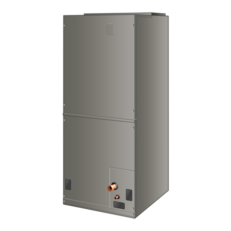
Allied A96UH2E User manual

508097-01 Issue 2039 Page 1 of 64
SERVICE MANUAL
A96UH2E
(P) 508097-01
*P508097-01*
Table of Contents
Technical Specications - A96UH2E ...........................2
Parts Arrangement.......................................................6
Electrical......................................................................7
Placement & Installation............................................21
Joint Cementing Procedure.......................................22
Venting Practices.......................................................23
Vent Piping Guidelines ..............................................24
Condensate Piping ....................................................40
Start-Up .....................................................................44
Heating System Service Checks ...............................45
Typical Operating Characteristics..............................49
Maintenance..............................................................50
Wiring Diagram..........................................................53
Electronic Ignition ......................................................54
Field Wiring Applications ...........................................56
Troubleshooting: Heating Sequence of Operation ....60
Troubleshooting: Heating Sequence of Operation
(Continued)................................................................61
Troubleshooting: Heating Sequence of Operation
(Continued)................................................................62
Troubleshooting: Cooling Sequence of Operation.....63
Troubleshooting: Continuous Fan / Accessories
Sequence of Operation..............................................64
This is a safety alert symbol and should never be ignored. When you see this symbol on labels or in manuals, be alert to
the potential for personal injury or death.
Electric shock hazard.
Can cause injury or death. Before attempting
to perform any service or maintenance,
turn the electrical power to unit OFF at
disconnect switch(es). Unit may have
multiple power supplies.
WARNING
As with any mechanical equipment, contact with sharp
sheet metal edges can result in personal injury. Take
care while handling this equipment and wear gloves
and protective clothing.
CAUTION
Improper installation, adjustment, alteration, service
or maintenance can cause property damage, personal
injury or loss of life. Installation and service must be
performed by a licensed professional HVAC installer (or
equivalent), service agency or the gas supplier.
WARNING

508097-01Issue 2039Page 2 of 64
Technical Specications - A96UH2E
MODEL NUMBER GUIDE
PHYSICAL AND ELECTRICAL DATA
Model
1st Stage 2nd Stage
AFUE
(ICUS)
Nom. Cooling
Capacity
(tons)
Gas Inlet
(in.)
Volts / Hz /
Phase
Min. Time
Delay Breaker
or Fuse
Nominal F.L.A.
Trans.
(V.A.)
Approx. Weight
(lbs.)
Input
(Btuh)
Output
(Btuh)
Input
(Btuh)
Output
(Btuh)
Upow / Horizontal
A96UH2E030B08S 20,000 19,000 30,000 29,000 96.0 2 1/2 120-60-1 15 6.8 40 130
A96UH2E045B12S 29,000 28,000 44,000 42,000 96.0 3 1/2 120-60-1 15 6.8 40 130
A96UH2E070B12S 43,000 41,000 66,000 62,000 96.0 3 1/2 120-60-1 15 6.8 40 138
A96UH2E090C16S 57,000 55,000 88,000 85,000 96.0 4 1/2 120-60-1 15 8.4 40 166
A96UH2E110C20S 72,000 70,000 110,000 105,000 96.0 5 1/2 120-60-1 15 10.9 40 174
Note: For vent length and clearances to combustibles, please reference installation instructions.
Major Revision Code
Numeric Code
Heat Exch
S = Stainless Steel Heat
Exchanger
Nom. CFM x 100
08 = 2 Ton add on cooling
12 = 3 Ton add on cooling
16 = 4 Ton add on cooling
20 = 5 Ton add on cooling
Cabinet Width
B = 17.5” width
C = 21.0” width
D = 24.5” width
A
Flagship
AFUE
96 = 96% Efficency
Configuration
UH = Upflow/Horizontal
DF = Downflow
Stages
2 = Two Stage
Blower Drive
E = High Efficiency Motor
BTUH
Heating Input x 1000
A 96 UH 2 E 110 C 20 S -01
FILTER REQUIREMENT DATA
Airow Descriptor
Disposable Filters Cleanable Filters
Minimum Area
(sq. in.)
Minimum Area
(sq.in.)
12 576 288
16 768 384
20 960 480
1. The Airflow Descriptor is the two digits following the “B”, “C”, or “D” in the model number; e.g. “20” is the Airflow Descriptor.
2. Areas shown for permanent filters are based on filters rated at 600 feet per minute face velocity.

508097-01 Issue 2039 Page 3 of 64
BLOWER DATA: UPFLOW / HORIZONTAL
A96UH2E030B08S PERFORMANCE (Less Filter)
External
Static
Pressure
in. w.c.
Air Volume / Watts at Various Blower Speeds
High Medium-High Medium Medium-Low Low
cfm Watts cfm Watts cfm Watts cfm Watts cfm Watts
0.00 1025 122 935 97 855 76 820 76 765 69
0.10 985 129 910 104 820 82 775 72 700 63
0.20 955 139 875 114 770 87 640 62 575 52
0.30 915 145 830 120 730 96 575 67 375 40
0.40 875 155 790 130 680 101 530 74 330 47
0.50 830 161 750 136 635 110 470 79 260 51
0.60 800 172 700 146 580 115 420 82 210 47
0.70 765 181 650 150 550 124 385 90 180 51
0.80 715 187 615 159 500 127 325 94 135 52
A96UH2E045B12S PERFORMANCE (Less Filter)
External
Static
Pressure
in. w.c.
Air Volume / Watts at Various Blower Speeds
High Medium-High Medium Medium-Low Low
cfm Watts cfm Watts cfm Watts cfm Watts cfm Watts
0.00 1345 340 1255 245 1150 185 895 105 845 95
0.10 1305 345 1225 250 1105 200 855 110 810 95
0.20 1290 360 1190 260 1080 205 825 120 780 105
0.30 1275 370 1150 270 1045 215 785 125 720 110
0.40 1220 385 1120 280 1015 220 735 135 690 120
0.50 1215 390 1090 290 980 230 705 140 635 125
0.60 1190 395 1060 300 950 240 650 150 600 135
0.70 N/A N/A 1015 300 900 250 620 155 555 140
0.80 N/A N/A 1000 310 870 260 580 160 520 145
A96UH2E070B12S PERFORMANCE (Less Filter)
External
Static
Pressure
in. w.c.
Air Volume / Watts at Various Blower Speeds
High Medium-High Medium Medium-Low Low
cfm Watts cfm Watts cfm Watts cfm Watts cfm Watts
0.00 1380 315 1305 250 1190 200 965 105 920 100
0.10 1360 325 1270 255 1180 205 915 115 865 100
0.20 1310 335 1250 265 1130 215 880 120 815 110
0.30 1275 340 1205 275 1100 225 835 125 775 115
0.40 1250 355 1175 280 1065 230 795 135 730 125
0.50 1215 370 1145 295 1045 240 745 145 670 130
0.60 1200 380 1100 310 995 245 705 150 640 140
0.70 1145 380 1070 310 960 255 670 160 585 145
0.80 N/A N/A 1035 320 925 265 610 165 550 155

508097-01Issue 2039Page 4 of 64
BLOWER DATA: UPFLOW / HORIZONTAL
A96UH2E090C16S PERFORMANCE (Less Filter)
External
Static
Pressure
in. w.c.
Air Volume / Watts at Various Blower Speeds
High Medium-High Medium Medium-Low Low
cfm Watts cfm Watts cfm Watts cfm Watts cfm Watts
0.00 1740 370 1505 250 1370 195 1285 160 1135 125
0.10 1695 390 1470 265 1325 205 1240 170 1090 135
0.20 1660 405 1435 280 1290 220 1195 185 1045 145
0.30 1615 415 1390 295 1240 235 1140 200 995 160
0.40 1590 425 1350 305 1200 245 1110 210 945 165
0.50 1560 440 1310 320 1155 260 1055 225 895 175
0.60 1525 455 1255 335 1105 270 1005 230 855 190
0.70 1475 470 1220 340 1065 285 960 245 805 200
0.80 N/A N/A 1170 355 1010 295 920 255 760 210
A96UH2E110C20S PERFORMANCE (Less Filter)
External Static
Pressure in. w.g.
Air Volume / Watts at Dierent Blower Speeds
Bottom Return Air, Side Return Air with Optional Return
Air Base, Return Air from Both Sides or Return Air from
Bottom and One Side.
Single Side Return Air − Air volumes in bold require eld
fabricated transition to accommodate 20 x 25 x 1 in. air
lter in order to maintain proper air velocity.
High Med-High Medium Med-Low Low High Med-High Medium Med-Low Low
cfm Watts cfm Watts cfm Watts cfm Watts cfm Watts cfm Watts cfm Watts cfm Watts cfm Watts cfm Watts
0.00 2220 645 1940 435 1765 335 1635 280 1435 200 2185 655 1915 440 1745 340 1620 275 1430 195
0.10 2170 660 1920 460 1715 350 1595 290 1380 205 2160 660 1880 460 1705 345 1570 285 1380 205
0.20 2130 680 1865 475 1670 370 1560 305 1345 220 2115 680 1835 470 1670 365 1535 305 1325 220
0.30 2095 700 1835 490 1640 390 1525 325 1285 230 2060 705 1795 495 1630 380 1505 320 1285 230
0.40 2065 720 1785 510 1600 405 1465 335 1250 245 2050 720 1760 510 1570 400 1455 330 1235 245
0.50 2030 740 1755 525 1560 415 1425 355 1215 260 2000 740 1720 530 1535 415 1410 345 1195 260
0.60 1995 760 1705 550 1525 435 1380 370 1150 270 1955 760 1685 550 1505 435 1380 365 1145 275
0.70 1955 770 1660 560 1475 450 1350 375 1100 290 1935 775 1650 555 1455 450 1325 375 1100 285
0.80 1930 790 1635 575 1445 460 1300 395 1050 305 1890 790 1610 575 1425 460 1285 390 1055 295

508097-01 Issue 2039 Page 5 of 64
ACCESSORY LIST
Kit Type Description Catalog Number
Return Air Base
Return Air Base 17.5 Inch 68W62
Return Air Base 21.0 Inch 68W63
Return Air Base 24.5 Inch 68W64
High Altitude Pressure Swiches
2-Stage 96% UH/DF (4501-7500 ft) [030, 045] 14A57
2-Stage 96% UH/DF (4501-7500 ft) [070] 14A54
2-Stage 96% UH/DF (4501-7500 ft) [90] 14A57
2-Stage 96% UH/DF (4501-7500 ft) [110] 14A46
2-Stage 96% UH/DF (4501-7500 ft) [135] 14A49
2-Stage 96% UH/DF (7501-10,000 ft) [030, 045] 14A50
2-Stage 96% UH/DF (7501-10,000 ft) [070] 14A53
2-Stage 96% UH/DF (7501-10,000 ft) [090] 14A54
2-Stage 96% UH/DF (7501-10,000 ft) [110] 14A51
High Altitude Orice Kits (7500’+)
2-Stage 96% UH/DF - Natural Gas 51W01
2-Stage 96% UH/DF [030] - Natural Gas 14C92
2-Stage 96% UH/DF - Propane Gas 78W97
2-Stage 96% UH/DF [030] - Propane Gas 14C93
LP to Natural Kits 2-Stage - 90 77W10
Downow Specic Air Filters
17.5" 51W07
21.0" 51W08
24.5" 51W09
Night Service Kits
Two Stage 10U95
Safety Night Service Kit 68W83
Horizontal Suspension Kit 80% & 90% Kit 51W10
Flush Mount Termination (90% Furnaces only)
2" & 3.0" Vent - US Version 51W11
2" & 3.0" Vent - ULC S636 Compliant (Canada) 51W12
External Filter Rack Kits
1 pack (16 x 25) 1.841018
10 pack (16 x 25) 1.841039
Downow Combustible Flooring Base
17.5" B Width 11M60
21.0" C Width 11M61
Concentric Vent Kit (90% Furnaces only) US
Only
1-1/2" Vent Version 71M80
2" Vent Version 69M29
3" Vent Version 60L46
Concentric Vent Kit (90% Furnaces only)
Canada Only
1-1/2" and 2" Vent Version 44W92
3" Vent Version 44W93
Natural To LP Kits
2-Stage 90 11K48
2-Stage 90 High Altitude (>7500') 11K47
Low Input (30K Btuh) 13X57
Twinning Kit Constant Torque Gas Furnace Twinning Kit 16W72
For vent length and clearances to combustibles, please reference installation instructions.

508097-01Issue 2039Page 6 of 64
Parts Arrangement
Figure 1.

508097-01 Issue 2039 Page 7 of 64
Electrical
ELECTROSTATIC DISCHARGE (ESD)
Precautions and Procedures
Electrostatic discharge can aect electronic
components. Take precautions to
neutralize electrostatic charge by touching
your hand and tools to metal prior to
handling the control.
CAUTION
A96UH2E unit components are shown in Figure 1. The gas
valve, combustion air inducer and burners can be accessed
by removing the access panel. Electrical components are
in the control box (Figure 2) found in the blower section.
A96UH2E units are factory equipped with a bottom return
air panel in place. The panel is designed to be eld removed
as required for bottom air return. Markings are provided for
side return air and may be cut out in the eld.
Control Box Components (Figure 2)
Transformer
Integrated Control
Interlock Switch
Circuit Breaker
Figure 2. Control Box
Transformer (T1)
A transformer located in the control box provides power
to the low voltage section of the unit. Transformers on all
models are rated 40VA with a 120V primary and a 24V
secondary.
Door Interlock Switch (S51)
A door interlock switch is wired in series with line voltage.
When the inner blower access panel is removed the unit
will shut down.
Circuit Breaker (CB8)
A 24V circuit breaker is also located in the control box. The
switch provides overcurrent protection to the transformer
(T1). The breaker is rated at 3A at 32V. If the current
exceeds this limit the breaker will trip and all unit operation
will shutdown. The breaker can be manually reset by
pressing the button on the face. See Figure 3.
Figure 3. Circuit Breaker (CB8)
PRESS TO RESET
Integrated Ignition Control (A92)
Shock hazard.
Disconnect power before servicing.
Control is not eld repairable. If control is
inoperable, simply replace entire control.
Can cause injury or death. Unsafe
operation will result if repair is attempted.
WARNING
Units are equipped with a two-stage, integrated control.
The system consists of a ignition / blower control (Figure
4 and Figure 5) with control pin designations in Table 1
and Table 2 and ignitor (Figure 12). The control and ignitor
work in combination to ensure furnace ignition and ignitor
durability. The control provides gas ignition, safety checks
and indoor blower control with two-stage gas heating.
The furnace combustion air inducer, gas valve and indoor
blower are controlled in response to various system inputs
such as thermostat signal, pressure and limit switch signal
and ame signal. The control features a seven-segment
LED display, indicating furnace status and error codes.
The LED ashes in single digits. For example, using Table
4 under LIMIT CODE, an “E” followed by “2” followed by “5”
followed by “0”, the limit switch circuit is open. The control
also has two unpowered (dry) 1/4” contacts for a humidier
and a 120 volt accessory terminal. Both rated at (1) one
amp each.

508097-01Issue 2039Page 8 of 64
Pin # Function
1Ignitor
2 Combustion Air Inducer High Speed
3 Combustion Air Inducer Low Speed
4Combustion Air Inducer Neutral
5Ignitor Neutral
Table 1. 5-Pin Terminal Designations
Pin # Function
1Gas Valve Second Stage
2 Second Stage Pressure Switch
3 Rollout Switch In
4Ground
524V Hot
6Primary Limit In
7Gas Valve First Stage
8Gas Valve Common
924V Neutral
10 Ground
11 Primary Limit Out
12 First Stage Pressure Switch
Table 2. 12-Pin Terminal Designations
Electric Shock Hazard.
Can cause injury or death. Unit must be
properly grounded in accordance with
national and local codes.
WARNING
Fire Hazard.
Use of aluminum wire with this product may result in a
re, causing property damage, severe injury or death.
Use copper wire only with this product.
WARNING
Electronic Ignition
At the beginning of the heat cycle the integrated control
monitors the rst stage and second stage combustion air
inducer pressure switch. The control will not begin the
heating cycle if the rst stage pressure switch is closed
(bypassed). Likewise the integrated control will not begin
the second stage heating cycle if the second stage
pressure switch is closed, and will remain in rst stage
heat. However, if the second stage pressure switch closes
during the rst stage heat pre-purge, the control will allow
second stage heat. Once the rst stage pressure switch
is determined to be open, the combustion air inducer is
energized on low (rst stage) heat speed. When the
dierential in the pressure switch is great enough, the
pressure switch closes and a 15-second pre-purge begins.
After the 15-second pre-purge period, the ignitor warms
up for 20 seconds after which the gas valve opens for a
4-second trial for ignition. The ignitor remains energized
during the trial until ame is sensed. If ignition is not proved
during the 4-second period, the control will try four more
times with an inter purge and warm-up time between trials
of 35 seconds. After a total of ve trials for ignition (including
the initial trial), the control goes into Watchguard-Flame
Failure mode. After a 60-minute reset period, the control
will begin the ignition sequence again.
NOTE: During abnormal conditions such as low supply
voltage or low outdoor temperatures and the low re
pressure switch does not close, the combustion air inducer
will switch to high speed. After the low & high pressure
switch close, the unit will proceed with a 15 sec pre-purge,
followed by a 20 sec ignitor warm up, then ignition on
highre. After 10 to 20 seconds of high re operation the
unit will switch to low re.
Two Stage Operation / Thermostat Selection DIP
Switch
The control can be utilized in two modes: SINGLE-STAGE
thermostat or TWO-STAGE thermostat. The thermostat
selection is made using a DIP switch and must be positioned
for the particular application. DIP switch 1, labeled T”STAT
HEAT STAGE is factory-set in the OFF position for use
with a two-stage thermostat. Move the DIP switch to ON
for use with a single stage thermostat.
While in the single-stage thermostat mode, the burners will
always re on rst-stage heat. The combustion air inducer
will operate on low speed and indoor blower will operate on
low heat speed. The unit will switch to second stage heat
after a “recognition period”. DIP switch 2, labeled SECOND
STAGE DELAY, is factory set in the OFF position for a 7
minute recognition period. The switch can be moved to the
ON position for a 12 minute recognition period, after which
time the unit will switch to second-stage heat.
While in the two-stage thermostat mode, the burners will
re on rst-stage heat. The combustion air inducer will
operate on low speed and indoor blower will operate on low
heat speed. The unit will switch to second-stage heat on
call from the indoor thermostat. If there is a simultaneous
call for rst and second stage heat, the unit will re on
rst stage heat and switch to second stage heat after 30
seconds of operation. See Sequence of Operation ow
charts in the back of this manual for more detail.

508097-01 Issue 2039 Page 9 of 64
Figure 4. Integrated Control
Flame Sense
S4 DIP Switches
24VAC Indoor
Blower Terminals
HUM ACC
Ignitor and Combustion
Air Inducer
Neutrals
On Board Links
LED
Diagnostic Push
Button
3/16” QUICK CONNECT TERMINALS
FLAME SENSE SIGNAL
HI COOL 24VAC
LO COOL 24VAC
LO HEAT 24VAC
PARK
PARK
COMMON 24VAC
1/4” QUICK CONNECT TERMINALS
NEUTRALS = 120 VAC NEUTRAL
HUM = UNPOWERED NORMALLY OPEN (DRY) CONTACTS
LI = 120VAC INPUT TO CONTROL
A
CC = 120VAC OUTPUT TO OPTIONAL ACCESSORY
THERMOSTAT CONNECTIONS (TB1)
DS = DEHUMIDIFICATION SIGNAL
W2 = HEAT DEMAND FROM 2ND STAGE TSTAT
W1 = HEAT DEMAND FROM 1ST STAGE TSTAT
R = CLASS 2 VOLTAGE TO TSTAT
G = MANUAL FAN FROM TSTAT
C = TSTAT SIGNAL GROUND CONNECTED TO
TRANSFORMER GRD (TR) & CHASSIS GROUND (GRD)
Y1 = TSTAT 1ST STAGE COOL SIGNAL
Y2 = TSTAT 2ND STAGE COOL SIGNAL
O = TSTAT SIGNAL TO HEAT PUMP REVERSING VALVE
DH = NOT USED
L = NOT USED

508097-01Issue 2039Page 10 of 64
Figure 5. Integrated Control Conguration Guide
HEATING BLOWER−OFF DELAY
60 SECOND
HTG BLOWER
OFF DELAY
120 SECOND
HTG BLOWER
OFF DELAY
180 SECOND
HTG BLOWER
OFF DELAY
FLAME
15
HSI/CAI
2ND STAGE HEAT ON DELAY
7 MIN
UPSTAGE
DELAY
12 MIN
UPSTAGE
DELAY
*
W915
2 STAGE
COMPR
1−STG COMPRESSOR
2−STAGE
COMPRESSOR LINK
(JUMPERS Y1 to Y2)
W915
DO NOT CUT
2−STG COMPRESSOR
HEAT PUMP LINK
(JUMPERS R to O)
W951
(JUMPERS R to DS)
W914
W915
2 STAGE
COMPR
CUT LINK
A/C UNIT
DO NOT CUT
HEAT PUMP UNIT
CUT LINK
W951
HEAT
PUMP
W951
HEAT
PUMP
W914
DEHUM
NO SIGNATURESTAT
W/ DS CONNECTION
DO NOT CUT
SIGNATURESTAT W/
DS CONNECTION
CUT LINK
W914
DEHUM
1
1
1
ON−BOARD LINK
OPTION SELECTION
1234567
1234567
123567
4
123567
4
NEUTRALS
L1
ACC
HUM
14
36
P79
110
312
J2
4 7
W915
2 STAGE
COMPR
W951
HEAT
PUMP
W914
DEHUM
CUT FOR
OPTION
SELECTION
123456
ON
SureLight
W1W2 GY2 Y1 CC DH LODSR
W1
W2
G
Y2
Y1
C
C
R
L
DH
7
1
ON
ON
ON
ON
90 SECOND
HTG BLOWER
OFF DELAY
*1234567
ON
1234567
ON
THERMOSTAT SELECTION
1−STAGE
THERMOSTAT
(TIMED STAGING)
−SEE SW #2
TWO STAGE
THERMOSTAT
*
1234567
1234567
ON
ON
−BLOWER ON DELAY − 30 SEC. FIXED
1234567
ON
SENSE
IGN
CAI2
CAI1
N
N
J3
S1
S4S3
DIAGNOSTIC
LED
DIAGNOSTIC
PUSH BUTTON
*45 SECOND
COOL BLOWER
OFF DELAY
2 SECOND
COOL BLOWER
OFF DELAY
123567
4
123567
4
ON
ON
COOLING BLOWER-OFF DELAY
1234567
ON
1234567
ON
1234567
ON
CONTINUOUS FAN SETTINGS
LOW HEAT SPEED
LOW COOL SPEED
HIGH HEAT SPEED
HIGH COOL SPEED
DEHUMIFICATION LINK
- CUT ON-BOARD LINK (SOLDER TRACE)
COMPLETELY THROUGH BOTH LAYERS ON THE
CONTROL BOARD
- LINKS CUT IN ERROR - INSTALL A JUMPER ON THE
APPROPRIATE TERMINALS ON THE TERMINAL
STRIP
- PROTECTIVE PLASTIC FILM ON DIP SWITCHES
MAY BE REMOVED FOR EASE IN SETTING OF DIP
SW.
* FACTORY DEFAULT

508097-01 Issue 2039 Page 11 of 64
Display Action (when button released)
No change (idle)* Remain in idle mode
Solid “E” Enter diagnostic recal mode
Solid “F” Enter ame signal mode
* No change implies the display will continue to show whatever is currently being displayed for normal operation (blinking decimal,
active error code, heat state, etc.)
Table 3. Integrated Control Diagnostic Modes
Code Diagnostic Codes/Status of Equipment Action Required to Clear and Recover
.Idle mode (Decimal blinks at 1 Hertz -- 0.5
second ON, 0.5 second OFF).
CCooling stage (1 second ON, 0.5 second OFF)
1 or 2 displayed / Pause / Repeat codes.
d Dehumidication mode (1 second ON, 1
second OFF) / Pause / Repeat Codes).
H Gas Heat Stage (1 second ON, 0.5 second
OFF) 1 or 2 displayed / Pause / Repeat codes.
Blinking during ignition.
hHeat pump stage.
E110 Low line voltage. Line Voltage Low (Voltage lower than nameplate rating). Check power line
voltage and correct. Alarm clears 5 seconds after fault recovered.
E111 Line voltage polarity reversed. Reverse line power voltage wiring. System resumes normal operation 5
seconds after fault recovered.
E112 Ground not detected. System shuts down. Provide proper earth ground. System resumes normal
operation 5 seconds after fault recovered.
E113 High line voltage. Line Voltage High (Voltage higher than nameplate rating). Provide power
voltage within proper range. System resumes normal operation 5 seconds
after fault recovered.
E114 Line voltage frequency out-of-range. No 60 Hertz Power. Check voltage and line power frequency. Correct
voltage and frequency problems. System resumes normal operation 5
seconds after fault recovered.
E115 Low 24V - Control will restart if the error
recovers.
24-Volt Power Low (Range is 18 to 30 volts). Check and correct voltage.
Check for additional power-robbing equipment connected to system. May
require installation of larger VA transformer to be installed in furnace / air
handler. Clears after fault recovered.
E117 Poor ground detected (Warning only) Provide proper grounding for unit. Check for proper earth ground to the
system. Warning only will clear 30 seconds after fault recovered.
E125 Control failed self-check, internal error,
failed hardware. Will restart if error recovers.
Integrated control not communicating. Covers
hardware errors (ame sense circuit faults, pin
shorts, etc.).
Hardware problem on the control. Cycle power on control. Replace if
problem prevents service and is persistent. Critical alert. Cleared 300
seconds after fault recovered.
E200 Hard lockout - Rollout circuit open or previously
open.
Correct cause of rollout trip, or replace ame rollout switch. Test furnace
operation. Cleared after fault recovered.
E204 Gas valve mis-wired. Check gas valve operation and wiring. Clears when repaired.
E205 Gas valve control relay contact shorted. Check wiring on control and gas valve. If wiring is correct, replace control.
E206 Gas valve second-stage relay failure. Furnace will operate on 1st stage for remainder of the heating demand.
Will clear after fault recovered. If unable to operate 2nd stage, replace
control.
E207 Hot surface ignitor sensed open. Measure resistance of hot surface ignitor. Replace if open or not within
specied range found in IOM. Resumes normal operation after fault is
cleared.
Table 4. Integrated Diagnostic Codes / Status of Equipment

508097-01Issue 2039Page 12 of 64
Code Diagnostic Codes/Status of Equipment Action Required to Clear and Recover
E223 Low pressure switch failed open. Check pressure (inches w.c.) of low pressure switch closing on heat call.
Measure operating pressure (inches w.c.). Inspect vent and combustion
air inducer for correct operation and restriction. Resumes normal operation
after fault is cleared
E224 Low pressure switch failed closed. Check operation of low pressure switch to see if it is stuck closed on
heat call longer than 150 seconds. Measure operating pressure (inches
w.c.). Inspect vent and combustion air inducer for correct operation and
restriction. Resumes normal operation after fault is cleared.
E225 High pressure switch failed open. Check pressure (inches w.c.) of high pressure switch closing on heat call.
Measure operating pressure (inches w.c.). Inspect vent and combustion air
inducer for correct operation and restriction. Resumes normal operation
after fault is cleared.
E226 High pressure switch failed closed. Check operation of high pressure switch closing on heat call. Measure
operating pressure (inches w.c.). Inspect vent and combustion air inducer
for correct operation and restriction. Resumes normal operation after fault
is cleared.
E227 Low pressure switch open during trial for
ignition or run mode.
Check pressure (inches w.c.) of low pressure switch closing on heat call.
Measure operating pressure (inches w.c.). Inspect vent and combustion
air inducer for correct operation and restriction. Resumes normal operation
after fault is cleared.
E229 Ignition on High Fire - Information Only. Code is displayed if 1) low pressure switch fails to close, then furnace will
switch to high speed inducer to close both low and high pressure switches,
then furnace lights on high re, or 2) if continuous fan is active, furnace
lights on high re for 60 seconds to improve heat exchanger warm up time.
E240 Low ame current - Run mode. Check micro-amperes of ame sensor using control diagnostics or eld-
installed mode. Clean or replace sensor. Measure voltage of neutral to
ground to ensure good unit ground. Alert clears after current heat call has
been completed.
E241 Flame sensed out of sequence - Flame still
present.
Shut o gas. Check for gas valve leak. Replace, if necessary. Alert clears
when fault is recovered.
E250 Limit switch circuit open. Check for proper ring rate on furnace. Ensure there is no blockage in
heater. Check for proper air ow. If limit not closed within 3 minutes, unit will
go into 1-hour soft lockout. Resumes normal operation after fault is cleared.
E270 Soft lockout - Exceeded maximum number of
retries. No ame current sensed.
Check for proper gas ow. Ensure that ignitor is lighting burner. Check
ame sensor current. Clears when heat call nishes successfully.
E271 Soft lockout - Exceeded maximum number of
retries. Last retry failed due to the pressure
switch opening.
Check pressure (inches w.c.) of low pressure switch closing on heat call.
Measure operating pressure (inches w.c.). Inspect vent and combustion air
inducer for correct operation and restriction. Clears when heat call nishes
successfully.
E272 Soft lockout - Exceeded maximum number
of recycles. Last recycle due to the pressure
switch opening.
Check operation of low pressure switch to see if it is stuck closed on
heat call. Check pressure (inches w.c.) of high pressure switch closing
on heat call. Measure operating pressure (inches w.c.). Inspect vent and
combustion air inducer for correct operation and restriction. Clears when
heat call nishes successfully.
E273 Soft lockout - Exceeded maximum number of
recycles. Last recycle due to ame failure.
Check micro-amperes of ame sensor using control diagnostics or eld-
installed mode. Clean or replace sensor. Measure voltage of neutral
to ground to ensure good unit ground. Clears when heat call nishes
successfully.
E274 Soft lockout - Exceeded maximum number of
recycles. Last recycle failed due to the limit
circuit opening or limit remained open longer
than 3 minutes.
Shut down system. 1-hour soft lockout. Check ring rate and air ow.
Check for blockage. Clears when heat call nishes successfully.
E275 Soft lockout - Flame sensed out of sequence.
Flame signal is gone.
Shut o gas. Check for gas valve leak. 1-hour soft lockout. Clears when
ame has been proven stable.
E290 Ignitor circuit fault - Failed ignitor or triggering
circuitry.
Measure resistance of hot surface ignitor. Replace if open or not within
specications. 1-hour soft lockout. Clears when ame has been proven
stable.
Table 4. Integrated Diagnostic Codes / Status of Equipment

508097-01 Issue 2039 Page 13 of 64
Diagnostic LED (Figure 4)
The seven-segment diagnostic LED displays operating
status, error codes and other information. Table 4 lists
diagnostic LED codes.
Diagnostic Push Button (Figure 4)
The diagnostic push button is located adjacent to the seven-
segment diagnostic LED. This button is used to enable
the Error Code Recall “E” mode and the Flame Signal “F”
mode. Press the button and hold it to cycle through a menu
of options. Every ve seconds a new menu item will be
displayed. When the button is released, the displayed item
will be selected. Once all items in the menu have been
displayed, the menu resumes from the beginning until the
button is released.
Error Code Recall Mode
Select ”E” from the menu to access the most recent 10
error codes. Select “c” from the Error Code Recall menu
to clear all error codes. Button must be pressed a second
time while “c” is ashing to conrm command to delete
codes. Press the button until a solid “≡” is displayed to exit
the Error Code Recall mode.
Flame Signal Mode
Select ”F” from the menu to access the ame signal mode.
The integrated control will display the ame current on
seven-segment LED in in micro amps (uA).
Flame signal mode is exited after any of the following:
• Power is reset
• Pressing and holding push button until 3 horizontal
lines “≡” are displayed
• 10 minutes after entering the ame sense mode.
Integrated Control DIP Switches
A96UH2E units are equipped with a two-stage integrated
control. This control manages ignition timing, heating
mode fan o delays and indoor blower speeds based on
selections made using the control dip switches and jumpers.
The control includes an internal watchguard feature which
automatically resets the ignition control when it has been
locked out. After one hour of continuous thermostat
demand for heat, the watchguard will break and remake
thermostat demand to the furnace and automatically reset
the control to relight the furnace.
Heating Operation DIP Switch Settings
Switch 1 -- Thermostat Selection -- This unit may be
used with either a single-stage or two-stage thermostat.
The thermostat selection is made using a DIP switch which
must be properly positioned for the particular application.
The DIP switch is factory-positioned for use with a twostage
thermostat. If a single-stage thermostat is to be used, the
DIP switch must be repositioned.
a. Select “OFF” for two-stage heating operation
controlled by a two-stage heating thermostat
(factory setting);
b. Select “ON” for two-stage heating operation
controlled by a single-stage heating thermostat.
This setting provides a timed delay before second-
stage heat is initiated.
Switch 2 --- Second Stage Delay (Used with Single-
Stage Thermostat Only) -- This switch is used to determine
the second stage on delay when a single-stage thermostat
is being used. The switch is factory-set in the OFF position,
which provides a 7-minute delay before second-stage heat
is initiated. If the switch is toggled to the ON position, it
will provide a 12-minute delay before second-stage heat is
initiated. This switch is only activated when the thermostat
selector jumper is positioned for single-stage thermostat
use.
Indoor Blower Operation DIP Switch Settings
Switches 3 and 4 -- Heating Mode Blower-O Delay --
The blower-on delay of 30 seconds is not adjustable. The
blower-o delay (time that the blower operates after the
heating demand has been satised) can be adjusted by
moving switches 3 and 4 on the integrated control. The
unit is shipped from the factory with a blower-o delay
of 90 seconds. The blower o delay aects comfort and
is adjustable to satisfy individual applications. Adjust
the blower o delay to achieve a supply air temperature
between 90° and 110°F at the exact moment that the blower
is de-energized. Longer o delay settings provide lower
supply air temperatures; shorter settings provide higher
supply air temperatures. Table 5 provides the blower o
timings that will result from dierent switch settings.
Blower O Delay
(seconds) Switch 3 Switch 4
60 On O
90 (Factory) O O
120 O On
180 On On
Table 5. Blower O Heating Mode Delay Switch
Settings

508097-01Issue 2039Page 14 of 64
Switch 5 -- Cooling Mode Blower-O Delay -- The unit
is shipped from the factory with the dip switch positioned
OFF for a 45 second delay. Table 6 provides the cooling
mode o delay settings.
Blower O Delay
(seconds) Switch 5
45 (Factory) O
2 On
Table 6. Blower O Cooling Mode Delay Switch
Settings
Switches 6 and 7 -- Continuous Fan Mode -- Continuous
fan speed can be controlled by changing DIP switch
positions. Table 7 provides DIP switch settings for
continuous fan mode.
Continuous Fan
Mode Switch 6 Switch 7
Low Heat Speed
(Factory) O O
Low Cool Speed O On
High Heat Speed On O
High Cool Speed On On
Table 7. Continuous Fan Mode Settings
Onboard Links
W914 Dehum
Onboard link W914, is a clippable connection between
terminals R and DS on the integrated control. W914 must
be cut when the furnace is installed with a thermostat which
features humidity control. If the link is not cut, terminal “DS”
will remain energized not allowing the blower to reduce to
low cool speed upon a call for dehumidication.
W951 Heat Pump (R to O)
Onboard link W951 is a clippable connection between
terminals R and O on the integrated control. W951 must
be cut when the furnace is installed in applications which
include a heat pump unit and a thermostat which features
dual fuel use. If the link is left intact, terminal “O” will remain
energized eliminating the HEAT MODE in the heat pump.
W915 2 Stage Compr (Y1 to Y2)
Onboard link W915 is a clippable connection between
terminals Y1 and Y2 on the integrated control. W915 must
be cut if two-stage cooling will be used. If the Y1 to Y2
link is not cut the outdoor unit will operate in second-stage
cooling only.
If any onboard link is cut by mistake, install a jumper
across the corresponding terminals on the low voltage
terminal strip. Do not replace control.
IMPORTANT
Blower Compartment
Each blower is statically and dynamically balanced as
an assembly before installation in the unit.
IMPORTANT
A96UH2E units are equipped with a constant torque ECM
motor. It has a DC motor coupled to an electronic control
module both contained in the same motor housing. The
motor is programmed to provide constant torque at each of
the ve selectable speed taps. Each tap requires 24 volts
to energize.
Input Voltage Requirements
The circuit is designed to be operated with AC voltage. To
enable a tap requires 12 to 33VAC. Expected current draw
will be less than 20mA.
Troubleshooting the Motor
Troubleshooting the motor is an easy process. Follow
steps below.
1. Shut o power to unit.
2. Remove input plugs P48 and P49 from motor. See
Figure 10 for troubleshooting procedure.
If correct voltage is present in tests 1 and 2 and motor is
not operating properly, replace motor. The motor is not eld
repairable.
If replacing the indoor blower motor or blower wheel is
necessary, placement is critical. The blower wheel must
be centered in the blower housing as shown in Figure 6.
When replacing the indoor blower motor the set screw
must be aligned and tightened with the motor shaft as
shown in Figure 7.
Figure 6. Blower Wheel Replacement
Center Blower Wheel
in Blower Housing

508097-01 Issue 2039 Page 15 of 64
Figure 7.
Set Screw
Housing Hub
ALIGN AND TIGHTEN SET SCREW WITH
FLAT SIDE OF MOTOR SHAFT
Motor
Shaft
Testing the Motor (Figure 8)
If any motor fails the below tests, do not install the new
control module. The motor is defective and it also must be
replaced. The new control can fail if placed on a defective
motor.
1. Using an ohmmeter check the resistance from any
one of the motor connector pins to the aluminum end
plate of the motor. This resistance should be greater
than 100k ohms.
2. Check the resistances between each of the three motor
connector pins. These should all read approximately
the same resistance within an ohm.
3. Check to see if the blower wheel spins freely.
Figure 8. Motor Test
Scale Measurement Range in Words ohms
2 M two megohms - two million ohms 0 - 2,000,000
200 K two hundred kil-ohms -
two hundred thousand ohms 0 - 200,000
20 K twenty kilo-ohms -
twenty thousand ohms 0 - 20,000
2 K two kilo-ohms -
two-thousand ohms 0 - 2,000
200 two hundred ohms 0 - 200
Motor Module Installation
All replacement motor control modules look similar;
however, each module is designed for a specic motor
size. It is very important to make sure that you are using the
correct replacement motor control module. USE OF THE
WRONG MOTOR CONTROL MODULE MAY RESULT IN
UNEXPECTED UNIT OPERATION.
1. Verify electrical power to unit is disconnected.
2. Connect three-wire harness from motor to control
module.
3. Mount new motor
control module to
motor using two hex
head bolts. Torque
bolts to 22 inch pounds
or 1/16th clock turn as
exampled to the right.
12
3
4
5
6
7
8
9
10
11 12
1/16
TURN
4. Reconnect the two
harnesses to the motor
control module.
5. The electrical connectors of the motor should be
facing down to form a drip loop (Figure 9). This will
directs moisture away from the motor and its electric
connections on the motor.
Figure 9. Drip Loop
CONNECTOR
ORIENTATION
BETWEEN 4 AND 8
O'CLOCK
BACK OF CONTROL
MODULE
DRIP LOOP

508097-01Issue 2039Page 16 of 64
Figure 10.
1
2
3
4
5
C
L
G
N
Multi−Meter
(set to VAC)
P48
P49 24
Test 1
Test 2
Test 3 (if necessary)
Test 4 (if necessary)
1
2
3
4
5
C
L
G
N
Multi−Meter
(set to VAC)
P48
P49
120
120
Multi−Meter
(set to VAC)
120
120
24
Multi−Meter
(set to VAC)
Turn on power to unit. Check for 120 volts across terminals
“L” and “N” on input plug P48. If voltage is present continue
to test 2. If voltage is not present, problem may be upstream
of plug P48 and proceed to test 3.
Check for 120 volts across terminals “L1” and “Neutrals” on
the integrated control. If voltage is present, problem is with
the harness. If voltage is not present problem may be may
be with the integrated control.
Switch thermostat to CONTINUOUS FAN MODE. Check for
24 volts across terminal “C” on input plug P48 and speed
tap used for continuous fan (1, 2, 3, 4 or 5) on input plug
P49. If 24 volts is not present, problem may be upstream of
plug P49. Proceed to test 4.
Check for 24 volts across terminals “24 COM” and the
“active speed trap” on the integrated control. If voltage is
present, problem is with the harness. If voltage is not
present, problem may be may be with the integrated
control.

508097-01 Issue 2039 Page 17 of 64
Heating Components
Ignitor
The ignitor is made of durable silicon nitride. The integrated
control provides 120 volts to the ignitor for a consistent
ignition and long ignitor life. Ohm value should be 39 to 70.
See Figure 12 for ignitor location and Figure 13 for ignitor
check out.
NOTE: The A96UH2E furnace contains electronic
components that are polarity sensitive. Make sure that the
furnace is wired correctly and is properly grounded.
Flame Sensor
A ame sensor is located on the left side of the burner
support. See Figure 12. The sensor tip protrudes into the
ame envelope of the left-most burner. The sensor can
be removed for service without removing any part of the
burners. During operation, ame is sensed by current
passed through the ame and sensing electrode. The
control allows the gas valve to remain open as long as
ame signal is sensed. To check ame sense signal use
the push-button found on the integrated control and go to
Field Test Mode. The menu will display the ame signal.
See Table 8 for ame signal.
Normal Low Drop Out
2.6 or greater 2.5 or less 0.6
Table 8. Flame Signal in Microamps
Gas Valve
The valve (Figure 12) is internally redundant to assure
safety shut-o. If the gas valve must be replaced, the same
type valve must be used.
24VAC terminals and gas control knob are located on the
valve. A wire harness connects the terminals from the gas
valve to the electronic ignition control. 24V applied to the
terminals energizes the valve.
Inlet and outlet pressure taps are located on the valve. A
regulator adjustment screw is located on the valve.
LPG change over kits are available from Allied. Kits include
burner orices and a gas valve.
Flame Rollout Switches (S47)
Flame rollout switch is a high temperature limit located on
top of the burner box, one on each side.- See Figure 12.
The limit is a N.C. SPST manual-reset limit. When S47
senses rollout, the circuit breaks and the ignition control
immediately stops ignition and closes the gas valve.
Rollout can be caused by a blocked exchanger, ue or lack
of combustion air. The switch is factory set to trip (open) at
210°F and cannot be adjusted. The switch can be manually
reset. To manually reset a tripped switch, push the reset
button located on the control.
Burners
All units use inshot burners. Burners are factory set and
require no adjustment. Always operate the unit with the
burner box front panel in place. Each burner uses an orice
that is precisely matched to the burner input. Burners can
be removed as a one piece assembly for service. If burner
assembly has been removed, it is critical to align center
of each burner to the center of the clamshell when re-
installing. See more detail in Section VI- MAINTENANCE.
Primary Limit Control (S10)
The primary limit (S10) is located in the heating vestibule
panel. When excess heat is sensed in the heat exchanger,
the limit will open. If the limit is open, the furnace control
energizes the supply air blower and closes the gas valve.
The limit automatically resets when unit temperature
returns to normal. The switch must reset within three
minutes or the control will go into Watch guard for one
hour. The switch is factory set and cannot be adjusted.
The switch may have a dierent set point for each unit
model number. When removing switch make note of
orientation. When replacing switch make sure the three
mounting holes are lined up with the screw holes in the
vestibule for correct orientation.
Figure 11. Primary Limit Control (S10)
Mounting Hole
Mounting Hole
Mounting Hole

508097-01Issue 2039Page 18 of 64
Figure 12. Heating Components
Intake Air Top Cap
Sensor
Rollout Switch
Rollout Switch
Burner Assembly
Ignitor
Manifold And Gas Orifices
Two-Stage Gas Valve
Burner Box Cover

508097-01 Issue 2039 Page 19 of 64
Figure 13. Ignitor Check
Test 1
Check ignitor circuit for correct resistance.
Remove 5-pin plug from control.
Check ohms reading across terminals 1 and 5.
Reading should be between 39 and 70 ohms. If
value is correct, this is the only test needed.
If the reading on the meter is not correct, (0 or
infinity) then a second test is needed.
Test 2
Check ignitor for correct resistance.
Seperate the 2-pin jack-plug near the manifold and check
resistance of ignitor at the plug. Reading should be
between 39 and 70 ohms. If the reading is correct, then
the problem is with the wiring between the jack-plug and
the control. If reading is not correct, the issue is the ignitor.
Test 3
Check ignitor for correct voltage
Insert meter probes into terminals 1 and 5 (use small
diameter probes in order not to damage plug).
Check voltage during 20 second ignitor warm up period.
Voltage should read 120 volts +10%. If voltage reads below
these values, check for correct supply voltage to furnace.
Meter
(set to ohms)
Meter
(set to ohms)
Meter
(set to AC volts)
Integrated Control Detail

508097-01Issue 2039Page 20 of 64
Combustion Air Inducer (B6) and Cold End Header Box
All A96UH2E units use a two-speed combustion air inducer
to move air through the burners and heat exchanger during
heating operation. The blower uses a 120VAC motor.
The motor operates during all heating operation and is
controlled by integrated control control A92. The inducer
also operates for 15 seconds before burner ignition (pre-
purge) and for 5 seconds after the gas valve closes (post-
purge). The inducer operates on low speed during rst-
stage heat, then switches to high speed for second stage
heat.
The combustion air inducer is installed on the cold end
header box (CEHB). The cold end header box is a single
piece made of hard plastic. The box has an internal
channel where the combustion air inducer creates negative
pressure at unit start up. The channel contains an orice
used to regulate ow created by the combustion air inducer.
The box has pressure taps for the combustion air inducer
pressure switch hoses. The pressure switch measures the
pressure dierential across the cold end header box orice
or dierence in the channel and the box. If replacement
is necessary the gaskets used to seal the box to the
vestibule panel and the combustion air inducer to the
box, must also be replaced.
A pressure switch measures the pressure dierential across
the CEHB orice to prove inducer operation. The CEHB
orice will be dierent for each model. When the proving
switch opens, the furnace control (A92) immediately closes
the gas valve to prevent burner operation.
Combustion Air Inducer Pressure Switch (S18) (Figure
14)
A96UH2E series units are equipped with a dual combustion
air pressure switch (rst and second stage) located on the
CEHB. The switch is connected to the cold end header box
by means of exible silicone hoses. It monitors negative
dierential pressure across the cold end header box orice.
The switches are a single-pole single-throw pressure
switches electrically connected to the integrated control.
The purpose of the switches is to prevent burner operation
if the combustion air inducer is not operating, the inlet or
exhaust pipes or heat exchanger are restricted.
On heat demand (rst or second stage) the switch senses
that the combustion air inducer is operating. It closes a
circuit to the integrated control when pressure across the
CEHB orice becomes greater then the switch set point.
Set points vary depending on unit size. See Table 9. Both
pressures sensed by the switches are negative relative to
atmospheric pressure. If the inlet or exhaust pipes, or the
heat exchanger become obstructed, the switch senses the
loss of dierential pressure and opens the circuit to the
furnace integrated control and gas valve. A bleed port on
the switch allows relatively dry air in the vestibule to purge
switch tubing, to prevent condensate build up.
Figure 14. Combustion Air Inducer Pressure Switch
3/16 Terminals
Low Fire Switch
High Fire Switch
1/4" Terminals
Tap (negative - ) Tap (positive +)
NOTE: The switch is factory set and is not eld adjustable.
It is a safety shut-down control in the furnace and must
not be by-passed for any reason. If switch is closed or
bypassed, the control will not initiate ignition at start up.
Unit Set Point Low Heat Set Point High Heat
030, 045 0.40 0.70
070 0.50 0.85
090 0.50 0.85
110 0.50 0.90
Table 9. 0 - 4,500 ft.
Table of contents
Other Allied Air Handler manuals
Popular Air Handler manuals by other brands

AIR-TRANSFER
AIR-TRANSFER AT1200HBEC user manual

Trox Technik
Trox Technik X-CUBE compact installation manual

Swegon
Swegon ESENSA PX TOP 05 installation instructions

Mars
Mars Century Comfort-Aire HRG18 S1P Series Service manual

Salda
Salda Smarty 2XV 1.1 MOUNTING AND INSTALLATION INSTRUCTION

NovingAIR
NovingAIR BASE 150 Instruction and maintenance manual

Daikin
Daikin Altherma 3 H HT ECH2O Series Service manual

Salda
Salda RIS 1900 VEL EKO 3.0 QUICK LAUNCH GUIDE

Trane
Trane 2TEE3C31A1000A Installer's guide

Daikin
Daikin DCG090 manual

VTS Medical Systems
VTS Medical Systems Ventus Compact VVSc Series Quick start up guide

Cando
Cando HOLD-RITE Assembly instructions