Allied SX-190 User manual


TECHNICAL SPECIFICATION
Basic Frequency Coverage
*Additional Band ............................................................500 KHz band width
*Crystal not supplied.......................................................3.5 to 10 MHz
80 meter Band.................................................................3.5 to 4.0 MHz
49 meter Band.................................................................5.7 to 6.2 MHz
40 meter Band (HAM) ....................................................7.0 to 7.5 MHz
31 meter Band (WWV@ 10 MHz)..................................9.5 to 10.0 MHz
25 meter Band.................................................................11.5 to 12.0 MHz
20 meter Band (HAM) ....................................................14.0 to 14.5 MHz
19 meter Band (WWV@15 MHz)...................................15.0 to 15.5 MHz
16 meter Band.................................................................17.5 to 18.0 MHz
11 meter Band (CB) ........................................................27.0 to 27.5 MHz
*Crystal not supplied.......................................................10.0 to 30.0 MHz
Number of semiconductors....4 FET, 22 TR, 13 diodes, 2 zeners and 2 thermisters
IF. Frequencies......................2.420 MHz to 2.920 MHz (Variable) and 455 KHz
Reception ..............................AM, CW, and Single sideband (SSB)
Sensitivity - AM....................Less than 1 microvolt for 10 db S/N ratio
Sensitivity SSB/CW..............Less than 0.5 microvolt for 10 db S/N ratio
Selectivity..............................4 KHz at 6 db down
Visual dial accuracy..............±200 Hz
Calibration accuracy..............Better than ±500 Hz adjacent 25 KHz calibration points after
indexing
Stability.................................Better than 500 Hz after warm-up
Image rejection......................More than 60 db
Spurious rejection..................More than 50 db
Rejection tuning....................More than 40 db
Selection tuning.....................500 Hz at -3db
Audio output power...............Maximum 1 watt at 8-ohm load
Audio output impedance........8 ohm and 600 ohm
Headphone output .................8 ohm, panel-mounted jack accepts standard 1/4-inch plug
Antenna input impedance......50 ohm to 75 ohm unbalanced: rear mounted type SO-239 coaxial
receptacle accepts PL-259 connector
Power source.........................120 volt AC 60 Hz and 12V DC negative ground only
Power consumption...............10 watts
Remote stdby control.............Rear-mounted; 2 pin connector
Dimensions............................7" high, 15" wide and 10" deep
- 1 -

GENERAL DESCRIPTION
The SX-190 SHORTWAVE RECEIVER is fully transistorized and offers a new high in reliabil-
ity, selectivity, and drift free operation. It covers the 49 thru 16-meter international broadcasting
bands plus the 11-meter CB band and WWV at 10 and 15 MHz. Two blank positions are left for
the owner who may by the addition of the proper crystal, cover any 500 KHz wide segment of
frequency between 3.5 thru 10 MHz and 10.0 thru 30.0 MHz. These bands are selectable with the
front panel band selector switch.
Its circuitry uses 4 FETS, 22 transistors, 13 diodes, 2 thermistors and 2 zener regulators. Dual
conversion and mechanical filters enhance the excellent image and spurious rejection plus sharp
selectivity of this receiver.
The suppression of unwanted heterodynes and interfering carriers is enhanced by the Q-
MULTIPLIER, which provides better than 40 dB of attenuation.
The use of a PRESELECTOR assures maximum sensitivity and a high signal to noise ratio for
outstanding reception of weak signals. The tuning dial features anti-backlash construction. It is
direct reading to 1 KHz. Precise tuning of all signals including SSB is assured by the large easy
to read dial. Superior stability is obtained by the use of a crystal controlled 1st local oscillator
and a VFO 2nd oscillator. A dual frequency calibrator (25 and 100 KHz), crystal controlled, is
used for calibrating the dial readout to an accuracy of better than ±200Hz.
The SX-190 is equipped with a crystal controlled Beat Frequency Oscillator (BFO) for the recep-
tion of USB, LSB and CW signals.
Incorporated in its circuitry are AGC, ANL and S-meter functions. The AGC (Automatic Gain
Control) has been tailored to produce minimum audio output changes even with large variations
of input signal levels. ANL (Automatic Noise Limiter) operation is achieved through the use of a
diode. When pulse type interference accompanies an incoming signal, the diode in the ANL cir-
cuit operates in a cutoff mode for very brief time intervals, thus it effectively acts as a gate to
shut out undesirable noise peaks. The S-METER indicates incoming signal strength and also acts
as a tuning aid by indicating peak signal.
A dual power supply operates from a source of 110-120 volts 60 Hz AC or 12 volts DC. On AC,
a 1-ampere fuse in the secondary of the power transformer is used for protection of the equip-
ment. The B+ power supply uses a full wave rectifier and a stabilized regulator.
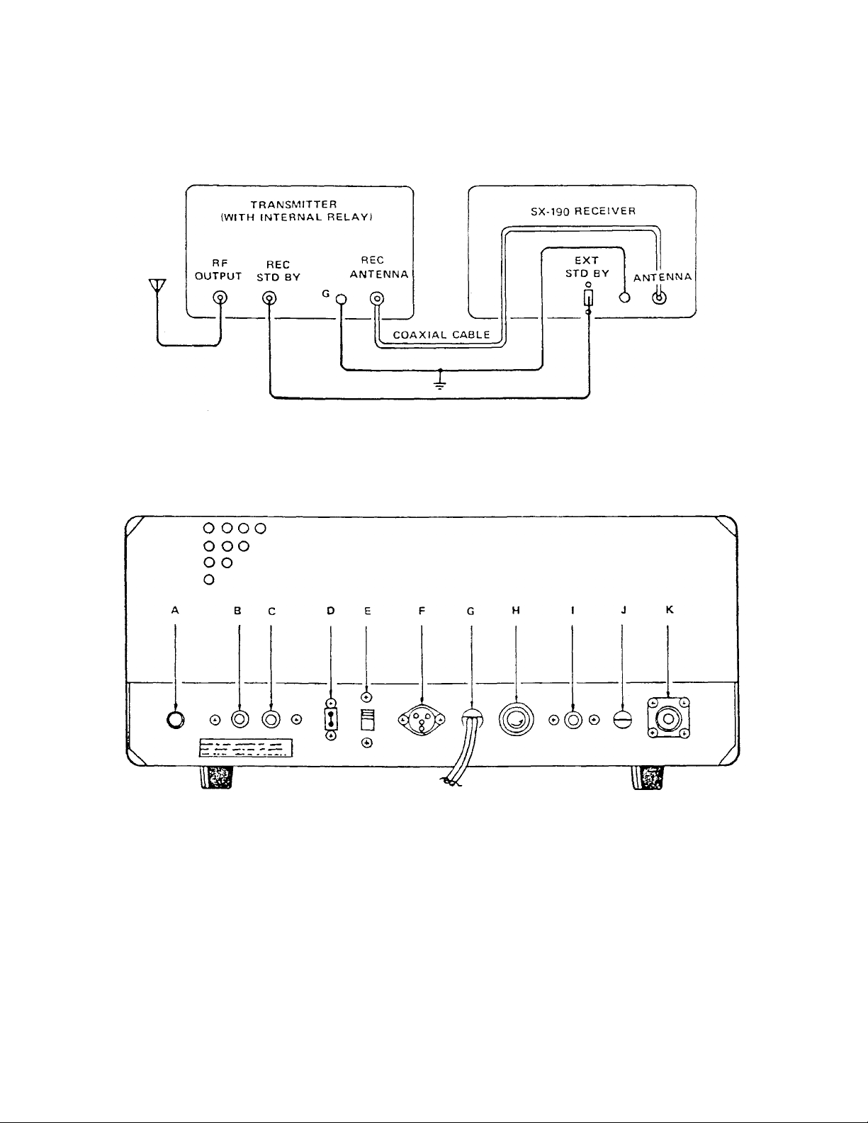
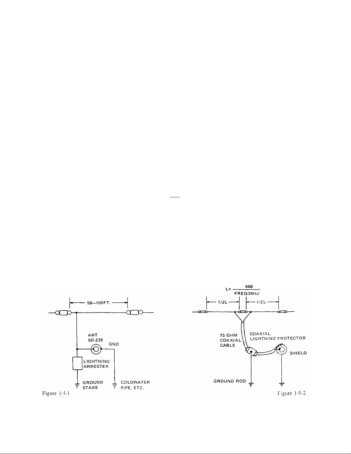
The antenna input is designed to operate with a wide variety of 50-75 ohm antennas. Both
speaker and headphone jacks are provided (8 ohm). For use with a companion transmitter, mut-
ing connections are available at the rear panel along with both HFO and VFO outputs.
Rugged mechanical construction plus modularized design provide for maximum mechanical sta-
bility and ready access to either the top or bottom of the SX-190. This allows for maximum ease
of maintenance or alignment should either become necessary.
-2-

SECTION 1: INSTALLATION
1.1 UNPACKING
Immediately after receipt of the receiver it should be removed from the shipping carton and visu-
ally inspected to insure that it has not been damaged in shipment. If it is determined that the re-
ceiver has been damaged in transit the shipping carton and packing material should be saved and
the transportation company notified immediately.
As part of the initial inspection, all of the front panel controls should be checked to insure their
proper mechanical operation. It is advisable to generally, look the receiver over and verify that
nothing has been shaken loose and that everything appears to be normal.
The following items are supplied with each receiver:
1.Instruction manual, ALLIED MODEL SX-190.
2.DC power cable assembly.
3.1/4" phone plug connector.
4.Additional feet.
1.2 RECEIVER CONNECTIONS
If the SX-190 Receiver is to be used for receiving only and not as part of a system with intercon-
nections to an associated transmitter there are only a few required connections. These connec-
tions are easily accessible at the rear of the receiver and their design permits permanent connec-
tions to be made in a neat manner. Figure 1-2 (page 5) illustrates the connections points at the
rear of the receiver.
1.2.1 ANTENNA CONNECTION
The SX-190 Receiver has been designed to operate from a 50-75 ohm unbalanced antenna input.
To obtain the best results from the receiver the antenna that most nearly suits your needs should
be selected. The illustrations shown in Figure 1-5 (page 7) are typical antenna installations. All
that is required is to install a PL-259 connector on the feed line and connect it to the antenna in-
put.
1.2.2 SPEAKER CONNECTIONS
Instructions for installing the phones plug on the speaker cable are illustrated in Figure 1-3 (page
6). After wiring the connector, insert in Phones/SPK jack.
-3-

1.2.3 GROUND CONNECTIONS and/or LIGHTNING ARRESTOR INSTALLATION
A good external earth ground connection to the chassis is a must to eliminate a potential shock
hazard. It is possible that a voltage may exist between the chassis and ground as a result of the
power line bypass capacitor that is connected between chassis and the power line. A method of
connecting a ground is illustrated in Figure 1-4 (page 6).
As added protection it is also desirable to install a lightning arrestor. This would provide protec-
tion for the receiver as well as the operator. Figure 1-5 (page 7) illustrates the method of install-
ing lightning arrestors.
1.2.4 POWER CONNECTIONS
Before inserting the power cable it should first be determined that the power source is of the
proper voltage and frequency. For use on 12 VDC insert the plug which is part of the DC power
cable into DC jack and connect the red cable to positive side, the black to negative. It is impor-
tant to observe the polarity when using the receiver on 12 VDC.
1.2.5 STD BY CONNECTIONS
The STD BY jack is jumpered in factory to operate the receiver.
1.3 INTERCONNECTIONS FOR USE WITH TRANSMITTER
Figure 1-1 (page 5) illustrates the interconnections required for using SX-190 Receiver with a
transmitter.
The following paragraphs describe the required interconnections to use the receiver in this man-
ner. The receiver and transmitter require a common ground and the antenna input to the receiver
may be controlled by an internal antenna changeover relay in the transmitter or an external an-
tenna changeover relay. Consult your transmitter manual for interconnection instructions.
1.3.1 STB BY CONNECTIONS
In order to mute the receiver internally, the function switch should be placed in STD BY. All
other positions of the function switch allow the transmitter to control the muting of the receiver
when interconnected properly. Remove the jumper wire from STD BY plug and connect to the
relay in the transmitter. Consult your transmitter manual for interconnection instructions.
-4-

FIGURE 1-1 INTERCONNECTIONS
A - Speaker jack G - AC line cord
B - Line/Tape output H - Fuse
C - VFO output I - HFO output
D - Ext std-by J - GND terminal
E - AC/DC switch K - 80-239 antenna jack
F - DC input jack
FIGURE 1-2 REAR VIEW OF SX-190
-5-

FIGURE 1-3 ATTACHING CABLE TO PHONE PLUG CONNECTOR
FIGURE 1-4 INSTALLATION OF GROUND
-6-

ANTENNAS
(a) Single Wire Antenna
The single wire or inverted "L" type of antenna will provide satisfactory performance over the
entire tuning range. Simply connect one end of the antenna wire to center pin of a PL-259 Con-
nector and attach to Antenna Jack. For good reception the antenna wire should he 30 to 100 feet
long and placed as high as possible (see Fig. 1-5-1). Generally, this type of antenna provides
maximum pick-up at right angles to its entire length. This should be borne in mind when install-
ing the antenna. In some locations, reception may be improved by connecting a ground wire
from the GND terminal to a cold water-pipe or outside ground rod. For protection against light-
ning, a lightning arrestor should be included in any outdoor antenna system.
(b) Doublet Antenna
A doublet antenna will give excellent results, especially on amateur bands. A 75 ohms balanced
transmission line should be used (as shown in Fig. 1-5-2). Since the doublet antenna provides
optimum performance only at a given frequency, it should be cut to the length for the most often
used band of frequencies. The overall length of a doublet antenna can be determined by using the
following formula:
L (Length in feet) = 468
Frequency MHz
Since the doublet antenna displays directional properties broadside to its length, it should be ori-
ented in such a manner that maximum signal pickup can be realized.
(c) Other Antenna Systems
More elaborate antenna systems may be installed to provide better performance. Information on
a number of different types can be obtained by referring to the Radio Amateur’s Handbook or the
A.R.R.L. Antenna Book, both published by the American Radio Relay League, West Hartford,
Conn.
FIGURE 1-5 TYPICAL ANTENNA INSTALLATION
-7-

A - Power switch I - 25 kHz Calibrator switch
B - Function switch J - 100 kHz Calibrator switch
C - Band switch K - AF gain control
D - Main tuning knob L - RF gain control
E - Dial skirt M - "S" meter
F - Main dial N - Q-multiplier switch
G - Preselector O - Rejection tuning
H - Preselector dial P - Phones jack
FIGURE 2-1 FRONT VIEW OF SX-190
-8-

SECTION 2: CONTROLS AND THEIR FUNCTIONS
Power Switch (A)
Turns the set power on and off.
Function Switch (B)
This switch selects the mode of operation for the receiver. Each position selects the following
mode:
USB This position is used for CW (continuous wave or code) and upper SSB (Single
side-band) operation.
LSB This is the position to use for lower SSB and CW reception.
Stand by
This position cuts off the B supply voltage, making the receiver temporarily inoperative during
transmission periods.
AM
This position provides for normal reception of amplitude-modulated signals using diode detec-
tion.
AM ANL
This position provides for reception of amplitude-modulated signals under conditions of exces-
sive external interference. ANL stands for Automatic Noise Limiter.
Band (C)
This an 11-position Band Change Switch to cover the international broadcasting bands from 3.5
to 18.0 MHz, the 15 MHz standard frequency signal (WWV) and the 27 MHz CB band.
Tuning (D) (E) (F)
This is the Main Tuning Knob. One revolution controls a 50 KHz linear dial reading. Each indi-
cation line on the knob indicates 1 KHz, for frequencies between 3.5 and 30.0 MHz. The dial
skirt is held in place by a fiction clutch, which allows easy adjustment for calibration.
Preselector (G) (H)
The Preselector is a three-section air variable capacitor that tunes the input to the RF amplifier,
output from the RF amplifier, and the input to the 1st mixer simultaneously. This control can be
set approximately to the desired frequency by using the marking on the Preselector dial. After
setting to the correct frequency and tuning in the desired signal with the frequency tuning knob,
this control must be "peaked" in order for the receiver to provide the optimum in sensitivity.
-9-

CAL (I) (J)
The calibrator circuit is crystal controlled and supplies 2 calibration frequencies. By pushing
knob (I) to it's "in" position you activate the 25 kHz calibrator, which will provide marker signals
every 25 KHz from 3.5 to 30.0 MHz. By pushing knob (J) to it's "in" position you activate the
100 KHz calibrator, which will provide marker signals every 100 KHz from 3.5 to 30.00 MHz.
RF Gain (L) AF Gain (K)
These are concentric controls.
(L) This is the receiver sensitivity control. For ordinary reception it should be set at maxi-
mum (extreme clockwise position). It should be adjusted only in such cases where an ex-
tremely strong signal from a local station may overload the receiver, causing distortion
and a resultant decrease in sound level.
(K) This is the volume control. Turn to the right in a clockwise direction to increase vol-
ume, and to the left to decrease volume.
S-Meter Readings (M)
The S-Meter provides a means of measuring the relative strength of incoming signals. Relative
readings are only correct when the RF-GAIN control is fully clockwise. Measurements are read
in "S" units from 1 to 9 and in decibels above S-9 from 0 to 40 dB.
Q Multiplier (N) (O)
(N) Q multiplier selector switch, determines rejection or selection mode.
(O) Tune control, moves the notch or peak thru the passband.
Phones (P)
The Phones jack (J7) provides audio output from the final audio stage. The Phones Jack has an
output impedance of 8 ohms. When using the Phones Jack the speaker jack is disabled.
- 10-

OPERATING INSTRUCTIONS
TABLE 1
CONTROL AM SETTING CW SETTING SSB SETTING
Function AM or ANL USB or LSB USB or LSB
AF Gain Adjust for desired
audio level Adjust for desired
audio level
Band Sel Set for desired
range Set for desired
range
RF Gain Maximum Maximum Maximum
Preselector Set for desired
frequency Set for desired
range Set for desired
range
Main Tuning Set to desired
frequency Set to desired
frequency
TABLE 1 indicates the initial settings of the various controls for each type of operation. There-
fore, the degree of strength and clarity with which signal will be received will depend upon
proper readjustment of the various controls.
Function
Switch to SSB upper or lower for reception of SSB and CW. and to AM for AM reception. When
pulse type interference hampers AM reception, switch FUNCTION to AM-ANL.
Band
Set this switch to the desired band.
RF Gain
Set this control for maximum sensitivity (Full clock-wise position).
AF Gain
Adjust this control for desired volume level.
Pre Selector
Turn this control and set the indicator near the desired band. Adjust for maximum receiver sensi-
tivity.
Tuning
Set the dial indicator to zero. Then push the outer dial lightly and turn it so that it also is set at
zero. Now the indications on the outer dial can be directly read down to 1 KHz. The 15 MHz
standard signal WWV can be received when the dial reading is at 0 mark.
-11-

AM Operation
For the reception of stations place all controls in the positions indicated in the Initial Control Set-
tings chart. Tune in a station, using Main tuning controls as indicated in the section under
"TUNING". Adjust Preselector for highest "S" meter reading. This control setting is satisfactory
while operating over a limited frequency range. If excessive spurious noises such as those caused
by auto ignition make reception difficult, place the FUNCTION switch in the AM ANL position.
The automatic noise limiter should be used only when necessary, since it tends to reduce the
overall efficiency of the receiver.
CW Operation
The control setting required for the reception of code signals are indicated in the chart. Tune sig-
nal to zero beat. The main tuning dial control should then be adjusted on either side of the center
for desired pitch.
Signal Sideband Operation
For SSB reception, the dial should be turned very slowly. Excessive signal strength during SSB
reception may make demodulation difficult. In such cases decrease the RF GAIN by turning this
control to the left. Smooth demodulation will then be possible.
Control settings for sideband reception are virtually the same as for CW. Note, however, that
two positions of the function control are provided to permit selection of either the upper or lower
sideband, as necessary. The sideband that must be selected will depend upon the band in use. As
indicated in the sideband selection chart (TABLE 2), the lower sideband is usually required for
SSB reception on 80 and 40 meters, the upper sideband for SSB reception on 20, 15 and 10 me-
ters.
TABLE 2
METERS FREQUENCY SIDEBAND USED
80 3.5 to 4.0 MHz Lower
40 7.0 to 7.5 MHz Lower
20 14.0 to 14.5 MHz Upper
15 21.0 to 2l.5 MHz Upper
10 28.0 to 29.7 MHz Upper
- 12 -

TABLE 3
SHORTWAVE
BROADCAST BAND* FREQUENCY (MHz) LISTENING TIME
49 meter band 5.95 to 6.20 Winter nights
41 meter band 7.10 to 7.30 Winter nights
31 meter band 9.50 to 9.775 Nights, all year
25 meter band 11.70 to 11.975 Nights, all year
19 meter band 15.10 to 15.45 Days, all year and
Summer nights
16 meter band 17.70 to 17.90 Days, all year and
Summer nights
11 meter band 26.95 to 27.50 Days, all year
*These are separate and distinct from the Amateur Shortwave bands, which operate
over different groups of frequencies.
On the short wave frequencies there will be found radio stations transmitting from all over the
world. Many of these stations provide English-language broadcasts. The frequencies on which
most shortwave broadcast stations operate are found in the two upper bands of your receiver. The
majority of shortwave broadcast stations operate within certain internationally assigned groups
of frequencies, or "bands". For your convenience, a list of the shortwave bands which offer best
reception has been provided (TABLE 3). Since shortwave reception varies with the time of day,
season of the year and with weather conditions, recommended listening times have also been
shown along with each shortwave band.
CALIBRATION AM/CW/SSB
In order for the receiver to be used properly it is important that the dial calibration be checked
and set for each band of the receiver. The controls should be set as follows for calibration:
1. Preselector - to marking for desired band
2. Band switch - to desired band
3. Rejection - "OFF"
4. Tuning - Rotate until dial scale "0" appears on pointer.
5. RF - maximum clockwise
6. AF - to suit operator
7. Mode - LSB
8. CAL - 100 KHz.
- 13-

AM
This control is used to set the dial skirt to exact center frequency of calibration signal. For first
setting rotate tuning knob nearest to the 100 KHz maker signal until the tone is in the zero beat.
Hold the tuning knob firmly at this point and rotate the dial skirt to zero position. The skirt dial is
just behind the tuning knob and is held in position by a friction-locking device. This dial is easily
moved by hand but will remain in position after adjustment. In the AM position no calibration
tone can be heard, however, accurate frequency location can be determined by observing the "S"
meter for maximum indication when tuning thru the calibration signals.
CW/SSB
With the controls set as described above, a marker signal should be heard from the speaker. Ro-
tate the main tuning knob until the tone reaches zero beat. When the tone is at zero beat, turn the
“0” marking on the dial skirt to the line marked LSB. This zero beat signal can be heard every
100 KHz. If 25KHz knob is pushed, signal can be heard every 25 KHz. When the function
switch is set to USB, tune the “0” marking on the dial skirt to the line marked USB in the same
manner. The dial is now calibrated. This same procedure must be followed for dial accuracy
when switching to other bands.
Q-MULTIPLIER
The Q-multiplier operates in all modes, CW, AM and SSB, to null unwanted signals with a deep
40 dB notch, or peak the desired signal while sharpening receiver selectivity to help you pick the
signal you want out of the noise. The selector switch has off, reject and select positions. A tune
control allows you to move the "peak" or "null" throughout the receiver bandpass. When cen-
tered, the notch or peak will be in the middle of the bandpass, and moving the control to either
side will shift the notch or peak towards either side of the bandpass.
ADDITIONAL FREQUENCY COVERAGE
For coverage other than the International Broadcasting Band, two extra crystal sockets are pro-
vided on the RF printed circuit board. Their receiving range is any 500 KHz bandwidth between
3.5-10 MHz and 10.0-30 MHz.
The extra crystal frequency is calculated as follow.
Extra crystal frequency = Low-end frequency of receiving band +2.920 MHz.
For example, if you want to receive 15 Meter Amateur band range from 21.0 to 21.5 MHz.
Extra crystal frequency = 2l.0 MHz +2.920 MHz = 23.920 MHz.
Insert this crystal to the extra crystal socket X11 for receiving range between 10-30 MHz, or
X1 for 3.5-10 MHz, and an extra capacitor must be added in parallel with TC-4 for 3.5-10
MHz or TC-l I for 10-30 MHz. The trimmer capacity should be adjusted for correct frequency
and also maximum output. The extra capacitor value is shown in Fig. 2-3 and Fig. 2-4.
- 14-

FIGURE 2-2 LOCATIONS OF EXTRA CRYSTAL AND CAPACITOR
FIGURE 2-3 CHART OF EXTRA CRYSTAL FREQUENCY VS. CAPACITOR VALUE
FOR 3.5 - 10 MHz RANGE
FIGURE 2-4 CHART OF EXTRA CRYSTAL FREQUENCY VS. CAPACITOR VALUE
FOR 10.0 - 30 MHz -15-

-16-

SECTION 3: THEORY OF OPERATION
3.1 GENERAL
This section will aid in understanding the operation of the various circuits in this receiver as well
as an aid in servicing and diagnosing troubles. The SX-190 is a dual conversion receiver using a
crystal-controlled oscillator to provide the first mixing. The first and second mixers are coupled
by a band-pass IF circuit 500 kHz wide. The second conversion occurs with the mixing of the 1st
IF and the VFO. The low or 2nd IF is amplified and then detected by three different detectors
The first detector provides the necessary AGC voltages, the second detector is used for AM re-
ception and the third detector is used for CW and SSB reception. The detected signal is then am-
plified and applied to the audio output.
The complete circuit of the SX- 190 is shown in the schematic diagram at the rear of the manual.
A block diagram is also provided to aid in understanding this receiver. While reading the text it
is suggested that both diagrams be followed. The block diagram will reveal the overall scheme,
whereas the schematic diagram will provide the detailed circuitry.
3.2 RF AMPLIFIERS AND HIGH FREQUENCY OSCILLATOR
The RF signal received at the antenna is applied to the gate of Q1 (cascode RF Amplifier) thru
the antenna input connector J1. The PRESELECTOR control is a 3-section air variable capacitor
that tunes the gate and drain of the RF amplifier as well as the gate of the first mixer (Q4). The
required tuning range of these circuits is obtained by switching an appropriate value of induc-
tance in parallel with the PRESELECTOR tuning capacitor and its associated coils (T1, T2, &
T3). The complete range of 3.5 - 30 MHz is covered by 2 tuning ranges of the PRESELECTOR
and by 11 ranges of the crystal controlled high frequency oscillator (Q5). The output of the high
frequency oscillator (HFO) is coupled to the source of the 1st mixer as well as the base of an
emitter follower (Q6), which is coupled to J2 on the rear panel of the receiver. The emitter fol-
lower allows the output of the HFO to be used without any loading effect being placed on the
HFO. The RF GAIN control (VR1, 2) varies the AGC voltage fed to the base of the AGC Ampli-
fier Q2, and also attenuates the coupling between T1 and T2. As the setting is changed in a coun-
terclockwise direction, the bias decreases causing a reduction in gain of the RF amplifier stage.
The same condition exists when the strength of the incoming signal increases. The output of the
RF Amplifier is coupled by T2 and tuned by the PRESELECTOR tuning capacitor to the gate of
Q4, the first mixer.
The output of the HFO is always 2.920 MHz higher than the lower edge of the selected band. On
frequencies below 17.920 MHz the oscillator collector circuit is tuned to the fundamental crystal
frequency; at frequencies above 20.420 MHz the collector circuit is tuned to the third overtone of
the crystal.
-17-

3.3 FIRST MIXER AND BANDPASS IF
The output of the RF Amplifier is applied to the gate of the first mixer Q4. At the same time the
output of the HFO coupled thru T4 is applied to the source of the first mixer. The two signals are
mixed and their products are selected in the drain circuit of Q4. The circuit in the drain of Q3 is
tuned as a bandpass circuit passing all frequencies between 2.920 MHz and 2.420 MHz. This is
the frequency range of the 500 KHz bandpass IF. The transformers L8, 9 and Ll0 and their asso-
ciated components comprise the bandpass IF. The output of this IF is applied to the base of Q8,
the second mixer.
3.4 SECOND MIXER AND VARIABLE FREQUENCY OSCILLATOR
The second mixer combines the output of the bandpass IF with the output of the variable fre-
quency oscillator (VFO) to produce the 455 KHz IF.
The VFO produces the required frequencies for tuning LSB, USB, CW and AM signals. Inductor
T7 parallels capacitor VC6, in the frequency-determining network. The output frequency is low-
ered causing the VFO to tune from 3.375-2.875 MHz.
The mixing products of the bandpass IF and VFO are selected in the collector circuit of Q8 (sec-
ond mixer). The output of the VFO is provided at the rear panel at J4. Here the VFO is isolated
by emitter follower (Q10).
3.5 455 KHz IF DETECTOR CIRCUITS AND NOISE LIMITER
Immediately following the 2nd mixer (Q8) are the mechanical Filters (MF1, MF2). Output from
the MF1 is amplified by Q13 and connects to MF2 and is tuned by the three transformers T9,
T10 and T11. The signal is taken from the secondary of T11 to be detected and used as the AGC
voltage.
The AM detector, diode D5, also gets its signal from the secondary of T11 and is coupled to the
noise limiter (D4). This noise limiter only functions in the AM mode when its output is delivered
through the function switch, on to the AF GAIN and to the 1st audio amplifier.
The detection of CW & SSB signals is accomplished by D8, D9. Dl0 and D11. These four diodes
comprise a balanced demodulator circuit. The audio is developed from the product detection of
the incoming 455 KHz signal and the output of the BFO, which may come from the crystal con-
trolled SSB oscillator, and its output is delivered to AM preamplifier (Q17). The output of the
AM preamplifier is coupled thru C79 to Function switch (SW3-d) to the AF gain control, VR3,
and on to the 1st audio amplifier.
-18-

3.6 AUDIO CIRCUITS
As stated earlier the audio voltage developed by a particular detector is coupled through the
Function switch (SW3-d) to the AF Gain control (VR3). The audio voltage is amplified in three
separate stages. The first audio amplifier Q23 feeds the second audio amplifier Q24 that drives
the final audio output stage, which is operating push-pull, and consists of transistors Q25 and
Q26.
The audio system has been designed to provide three different audio outputs. J6 is an 8-ohm
phone output for a head-phone. Jack J7 is also an 8-ohm speaker jack. The third audio output J8
is a 600-ohm output jack, which can be used for tape out and/or line out operation.
3.7 BFO AND CW OSCILLATOR CIRCUITS
BFO circuitry consists of the transistor Q16 and it associated circuitry. In the reception of LSB
and USB signals the Function switch will place either X12 or X13 (USB or LSB) in the base cir-
cuit of Q16. Q16 now functions as an oscillator providing the necessary frequency to the bal-
anced demodulator for the beat between the 455 KHz IF signal. In the LSB position of the Func-
tion switch X13 is in the circuit producing a frequency of 456.5 KHz. In the USB position, X12
produces a frequency of 453.5 KHz.
(X: Crystal)
3.8 AGC AND "S" METER CIRCUITRY
Signal voltage is coupled from the primary of T11 to AGC detector D6 and D7. The AGC ampli-
fier Q15 amplifies the rectified signal voltage.
The collector voltage of Q15 is divided by R65 and VR2, and it is applied to the IF and RF am-
plifier stages. Emitter voltage of Q15 is used for "S" meter circuit.
The AGC time constant is controlled by C65 and thru C64. In the USB and LSB position the
parallel combination of C64 present a larger time constant resulting in a slower AGC discharge
rate.
The RF GAIN control VR2 provides a manual control of the gain in the RF, 1st, 2nd mixer and
IF stages. The RF Gain control is in series with the bases and controls static bias to these stages
As the control is rotated counter-clockwise the bias voltage decreases, reducing the bias and
therefore the gain of the stages.
-19-
Table of contents