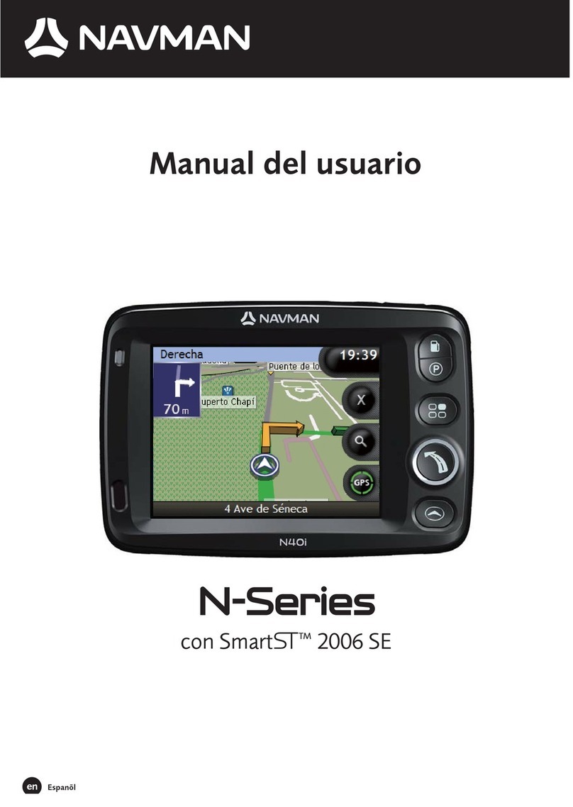
AlliedSignal Bendix/King KLN 89 Manual

Pilot’s Guide
ORS 01/02
KLN 89
KLN 89B
Bendix/King®
GPS Navigation System
A

KLN 89/89B Pilot’s Guide
006-08786-0000
for KLN 89 and KLN 89B
with
Operational Revision Status
ORS 01 and 02
IMPORTANT: Special installation procedures must be followed in
order for the KLN 89B to be certified for IFR En route, Terminal and
Non-precision Approach use. If these procedures are followed, the
KLN 89B can be used for IFR use. Consult the KLN 89B Flight
Manual Supplement for the operating limitations of this unit.
June 1996

IMPORTANT:
This Pilot’s Guide covers both the KLN 89 (VFR only) and KLN
89B (IFR approved for Enroute, Terminal, and Non-precision
Approach phases of flight). There are numerous places
throughout this guide which discuss features and operational
characteristics which specifically apply to KLN 89B, and not to
KLN 89. These parts of the Pilot’s Guide refer specifically to
KLN 89B, and often are marked with a double dagger symbol (‡).
Likewise, chapter 5, “Approaches and SID/STARs” applies only
to KLN 89B. For features that apply to both KLN 89 and KLN
89B, a generic reference to “KLN 89(B)” is used.
NOTE: A “whiskers” border is used around data
on some of the figures in this Pilot's Guide to
indicate that the data inside the border is
flashing.
WARNING: The KLN 89 and KLN 89B display GPS-derived alti-
tude on the OTH 1 page. Do not use the GPS-derived altitude for
navigation. Due to Selective Availability position degradation
and other factors, the GPS altitude is normally 300 feet or more
in error, which is unacceptable for vertical navigation.
åå.ånm| ZBV
åååååå|BIMINI
# Leg| N 25°
VOR 1 | W 79°

KLN89/KLN 89B Pilot’s Guide Table of Contents
TOC-1
INTRODUCTION .........................................................................i
KLN 89(B) SNEAK PREVIEW .......................................................ii
HOW-TO INDEX .......................................................................iv
1. KLN 89(B) SYSTEM COMPONENTS ....................................1-1
2. DATA BASE .....................................................................2-1
2.1. Data Basics ....................................................................2-1
2.2. Data Base Contents and Coverage Areas .....................2-1
2.3. ICAO Identifiers .............................................................2-4
2.4. Updating the Data Base .................................................2-4
2.4.1. Computer Updating of the Data Base ..................2-5
2.4.2 Card Exchange Updating of the Data Base .........2-8
2.5. User Defined Data Base ................................................2-8
2.6. Data Base Update Service Options ...............................2-9
3. BASIC GPS OPERATION ......................................................3-1
3.1. Coverage Area ...............................................................3-1
3.2. Turn-on and Self Test ....................................................3-1
3.3. Display Format ...............................................................3-8
3.4. Basic Operation of Panel Controls ...............................3-11
3.4.1. Page Selection ...................................................3-12
3.4.2. Data Entry ..........................................................3-13
3.4.3. The Duplicate Waypoint Page ............................3-15
3.4.4. Cyclic Fields .......................................................3-17
3.5. Message Page .............................................................3-17
3.6. Initialization and Time to First Fix ................................3-18
3.7. Selecting and Scanning Waypoints .............................3-21
3.7.1. Selecting Waypoints by Identifier .......................3-21
3.7.3. Selecting Waypoints by Scanning ......................3-23
3.7.4. Selecting Waypoints by Name or City ................3-24
3.8. “Nearest” Functions .....................................................3-26
3.8.1. Viewing the Nearest Waypoints .........................3-27
3.8.1.1. Nearest Airport Criteria..............................3-28
3.8.1.2. Continuous Display of Nearest Airport.......3-29
3.8.2. Viewing the Nearest Special Use Airspaces ......3-29
3.8.3. Viewing the Nearest Flight Service Station
Frequencies ....................................................3-31
3.8.4. Viewing the Nearest Center Frequencies ..........3-32

Table of Contents
TOC-2
3.9. Direct to Operation .......................................................3-32
3.9.1. Initiating a Direct To ...........................................3-33
3.9.2. Cancelling a Direct To ........................................3-35
3.9.3. Waypoint Alerting for Direct To Operation .........3-35
3.10. Navigation Pages .......................................................3-36
3.10.1. The Navigation 1 (NAV 1) Page .......................3-36
3.10.2. The Navigation 2 (NAV 2) Page .......................3-39
3.10.3. The Navigation 3 (NAV 3) Page .......................3-40
3.10.4. The Navigation 4 (NAV 4) Page .......................3-40
3.11. Waypoint Pages .........................................................3-45
3.11.1. Airport Pages ...................................................3-45
3.11.1.1. The Airport 1 (APT 1) Page.....................3-45
3.11.1.2. The Airport 2 (APT 2) Page.....................3-46
3.11.1.3. The Airport 3 (APT 3) Page.....................3-47
3.11.1.4. The Airport 4 (APT 4) Page.....................3-48
3.11.1.5. The Airport 5 (APT 5) Page.....................3-49
3.11.1.6. The Airport 6 (APT 6) Page.....................3-50
3.11.1.7. The Airport 7 (APT 7) Page.....................3-51
3.11.1.8. The Airport 8 (APT 8) Page.....................3-52
3.11.2. VOR Pages ......................................................3-53
3.11.2.1. The VOR 1 Page .....................................3-53
3.11.2.2. The VOR 2 Page .....................................3-53
3.11.3. NDB Pages ......................................................3-54
3.11.3.1. The NDB 1 Page......................................3-54
3.11.3.2. The NDB 2 Page......................................3-54
3.11.4. Intersection Pages ...........................................3-55
3.11.4.1. The Intersection 1 (INT 1) Page ..............3-55
3.11.4.2. The Intersection 2 (INT 2) Page ..............3-55
3.11.5. USER Waypoint Pages ...................................3-56
3.11.5.1. The User 0 (USR 0) Page........................3-56
3.11.5.2. The User 1 (USR 1) Page........................3-56
3.11.5.3. The User 2 (USR 2) Page........................3-56
3.11.5.4. The User 3 (USR 3) Page........................3-57
3.12. Altitude pages ............................................................3-58
3.13. Viewing and Setting the Date and Time ....................3-60
3.14. The Other (OTH) Pages ............................................3-62
3.14.1. Determining the Status of the GPS Signals .....3-62

3.14.2. Viewing and Deleting User Waypoints and
Waypoint Remarks ..........................................3-64
3.14.2.1. The OTH 4 Page......................................3-65
3.14.2.2. The OTH 5 Page......................................3-65
3.14.3. Viewing the KLN 89(B) Software Status
(the OTH 6 page) ............................................3-66
3.15. Remote Mounted Annunciators .................................3-66
3.16. Avionics Bus Voltage Alerting.....................................3-67
3.17. Special Use Airspace Alerting ...................................3-68
3.18. Sample Trip ..............................................................3-71
3.18.1 Pre-departure ..................................................3-71
3.18.2 Enroute ............................................................3-72
3.18.3 Terminal Area ..................................................3-73
4. ADVANCED GPS OPERATION .............................................4-1
4.1. Creating and Modifying Flight Plans ..............................4-1
4.1.1. Creating a Flight Plan ...........................................4-1
4.1.2. Viewing Distance and Desired Track Between
Stored Flight Plan Waypoints ............................4-4
4.1.3. Activating a Numbered Flight Plan .......................4-4
4.1.4. Adding a Waypoint to a Flight Plan ......................4-5
4.1.5. Deleting a Waypoint from a Flight Plan ................4-6
4.1.6. Deleting Flight Plans ............................................4-7
4.1.7. Storing FPL 0 as a Numbered Flight Plan ............4-7
4.2. Operating from the Active Flight Plan ............................4-8
4.2.1. General Procedures .............................................4-8
4.2.2. Turn Anticipation and Waypoint Alerting ..............4-9
4.2.3. Viewing the Waypoint Pages for the Active
Flight Plan Waypoints .....................................4-11
4.2.4. Combining Direct To and Flight Plan Operation .4-11
4.2.5. Viewing Distance, ETE, ETA, or Desired Track
to Flight Plan Waypoints .................................4-13
4.3. Altitude Alerting ............................................................4-14
4.4. Advisory VNAV Operation ...........................................4-17
4.4.1. VNAV for Direct To Operation ............................4-17
4.4.2. VNAV for Flight Plan Operation .........................4-20
4.4.3. VNAV from NAV 1 Page ....................................4-20
4.5. Calculator Pages .........................................................4-21
4.5.1. The Calculator 1 (CAL 1) Page ..........................4-21
KLN89/KLN 89B Pilot’s Guide Table of Contents
TOC-3

4.5.2. The Calculator 2 (CAL 2) Page ..........................4-23
4.5.3. The Calculator 3 (CAL 3) Page ..........................4-25
4.5.4. The Calculator 4 (CAL 4) Page ..........................4-26
4.5.3. The Calculator 5 (CAL 5) Page ..........................4-27
4.5.6. The Calculator 6 (CAL 6) Page ..........................4-27
4.5.7. The Calculator 7 (CAL 7) Page ..........................4-28
4.5.8. The Calculator 8 (CAL 8) Page...........................4-29
4.6. Creating User-defined Waypoints ...............................4-30
4.6.1. Creating a Waypoint at Your Present Position ...4-31
4.6.2. Creating a Waypoint at a Certain Latitude/
Longitude ........................................................4-32
4.6.3. Creating a Waypoint Referenced from Another
Waypoint .........................................................4-33
4.7. Navigation Modes ........................................................4-35
4.7.1. Selecting the Leg Mode or the OBS mode .........4-35
4.7.2. The Leg Mode ....................................................4-35
4.7.3. The OBS Mode ..................................................4-36
4.7.4. Switching From the Leg Mode to the OBS Mode 4-38
4.7.5. Effects of Switching From OBS Mode to
Leg Mode ........................................................4-38
4.7.6. Going Direct to a Waypoint While in the
OBS Mode .......................................................4-39
4.7.7. Activating a Waypoint While in the OBS Mode ..4-39
4.7.8. Changing the CDI scale factor ...........................4-40
4.8. The Fuel Management Pages .....................................4-41
4.8.1. The Other 7 (OTH 7) page .................................4-42
4.8.2. The Other 8 (OTH 8) page .................................4-43
4.8.3. The Other 9 (OTH 9) page .................................4-44
4.8.4. The Other 10 (OTH 10) page .............................4-44
4.9. The Air Data Pages .....................................................4-44
4.9.1. The Other 11 (OTH 11) page .............................4-45
4.9.2. The Other 12 (OTH 12) page .............................4-46
4.10. Magnetic Variation .....................................................4-46
4.11. Using the Take-home Mode ......................................4-48
5. APPROACHES AND SID/STARS (KLN 89B ONLY) ...........5-1
5.1. Non-Precision Approach Operations ............................5-1
5.1.1. Selecting An Approach .........................................5-5
5.1.2. Interpreting What You See ...................................5-7
Table of Contents
TOC-4

5.1.3. Changing Or Deleting An Approach Once
Loaded Into The Flight Plan ..............................5-9
5.1.4. Example Approach: No Procedure Turn ...........5-10
5.1.5. Example Approach: Off-Airport Navaid .............5-14
5.1.6. Example Approach: Radar Vectors ...................5-18
5.1.7. Example Approach: On-Airport Navaid .............5-19
5.1.8. Example Approach: DME Arc ...........................5-22
5.1.9. Approach Problems ...........................................5-27
5.2 SID/STAR Procedures .................................................5-29
5.2.1. Selecting A SID ..................................................5-30
5.2.2. Selecting A STAR ..............................................5-31
5.2.3. Editing a SID or STAR .......................................5-32
5.2.4. Example of a SID Procedure ..............................5-34
5.2.5. Example of a STAR Procedure ..........................5-36
APPENDIX A - NAVIGATION TERMS ......................................A-1
APPENDIX B - MESSAGE PAGE MESSAGES ........................B-1
APPENDIX C - SCRATCHPAD MESSAGES ............................C-1
APPENDIX D - ABBREVIATIONS .............................................D-1
STATE ABBREVIATIONS ....................................................D-1
CANADIAN PROVINCE ABBREVIATIONS .........................D-2
COUNTRY ABBREVIATIONS .............................................D-2
ARTCC ABBREVIATIONS ...................................................D-8
OTHER ABBREVIATIONS USED ON KLN 89 PAGES .... D-17
APPENDIX E - LAT/LON CONVERSIONS ................................E-1
APPENDIX F - GPS PRIMER .....................................................F-1
KLN89/KLN 89B Pilot’s Guide Table of Contents
TOC-5

Table of Contents
TOC-6
This page intentionally left blank

KLN 89/KLN 89B Pilot’s Guide Introduction
i
INTRODUCTION
Congratulations for choosing the Bendix/King KLN 89 or KLN 89B
GPS! Celestial navigation will now be a way of life for you. The phe-
nomenal accuracy of GPS, along with the KLN 89(B)’s user-friendly
operation and graphics display will make flying a delight. Not only will
the KLN 89(B) help you to navigate more easily and more accurately,
its trip planning features, air data calculations, and other useful fea-
tures will make you feel like you’re flying with a true flight
management system.
In addition, KLN 89B may be IFR approved for En route, Terminal,
and Non-precision Approach operations. We think you’ll find that
having an abundance of navigational data (not to mention a moving
map!) available to you will make non-precision approaches more pre-
cise and more enjoyable.
This Pilot's Guide will be of great help to you. It is written in plain,
simple English and it assumes you are not an experienced user of
GPS or other type of long range navigation equipment. If you are
experienced, so much the better. This Pilot's Guide also includes
hundreds of sample screen figures and other illustrations to make
your learning easier. It is designed so that you can start at the front
and progress in the order presented; however, you may want to skip
around and learn things in your own order. Also, on page iv, there is
an index of frequently used procedures which will help you find the
page that describes how to do exactly what you want to do. There
are also several appendices in the back of the manual that you may
find useful from time to time.
Be sure to keep this Pilot's Guide handy with you in the airplane. It is
designed to fit easily in the glove box, or in the seat pocket. The KLN
89(B) is very simple to operate, but the Pilot's Guide can sure be of
help to you.
One last thing. Don't get so involved in learning to use the KLN 89(B)
that you forget to fly the airplane. Be careful, and remember to keep a
close eye out for other aircraft.

KLN 89(B) SNEAK PREVIEW
If you absolutely can’t wait to use your KLN 89(B) until you’ve read
this Pilot’s Guide, this section is for you. This page will teach you just
enough to get going and then learn by doing. This operational pre-
view assumes the KLN 89(B) has been properly installed, the unit
was previously operational in the same general geographical loca-
tion, and that no peripheral equipment interfaced with the KLN 89(B)
(such as external HSIs, CDIs, autopilots, moving map display, etc.) is
to be used at this time. If you are using this operational preview in
flight, do so only in good VFR conditions and only with an alternate
means of navigation (including pilotage) available to cross-check
position.
1.Turn the unit on with the On/Off knob (the small knob in lower left
hand corner).
2.For a few seconds, the Power On Page is displayed while the
unit runs a self-test. Afterwards, the Self-test Page is displayed.
If the KLN 89(B) is receiving an altitude from an encoding altime-
ter, the present indicated altitude will be displayed on line 2. The
bottom line should display Passand a flashing Ok?. Press the
Fbutton to approve the Self-test Page.
3.The Initialization Page will now be displayed. If the date and time
are incorrect by more than 10 minutes, refer to section 3.2 of this
Pilot’s Guide. The right side of the screen should show the identi-
fier of the nearest airport to the initial position, along with a radial
and distance from that airport waypoint. Press Fwith the cur-
sor flashing over Ok?to approve the Initialization Page.
4.If you are using a KLN 89, or your KLN 89B has been configured
for VFR use only, the VFR page will now be displayed to notify
you of the VFR limitation. Press Fto approve this page.
5.The Data Base Page is now displayed showing the date the data
base expires or the date it expired. Press Fto acknowledge
the information displayed on this page.
Introduction
ii

KLN 89/KLN 89B Pilot’s Guide Introduction
iii
6. The next page displayed will probably be a page showing the
VHF communication frequencies for the airport you are at. For
now, use the right outer knob to turn to the NAV page type
(watch the lower left corner of the screen and the small bar at the
bottom to know when you are there). Then use the right inner
knob to select the NAV 2 page if not already there. The NAV 2
page shows your present position relative to a nearby VOR.
Verify that this position is correct before proceeding.
7. Press the Dbutton. A page with the words DIRECT TO is now
displayed on the screen.
In step 8 you will enter the ICAO identifier of the airport. The identifi-
er will have a “K” prefix for a Continental U.S. airport, a “C” prefix for
a Canadian airport, or a “P” prefix (in some cases) for an Alaskan air-
port if the identifier is all letters. For example, LAX becomes KLAX.
For these countries if the identifier contains any numbers, there is no
prefix. For example, TX04 is entered TX04. For other areas of the
world the airport identifier should be entered identically to how it is
charted.
8. Rotate the right inner knob until the first character of the airport
identifier is displayed. Turn the right outer knob one step clock-
wise to move the flashing segment to the second character
position. Rotate the right inner knob to select the second charac-
ter of the identifier. Use this procedure to enter the complete
airport identifier.
9. Press F. The display will change to a page showing the identi-
fier, name, city, and state/country of the airport just entered.
Confirm that the correct airport is displayed. Press Fa second
time to approve the airport data.
10. A Navigation page (specifically the NAV 1 page) is now on the
screen. It displays the desired ground track, actual ground track,
bearing, and ETE to the destination airport. In addition, it displays
a course deviation indicator (CDI).
See—wasn’t that easy?

Introduction
iv
HOW-TO INDEX
This index will help you quickly find important procedures at a glance.
The list is alphabetized by action words.
TO: SEE PAGE:
Activate a waypoint in OBS mode without changing the
selected course...............................................................................4-40
Activate one of the previously created numbered flight plans..........4-4
Add a waypoint to a flight plan..........................................................4-5
‡Add an individual waypoint in the SID or STAR procedure..........5-33
Adjust the minimum display brightness ............................................3-9
Calculate distance, time, and ESA for a flight plan........................4-23
Calculate distance, bearing, and time from waypoint to waypoint.4-22
Calculate fuel requirements for a flight plan ...................................4-25
Calculate fuel requirements from waypoint to waypoint.................4-23
Calculate sunrise/sunset times.......................................................4-29
Calculate the density altitude..........................................................4-27
Calculate the pressure altitude .......................................................4-26
Calculate the true airspeed (TAS) ..................................................4-27
Calculate the winds aloft.................................................................4-28
Cancel Direct To operation.............................................................3-35
Change a cyclic field.......................................................................3-17
Change course modes....................................................................4-35
‡Change or delete an entire SID or STAR procedure from
the active flight plan ........................................................................5-33
Change the baro setting..................................................................3-58
Change the CDI scale factor...........................................................4-40
Change the default first waypoint character...................................3-15
Change the NAV 2 page present position reference waypoint......3-39
Change the present fuel on board..................................................4-43
Change the selected course in OBS mode....................................4-37

KLN 89/KLN 89B Pilot’s Guide Introduction
v
TO: SEE PAGE:
Create a flight plan............................................................................4-2
Create a user-defined waypoint at your present position...............4-31
Create a user-defined waypoint using the radial/distance method4-33
Create a user-defined waypoint with latitude/longitude..................4-32
Cycle between distance and desired track display on a
numbered flight plan page ................................................................4-4
Cycle between distance, ETE, ETA, and desired track on the
FPL 0 page......................................................................................4-13
Delete a flight plan which is no longer required................................4-7
Delete a user-defined waypoint from the OTH 4 page...................3-65
Delete a waypoint from a flight plan..................................................4-6
Delete a waypoint remark from the OTH 5 page............................3-66
‡Delete an individual waypoint in a SID or STAR procedure.........5-33
Display the nearest airport continuously.........................................3-29
Enable the voltage alert feature......................................................3-67
Enter a user-defined waypoint remark on the USR 3 page............3-57
Enter a waypoint identifier...............................................................3-13
Enter an airport remark on the APT 6 page....................................3-51
Enter the local magnetic variation manually on the SET 2 page ...4-47
Fly direct to a waypoint ...................................................................3-33
Fly direct to a waypoint in the active flight plan (FPL 0).................4-12
Initialize the position from the SET 1 page.....................................3-19
‡Perform a manual RAIM calculation.............................................5-28
Recenter the D-Bar by going direct to the active waypoint............3-35
‡Replace an existing approach, or delete an approach...................5-9
‡Select a SID ..................................................................................5-30
‡Select a STAR...............................................................................5-31
Select a VOR or NDB by navaid name...........................................3-24
Select a waypoint by identifier from a waypoint page ....................3-21

TO: SEE PAGE:
Select a waypoint by scanning with the cursor off..........................3-23
Select a waypoint by scanning with the cursor on..........................3-23
Select an airport by scanning the airport name..............................3-25
‡Select and load an approach into the active flight plan (FPL 0).....5-5
Set the alarm...................................................................................4-26
Set the date on the SET 2 page .....................................................3-60
Set the time on the SET 2 page......................................................3-61
Specify the nearest airport criteria..................................................3-28
Store the active flight plan as a numbered flight plan.......................4-7
Turn on and initialize the KLN 89(B).................................................3-2
Update the KLN 89(B) data base by computer ................................2-6
Use altitude alerting ........................................................................4-14
Use the NAV 1 page to view the VNAV status...............................4-20
Use VNAV on a Direct To...............................................................4-17
View a message..............................................................................3-18
View the waypoints in the flight plan that are not the
active waypoint................................................................................4-11
Introduction
vi

KLN 89/KLN 89B Pilot’s Guide Introduction
vii
This page intentionally left blank

System Components
System Components
Chapter 1
1-0
N
S
E
W
TO
FR
33
30
24
21
15
12
6
3
OBS
GS
N
A
V
ı
GS
ı
N
33
30
W
24
21
S
15
12
E
6
3
HDGNAV
GS
AIRCRAFT
POWER
ALTITUDE
11-33V
GRAY CODE
WPT ALERT
MESSAGE
MOVING MAP
DISPLAYS
KA 92 GPS ANTENNA
HSI CDI
AUTOPILOT
REMOTE
ANNUNCIATORS
RS-232
OUTPUT
KLN 89(B) SYSTEM
REQUIRED FOR ALL INSTALLATIONS
OPTIONAL
OR
KI 525A KI 206
COMPATIBLE
FUEL
MANAGEMENT
SYSTEM
REQUIRED FOR IFR APPROACH INSTALLATIONS (OF KLN 89B)
RS-232
INPUT
RS-232
INPUT
HEADING
RS-232
INPUT GPS
APR
REMOTE SWITCH/
ANNUNCIATOR
ı
N
S
E
W
33
30
24
21
15
12
6
3
A
D
F
KI 229
N
33
30
W
24
21
S
15
12
E
6
3
A
D
F
A
D
F
NAV NAV
KNI 582
OR
COMPATIBLE
AIR
DATA
COMPUTER
LEFT/RIGHT
D-BAR
SELECTED
COURSE
GPS
ON
OFF
APT VOR NDB INT USR ACT NAV FPL CAL SET OTH
GKLN 89 TSO
CRSR
PULL SCAN
ëî.ïnm|∞VOR 25R KLAX
ELMOOi|≥ 3 ELMOOi 15
>Leg| 4 LAX18 22
FPL 0 | 9:KLAX 66
ENT
>CLRD
OBSNRSTALTMSG
RMI
ALT HDG NAV APR APGS
ALT HDG NAV APR BC AP
ENG
TEST
KC 193
YD
RN RC PC
BC
ı
DN
UP

KLN 89/KLN 89B Pilot’s Guide System Components
1-1
System Components
Chapter 1
1. KLN 89(B) SYSTEM COMPONENTS
A basic KLN 89(B) system consists of a panel mounted KLN 89(B)
GPS and a KA 92 GPS antenna. An altitude input is required to
obtain full navigation and operational capabilities. Additional system
components may be added or interfaced to the KLN 89(B) which
increase its features and capabilities. Some of these optional compo-
nents include an external course deviation indicator (CDI) or
horizontal situation indicator (HSI), autopilot, and external annuncia-
tors. Typically, an altitude input, an external indicator, and external
annunciators are required for IFR approach certification.
The KLN 89(B) panel mounted unit contains the GPS sensor, the
navigation computer, a Gas Plasma Discharge Display, and all con-
trols required to operate the unit. It also includes the data base card
which slides into the left side of the front panel.
The KA 92 GPS “patch” antenna is available for use with the KLN
89(B). It is designed to always be mounted on the top of the aircraft.
The KLN 89(B) has analog outputs to drive the left-right deviation bar
of most mechanical CDIs and HSIs. In addition, the NAV mode of the
Bendix/King KFC 150, KAP 150, KAP 150H, KAP 100, KFC 200,
KAP 200, KFC 250, KFC 275, KFC 300, and KFC 325 flight control
systems may be coupled to the KLN 89(B). Many other autopilots
may also be coupled to the KLN 89(B). Actual autopilot performance
and capability when coupled to the KLN 89(B) may vary significantly
from one autopilot model to another.
Altitude may be provided to the KLN 89(B) from an encoding altime-
ter or blind encoder. Altitude is used as an aid in position
determination when not enough satellites are in view.
All IFR installations require remote annunciators to be mounted in the
aircraft panel in order to select and indicate the status of certain
KLN 89(B) functions. En route and terminal IFR certifications require
annunciators for message (MSG) and waypoint alert (WPT). Non-
precision approach certifications also require a switch/annunciator to
select and display when the approach mode is armed or active.

Each KLN 89(B) system includes a configuration module which is
attached to the KLN 89(B) mounting rack. The module allows the
KLN 89(B) to be configured for the unique characteristics of your
equipment installation. Parameters that are set by the configuration
module include:
•‡Whether the KLN 89B may be used for IFR operations or not,
and if it may be used for non-precision approach IFR
operations. KLN 89 may only be used for VFR navigation.
•Whether or not the altitude alert function in enabled. See
section 4.3.
•Whether or not an external fuel management system is
interfaced to the KLN 89(B). See section 4.8.
•Whether or not an external air data computer is interfaced to
the KLN 89(B). See section 4.9.
•The conditions for the aircraft bus voltage alert to activate. See
section 3.16.
The configuration information is stored both in the module and in the
KLN 89(B) internal memory. If the KLN 89(B) detects a difference
between the configuration stored in the module and the configuration
stored in the internal memory (which should only occur following the
exchange of KLN 89 or KLN 89B units), the configuration information
will automatically be updated to the configuration specified in the
configuration module.
If an error is detected in the configuration data, a warning page
stating Configuration Mem Errorwill be displayed during the
KLN 89(B) start-up sequence, and the configuration memory will be
set to arbitrary default values. See an authorized AlliedSignal
Service center to correct the configuration memory error.
System Components
1-2
System Components
Chapter 1

KLN 89/KLN 89B Pilot’s Guide System Components
1-3
System Components
Chapter 1
This page intentionally left blank
This manual suits for next models
1
Table of contents


