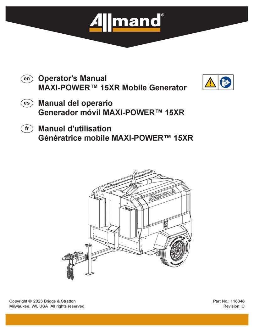
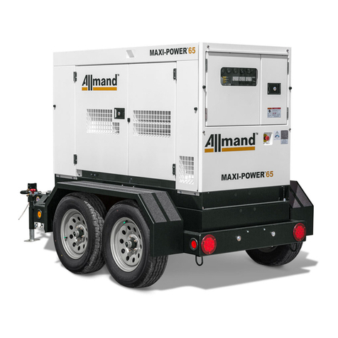
Allmand MAXI-POWER 25 User manual

Operator’s Manual
MAXI-POWER™ 25 Mobile Generator
Copyright © 2022 Briggs & Stratton
Milwaukee, WI, USA All rights reserved. Part No.: 122092
Revision: A
en
Manuel d'utilisation
Génératrice mobile MAXI-POWER™ 25
Manual del operario
Generador móvil MAXI-POWER™ 25
fr
es
Not For Reproduction

www.allmand.com2
Breathing diesel engine exhaust exposes you
to chemicals known to the State of California
to cause cancer and birth defects or other
reproductive harm.
• Always start and operate the engine in a well-
ventilated area.
• If in an enclosed area, vent the exhaust to the
outside.
• Do not modify or tamper with the exhaust
system.
• Do not idle the engine except as necessary.
For more information go to
www.P65Warnings.ca.gov/diesel.
Recording the equipment information will help when placing
an order for replacement parts and/or decals.
Manual Contents:
Record Important Information
Introduction ....................................................................... 2
Products Covered by This Manual ................................... 2
Safety ................................................................................. 2
Features and Controls ...................................................... 7
Preparing the Generator Trailer for Use ...................... 9
Transporting the Generator Trailer ........................... 10
Operation ........................................................................ 14
Maintenance ................................................................... 20
Specications ................................................................ 25
Troubleshooting ............................................................ 26
Reporting Safety Defects ............................................ 27
Tire Safety Information ................................................ 27
Addendum - Unit Options .......................................... 34
Company Equipment No:
Unit Model No:
Unit VIN:
Engine Model No: Serial No:
Generator Model No: Serial No:
Accessories:
WARNING
Introduction
About This Manual
TAKE TIME TO READ THIS MANUAL THOROUGHLY
This instruction manual provides necessary instructions for
the Allmand® Maxi-Power™ 25 mobile generator.
The information found in this manual is in eect at the time
of printing. Briggs & Stratton may change contents without
notice and without incurring obligation.
The images throughout this manual are representative, and
may dier from your model.
Any reference in this manual to left or right shall be
determined by looking at the trailer from the rear.
If uncertain about any of the information in the manual,
contact the Allmand service department at
1-800-562-1373, or contact us through the Allmand website,
www.allmand.com.
Save these original instructions for future reference.
Products Covered by This
Manual
The following products are covered by this manual:
Maxi-Power™ 25
Safety
For your safety, the safety of others, and to protect the
performance of equipment, follow the precautions listed
throughout the manual before operation, during operation
and during periodic maintenance procedures.
Indicates a potential personal injury hazard.
DANGER
Indicates a hazardous situation which, if not avoided, will
result in death or serious injury.
WARNING
Indicates a hazardous situation which, if not avoided, could
result in death or serious injury.
CAUTION
Indicates a hazardous situation which, if not avoided, could
result in minor or moderate injury.
Safety Denitions
NOTICE
Information considered important but not hazard related.
Not For Reproduction

en
English 3
The following section contains general safety precautions
and guidelines that must be obeyed to reduce risk to
personal safety. Special safety precautions are listed in
specic procedures. Read and understand all of the safety
precautions before operating or performing repairs or
maintenance.
Safety Precautions
DANGER
Electrocution Hazard
• High voltage is present when engine is running.
Never attempt to service electrical components while
engine is running.
• Do not operate the unit if the insulation on the
electrical cord or other electrical wiring is cut or
worn or if bare wires are exposed. Repair or replace
damaged wiring before starting the engine.
WARNING
Unsafe Operation Hazard
• Never permit anyone to install or operate the
equipment without proper training.
• Read and understand this Operator’s Manual, the
Engine Operator’s Manual, and any other component
manuals before operating or servicing the light tower
to make sure that safe operating practices and
maintenance procedures are followed.
• Safety signs and decals are additional reminders for
safe operating and maintenance techniques.
WARNING
Fall Hazard
• Never carry riders on the equipment.
WARNING
Modication Hazard
• Never modify the equipment without written consent
of the manufacturer. Any modication could aect the
safe operation of the equipment.
WARNING
Exposure Hazard
• Always wear personal protective equipment, including
appropriate clothing, gloves, work shoes, and eye
and hearing protection, as required by the task at
hand.
WARNING
Fire and Explosion Hazard
Batteries give o explosive gases during recharging.
Sparks could cause explosions, resulting in death or
serious injury.
WARNING
Burn Hazard
Batteries contain acid, which is extremely caustic. Con-
tact with battery contents could cause severe chemical
burns.
WARNING
Shock Hazard
Batteries present a risk of electric shock and high short
circuit current.
• Always disconnect the negative (-) battery cable be-
fore servicing equipment.
• DO NOT dispose of battery in a re. Recycle battery.
• DO NOT allow any open ame, spark, heat, or lit cig-
arette during and for several minutes after charging a
battery.
• DO NOT open or mutilate battery.
• DO NOT charge a frozen battery. Always slowly warm
the battery to room temperature before charging.
• Wear protective gloves, rubber apron, rubber boots
and rubber gloves.
• Remove watches, rings, or other metal objects.
• Use tools having insulated handles.
WARNING
Carbon Monoxide Hazard
Engine exhaust contains carbon monoxide, a poisonous
gas that could kill you in minutes. You cannot smell it, see
it, or taste it. Even if you do not smell exhaust fumes, you
could still be exposed to carbon monoxide gas.
• Operate this product ONLY outdoors in an area that
will not accumulate deadly exhaust gas.
• Direct exhaust gas away from any windows, doors,
ventilation intakes, sot vents, crawl spaces, open
garage doors or other openings that can allow
exhaust gas to enter inside or be drawn into a
potentially occupied building or structure.
Not For Reproduction

www.allmand.com4
• Carbon monoxide detector(s) MUST be installed and
maintained indoors according to the manufacturer’s
instructions/recommendations. Smoke alarms cannot
detect carbon monoxide gas.
• If you start to feel sick, dizzy, weak, or your carbon
monoxide alarm sounds while using this product, get
to fresh air right away. Call emergency services. You
may have carbon monoxide poisoning.
WARNING
Fire and Explosion Hazard
• Diesel fuel is ammable and explosive under certain
conditions.
• Never use a shop rag to catch fuel.
• Wipe up all spills immediately.
• Never refuel with the engine running.
• Store any containers containing fuel in a well
ventilated area, away from any combustibles or
sources of ignition.
WARNING
Alcohol and Drug Hazard
• Never operate the light tower while under the
inuence of alcohol or drugs, or when ill.
WARNING
Entanglement / Sever Hazard
• Always stop the engine before beginning service.
• If the engine must be serviced while it is operating,
remove all jewelry, tie back long hair and keep hands,
other body parts and clothing away from moving/
rotating parts.
• Verify that all guards and covers are attached
properly to the equipment before starting the engine.
Do not start the engine if any guards or covers are
not properly installed on the equipment.
• Attach a “Do Not Operate” tag near the key switch
while performing maintenance on the equipment.
WARNING
Flying Object Hazard
• Always wear eye protection when cleaning the
equipment with compressed air or high pressure
water. Dust, ying debris, compressed air,
pressurized water or steam may injure your eyes.
WARNING
Coolant Hazard
• Wear eye protection and rubber gloves when
handling engine coolant. If contact with the eyes or
skin should occur, ush eyes and wash immediately
with clean water.
WARNING
Burn Hazard
• Opening cap on hot radiator could result in death
or serious injury. Allow radiator to cool down before
opening cap.
WARNING
Burn Hazard
• Keep hands and other body parts away from hot
surfaces.
• Handle hot components, such as light xtures, with
heat resistant gloves.
NOTICE
• Any part which is found defective as a result of
inspection or any part whose measured value does
not satisfy the standard or limit MUST be replaced.
• Always tighten components to the specied torque.
Loose parts can cause equipment damage or cause it
to operate improperly.
• Follow the guidelines of the Environmental Protection
Agency (EPA), Environment Canada (EC) or other
governmental agencies for the proper disposal of
hazardous materials such as engine oil, diesel fuel
and engine coolant.
• Only use replacement parts specied. Other
replacement parts may eect warranty coverage.
• Clean all accumulated dirt and debris away from the
body of the equipment and its components before
you inspect the equipment or perform preventative
maintenance procedures or repairs. Operating
equipment with accumulated dirt and debris will
cause premature wear of equipment components.
• Never dispose of hazardous materials by dumping
them into a sewer, on the ground, or into groundwater
or waterways.
• Retrieve any tools or parts that may have dropped
inside of the equipment to avoid improper equipment
operation.
• If any alert indicator illuminates during equipment
operation, stop the engine immediately. Determine
the cause and repair the problem before continuing to
operate the equipment.
Not For Reproduction

en
English 5
It is a violation of California Public Resource Code,
Section 4442, to use or operate the engine on any forest-
covered, brush-covered, or grass-covered land unless
the exhaust system is equipped with a spark arrester, as
dened in section 4442, maintained in eective working
order. Other states or federal jurisdictions may have
similar laws; reference Federal Regulation 36 CFR Part
261.52.
Safety Decals
Before operating your unit, read and understand the
following safety decals. The cautions, warnings, and
instructions are for your safety. To avoid personal injury or
damage to the unit, understand and obey all the decals.
Keep the decals from becoming dirty or torn, and replace
them if they are lost or damaged. Also, if a part needs to
be replaced that has a decal attached to it, make sure to
order the new part and decal at the same time.
If any safety or instructional decals become worn or
damaged, and cannot be read, order replacement decals
from your dealer.
All Models
DANGER - Entering electrical
compartment while equipment is
in operation will result in death or
serious injury. Unplug equipment
before entering electrical
compartment.
Part No. 118074
118074
DANGER - Entering electrical
compartment while equipment is
in operation will result in death or
serious injury. Unplug equipment
before entering electrical
compartment.
Part No. 118104
118104
DANGER
Entering electrical compartment while
equipment is in operation will result in death
or serious injury.
DANGER
Shut down equipment before entering
electrical compartment.
Le fait d’entrer dans le compartiment
électrique tandis que l’équipement est utilisé
causera la mort ou des blessures graves.
Éteindre l’équipement avant d’entrer dans le
compartiment électrique.
Machine Grounding Information
Part No. 110362
NOTICE
AVIS
Neutral bonded to frame.
Machine to be grounded in accordance
with requirements as outlined by local
inspection authorities.
Neutre mis à al masse à la carcasse du
moteur.
L'apparel doit etre misa la terre
conformement aux exgences des
services d'inspection locaux.
110362
WARNING - Contact with rotating
parts could result in death or
serious injury. Keep away from
rotating parts.
Part No. 118652 Contact with rotating parts could result in
death or serious injury. Keep away from
rotating parts.
Se tenir à l’écart des
pièces en mouvement.
Le contact avec des pièces en mouvement
pourrait résulter en de graves blessures voire
la mort.
118652
All Models
WARNING - Opening cap on hot
radiator could result in death or
serious injury. Allow radiator to
cool down before opening cap.
Part No. 118651
Opening cap on hot radiator
could result in death or
serious injury.
Allow radiator to cool down
before opening cap.
L’ouverture du bouchon sur
un radiateur chaud pourrait
causer la mort ou des
blessures graves.
Laisser le radiateur refroidir
avant de dévisser le
bouchon.
118651
WARNING - Contact with hot
exhaust gases and parts could
cause death or serious injury.
Avoid hot exhaust gases. Keep
hands and combustible materials
away from hot parts.
Part No. 118162
118162
WARNING - Contact with hot
exhaust gases and parts could
cause death or serious injury.
Avoid hot exhaust gases. Keep
hands and combustible materials
away from hot parts.
WARNING - Unexpected start of
engine could result in death or
serious injury. Read and follow
electronic controller operator’s
manual before operating or
servicing this equipment.
Part No. 122075
122075
AUTO
Le démarrage inattendu du moteur
pourrait provoquer la mort ou des
blessures graves.
Lire et suivre le manuel d’utilisation
du contrôleur électronique avant
d’utiliser ou de réparer cet
équipement.
Unexpected start of engine could
result in death or serious injury.
Read and follow electronic controller
operator’s manual before operating or
servicing this equipment.
WARNING - Smoking materials,
open ames, or other forms of
ignition near the battery could
cause explosion resulting in death
or serious injury. Keep smoking
materials, open ames, or other
forms of ignition away from the
battery.
WARNING - Exposure to corrosive
materials could cause result in
death or serious injury. Wear
protective gloves when handling
battery.
Part No. 122076
122076
Smoking materials, open flames, or
other forms of ignition near the
battery could cause explosion
resulting in death or serious injury.
Keep smoking materials, open
flames, and other forms of ignition
away from the battery.
Tenir les articles de fumeur, les
flammes nues ou les autres formes
d’allumage à l’écart de la batterie.
Les articles de fumeur, les flammes
nues ou d’autres formes d’allumage
près de la batterie pourraient causer
une explosion, causant la mort ou
des blessures graves.
Porter des gants de protection en
manipulant la batterie.
Toute exposition à des produits
corrosifs pourrait causer la mort ou
des blessures graves.
Wear protective gloves when
handling battery.
Exposure to corrosive material could
result in death or serious injury.
Not For Reproduction

www.allmand.com6
All Models
DANGER - Turning the voltage
switch to another position while
the unit is in operation could cause
an electric shock hazard from
the generator which will result
in death or serious injury. Turn
o the unit before turning the
voltage switch to another position.
A lock must be installed on the
switch to prevent the switch from
being turned while the unit is in
operation.
Part No. 122086
Turning the voltage switch to another
position while the unit is in operation
could cause an electric shock hazard
from the generator which will result in
death or serious injury.
Turn off the unit before turning the
voltage switch to another position. A
lock must be installed on the switch to
prevent the switch from being turned
while the unit is in operation.
Éteindre l’appareil avant de tourner
l’interrupteur de tension à une autre
position. Un cadenas doit être posé sur
l’interrupteur pour empêcher qu’il puisse
être tourné pendant que l’appareil est en
marche.
Tourner l’interrupteur de tension à une
autre position pendant que l’appareil est
en marche pourrait présenter un risque
de choc électrique de la génératrice
pouvant entraîner la mort ou de graves
blessures corporelles.
122086
Electronic Controller Instructions
Part No. 122080 1. Check engine oil and coolant levels. Refill as
needed.
2. Check fuel tank (and, if equipped, DEF tank)
levels. Refil as needed.
3. Drain water from fuel-water separator.
4. Set the voltage selector switch to the correct
voltage and phase position that is required
for operation.
OPERATION CHECKLIST
1. Vérifier les niveaux d’huile moteur et liquide
de refroidissement. Remplir si nécessaire.
2. Vérifier les niveaux du réservoir de carburant
et du réservoir DEF, si équipé. Remplir si
nécessaire.
3. Vidanger l’eau du séparateur carburant-eau.
4. Régler l’interrupteur du sélecteur de tension
à la bonne tension et position de phase
requises pour le fonctionnement.
LISTE DE VÉRIFICATION DE
FONCTIONNEMENT
MANUAL MODE START
1. Set all the circuit breakers (main and outlet)
to the OFF/0 position.
2. Set the electronic controller power switch to
the ON/1 position.
3. Press the manual mode button .
4. Press the start button to start the engine
run cycle. The engine will cycle through the
stages of preheat, engine start, engine
warming, and engine run. Allow the engine to
run for approximately 5 minutes.
5. Adjust the voltage as needed by using the
voltage adjustment control knob.
6. Set all the circuit breakers (main and outlet)
to the ON/1 position.
MANUAL MODE STOP
1. Set all the circuit breakers (main and outlet)
to the OFF/0 position.
2. Press the stop button to shutdown the
engine.
3. Set the electronic controller power switch to
the OFF/0 position.
MANUAL MODE OPERATION FONCTIONNEMENT EN MODE
MANUEL
* Refer to the operator’s manual for
instruction.
AUTO MODE OPERATION FONCTIONNEMENT EN MODE
AUTOMATIQUE
* Reportez-vous au manuel d’utilisation
pour plus d’informations.
122080
DÉMARRAGE EN MODE MANUEL
1. Régler tous les disjoncteurs (principal et
prises) à la position ARRÊT/0.
2. Régler l’interrupteur d’alimentation de la
commande électronique à la position
MARCHE/1.
3. Appuyer sur le bouton du mode manuel .
4. Appuyer sur le bouton de démarrage pour
démarrer un cycle du moteur. Le moteur fera
un cycle des étages de préchauffage,
démarrage du moteur, réchauffement du
moteur et fonctionnement du moteur. Laisser
le moteur tourner pendant environ 5 minutes.
5. Régler la tension au besoin en utilisant le
bouton de contrôle pour le réglage de la
tension.
6. Régler tous les disjoncteurs (principal et
prises) à la position MARCHE/1.
ARRÊT DU MODE MANUEL
1. Régler tous les disjoncteurs (principal et
prises) à la position ARRÊT/0.
2. Appuyer sur le bouton d’arrêt pour
arrêter le moteur.
3. Régler l’interrupteur d’alimentation de la
commande électronique à la position
ARRÊT/0.
Power Cable Routing Information
Part No. 110362
NOTICE
Route power cables under panel door to power
distribution terminals and single phase outlets.
122081
AVIS
Acheminer les câbles d’alimentation sous la
porte à panneau jusqu’aux bornes de distribution
de courant et aux prises monophasées.
Electrical Information
Part No. 122083
115°F/46°C
Hz/RPM
VL-N/VL-L
A
kW/kVA
Φ
INS.C
L
ASS
PF
F
277/480
30 MAX
20.0/25.0
3
0.8
MAX AMB
60/1800
115°F/46°C
F
120/208
69 MAX
20.0/25.0
3
0.8
60/1800
115°F/46°C
F
120/240
60 MAX
14.4/14.4
1
1.0
60/1800
122083
Φ
Φ Φ
Φ
Φ Φ
Φ
Φ Φ
WARNING - Switching the remote
fuel valve lever to another position
while the unit is running could
cause a diesel fuel spill. The
spill could be hazardous, and
diesel fuel is ammable, either
of which could result in death or
serious injury. Turn o unit before
switching the remote fuel valve
lever to another position.
Part No. 122085
Switching the remote fuel valve lever to another
position while the unit is running could cause a
diesel fuel spill. The spill could be hazardous, and
diesel fuel is flammable, either of which could
result in death or serious injury.
Turn off unit before switching
the remote fuel valve lever to
another position.
Passer le levier de la vanne de carburant à
distance à une autre position pendant que
l’appareil est en marche pourrait causer un
déversement de diesel. Le déversement pourrait
être dangereux et le diesel est inflammable, ceci
pouvant entraîner la mort ou de graves blessures
corporelles.
Éteindre l’appareil avant de
passer le levier de la vanne
de carburant à distance à une
autre position.
122085
Connection Lug Plate Electrical
Wiring Information
Part No. 122084
All Models
WARNING - Failure to follow
warnings, instructions and
operator’s manual could result
in death or serious injury. Read
and follow operator’s manual
before operating or servicing this
equipment.
WARNING - Engine exhaust
contains carbon monoxide, a
poisonous gas that could cause
death or serious injury. Run
equipment far from windows,
doors and vents. Do not run
equipment indoors or in partially
enclosed spaces.
WARNING - Breathing diesel
engine exhaust exposes you to
chemicals known to the State of
California to cause cancer and
birth defects or other reproductive
harm.
• Always start and operate the
engine in a well-ventilated
area.
• If in an enclosed area, vent
the exhaust to the outside.
• Do not modify or tamper with
the exhaust system.
• Do not idle the engine except
as necessary.
www.P65warnings.ca.gov/diesel
Part No. 122985
L’omission de respecter les
avertissements, les instructions
et le manuel de l’utilisateur
pourrait entraîner des blessures
graves ou la mort.
Failure to follow warnings,
instructions, and operator’s
manual could result in
death or serious injury.
Read and follow operator’s
manual before operating or
servicing this equipment.
Lire et suivre le manuel
d’utilisation avant de faire
fonctionner ou de faire
l’entretien de cet équipement.
Engine exhaust contains
carbon monoxide, a
poisonous gas that could
cause death or serious
injury.
Run equipment far from
windows, doors and vents.
Do not run equipment
indoors or in partially
enclosed spaces.
Le moteur contient du monoxyde
de carbone, un gaz toxique
pouvant provoquer la mort ou
de graves blessures.
Faites tourner à l’extérieur, loin
des fenêtres, des portes et des
évents. Ne faites pas fonctionner
à l’intérieur ni dans un espace
partiellement fermé.
• Always start and operate the
engine in a well-ventilated
area.
• If in an enclosed area, vent the
exhaust to the outside.
• Do not modify or tamper with
the exhaust system.
• Do not idle the engine except
as necessary.
www.P65Warnings.ca.gov/diesel.
• Toujoursdémarrer et faire fonctionner
le moteur dans un endroit bien ventilé.
• Si le moteur est utilisé dans un
espace fermé, ventiler les gaz
d’échappement à l’extérieur.
• Ne pas modifier ni altérer le système
d’échappement.
• Ne pas mettre le moteur au ralenti
sauf en cas de nécessité.
Breathing diesel engine
exhaust exposes you
to chemicals known to
the State of California
to cause cancer and
birth defects or other
reproductive harm.
L’inspiration de gaz
d’échappement du moteur vous
exposeà des produits chimiques
connus selon l’État de Californie
pour causer le cancer, des
anomalies congénitales ou
d’autres effets nuisibles à la
reproduction.
122985
Emergency Stop
Part No. 105567
105567
Fuel Drain
Part No. 122074
122074
Oil Drain
Part No. 107973
107973
Coolant Drain
Part No. 104752
104752
Fluid Containment Drain
Part No. 107973
107971
Control Box Terminal Label
Part No. 122456 T10 T11 T12 T1 T7 T4 T2 T8 T5 T3 T9 T6
122456
Not For Reproduction

en
English 7
All Models
Lift Weight
Part No. 122082
122082
3000 lbs.
1360 kg.
Trailer Serial Number (VIN)
WARNING - Do not smoke or
have forms of open ame present
when fueling. Stop engine before
refueling.
Ultra low sulfur fuel only (S≤15
MG/KG)
Part No. 107045
ULTRA LOW SULFUR FUEL ONLY.
S ≤ 15 MG/KG
107967
Cam Locks
Part No. 112136
(Option) L2L1 L3 N
112136
Battery Charger
Part No. 112138
(Option)
112138
Engine and Battery Heater
Part No. 112139
(Option)
112139
Operation Icons
The following table contains operation icons that may be
found on the unit, along with the meaning of each icon.
Icon Meaning Icon Meaning
Power On Interior Light
Power O Fluid
Containment
Drain
Engine Stop Engine Oil Drain
Engine Run Engine Coolant
Drain
Engine Start Fuel Drain
Icon Meaning Icon Meaning
Engine Preheat Electrical Power
Hourmeter Circuit Breaker
Φ
Φ Φ Voltage Change
Device Switch Main Circuit
Breaker
Electronic
Controller Earth Ground
Features and Controls
The Allmand® Maxi-Power™ 25 mobile generator is
intended for use as a stationary generator set.
Identify the features and controls of the machine by
comparing Figures 1 through 5 with the tables following.
See Operation and for detailed information on each
feature / control.
Front and Left Side Exterior
1
E
G
D
C
BAJ
F
H
I
Ref Description
A Tongue Jack
B Safety Chain (2)
C Trailer Coupler / Lunette Eye
D Fuel Drain
E Fluid Containment Drain
FRadiator Cap Access
Not For Reproduction

www.allmand.com8
Ref Description
G Lifting Ring
H Left Side Enclosure Doors
I Rear Marker Light (red colored, each side)
J Front Marker Light (amber colored, each side)
Rear and Right Side Exterior
2
O
N
M
P
Q
R
LK
Ref Description
K Rear Forklift Pocket (each side)
L Front Forklift Pocket (each side)
M Tail Lights
N Emergency Stop
O Control Panel Door
P Power Terminal and Outlet Panel Door
Q Right Side Enclosure Doors
R Step Plate (each side)
Control Panel
3S
T U
W
V
Ref Description
S Deep Sea Electronic Controller
T Manual Storage Holder
UElectronic Controller On / O Switch
VVoltage Adjuster Switch
W Main Circuit Breaker Switch
Left Side Interior
4Z
X
AA
Y
Ref Description
X Battery
Y Generator
Z Voltage Change Device Switch
AA Engine
Right Side Interior and AC Output (Outlet and
Connection Lug Plate) Panel
BB
EECC DD FF
5
Not For Reproduction

en
English 9
Ref Description
BB Power Cable Connection Lug Plate
CC Auxiliary AC Outlets
DD Remote Fuel Connections
EE Engine Coolant Drain
FF Engine Oil Drain
Preparing the Generator
Trailer for Use
WARNING
Operating or towing a machine with worn, damaged
or missing parts could result in death or serious injury.
Replace worn, damaged or missing parts immediately. Do
not operate or tow this machine until all worn, damaged
or missing parts have been replaced, and the machine
operates correctly.
WARNING
Towing a trailer with worn, damaged or underinated tires
could result in death or serious injury. Replace worn or
damaged tires immediately. Keep tires inated to correct
cold tire ination pressure.
NOTICE
The use of authorized replacement Allmand parts is
recommended. The warranty does not cover damage or
performance problems caused by the use of parts that
are not authorized replacement parts.
If the generator trailer has been stored or not operated for
a period of time, follow these steps to prepare the Maxi-
Power™ 25 mobile generator for use.
1. Make sure that a copy of the Operator’s Manual
is with the generator trailer in the manual storage
holder.
2. Make sure that all safety decals are legible and in
place on the generator trailer. See Safety Decals in
the Operator Safety section.
3. Do a check of the generator trailer for correct
operation:
A. Use an appropriate means to safely support
the trailer tongue. Make sure that the tongue
jack operates correctly, and that the jack can
be locked in the transport position as well as
the trailer support position. See Operating the
Tongue Jack.
B. Make sure that the trailer coupler or lunette
ring is in good operating condition, and that the
trailer coupler or lunette ring is tightly fastened
to the generator trailer tongue. See Using The
Trailer Coupler/Lunette Ring.
C. Make sure that the safety chains are tightly
fastened to the generator trailer tongue, and
that the safety chains and hooks are not
damaged. Replace damaged safety chains and
hooks.
D. Examine the condition and ination pressure of
the tires. See Specications.
E. Make sure that the trailer axle and braking
system are in good operating condition. Check
for wear and damage. Repair axle and braking
system as needed.
F. Check trailer lighting cable for wear, cuts,
or exposed bare wiring. Check the cable
connector for damage Replace the damaged
trailer light cable and/or cable connector as
needed.
G. Check generator trailer interior, control panel,
and AC output (outlet and connection lug
plate) panel for dust and debris and clean as
necessary. See Cleaning in the Maintenance
section.
4. Do a check of the engine oil level and add as
necessary. See Maintenance.
5. Check the engine cooling system and replenish as
necessary. Make sure that the coolant overow bottle
is at least half full of coolant. See Maintenance.
6. Examine the air lter for damage and replace as
necessary. Examine the engine air intake system and
make sure that all connections are air tight.
7. Make sure that the battery is fully charged. The
generator trailer is equipped from the factory with a
12 volt battery. Use a 12 volt battery charger to bring
the battery back to full charge. See Maintaining the
Battery in the Maintenance section.
8. If the trailer was stored with the battery disconnected,
connect the battery.
9. Make sure that there is sucient fuel in the fuel tank.
See Fueling the Unit in the Operation section for
detailed information on checking and adding fuel.
10. Check the fuel water separator lter and drain the
water from the lter as necessary. See Fuel Water
Separator Filter in the Maintenance section for
detailed information.
11. Check the uid containment system for any
accumulation of uid and drain as needed. See Fluid
Containment System in Maintenance for detailed
information.
12. Make sure that the engine starts and runs correctly.
See Engine Operation in the Operation section.
13. Check electrical wiring for wear, cuts, or exposed
bare wiring. Replace the damaged electrical wiring
as needed.
14. Test the GFCI and twistlock outlets on theAC output
(outlet and connection lug plate) panel. See Auxiliary
AC Outlets in the Operation section.
Not For Reproduction

www.allmand.com10
Transporting the Generator
Trailer
Towing the Generator Trailer
Preparing the Generator Trailer for Towing
WARNING
Towing a trailer with an underrated tow vehicle or an
underrated or undersized hitch could result in death or
serious injury. Always use a tow vehicle that has a rated
towing capacity that exceeds the Gross Vehicle Weight
Rating (GVWR) of the trailer, and is equipped with the
appropriate size tow hitch rated for the GVWR of the
trailer.
WARNING
Operating or towing a machine with worn, damaged
or missing parts could result in death or serious injury.
Always replace worn, damaged or missing parts promptly.
Do not operate or tow this machine until all worn,
damaged or missing parts have been replaced, and
proper operation of the machine has been veried.
WARNING
Towing a trailer with worn, damaged or underinated tires
could result in death or serious injury. Replace worn or
damaged tires immediately. Keep tires inated to correct
cold tire ination pressure.
1. Shut down the generator unit.
2. Disconnect all power cables from generator unit and
store cables away properly.
3. Close up all panel doors on the generator unit and
make sure that they are all latched.
4. Make sure that the tow vehicle and trailer hitch are
rated to tow the unit. See Generator Trailer Weight.
Note: Refer to the tow vehicle and trailer hitch
manuals for rated towing capacities.
5. Connect the trailer to the tow vehicle hitch. Examine
the trailer coupler or lunette ring for damage, and
make sure that it is tightly fastened to the tongue.
See Connecting the Generator Trailer to the Tow
Vehicle.
6. Make sure that the safety chains are tightly fastened
to the trailer tongue, and examine the safety chains
and hooks for damage. Replace as needed.
7. Make sure that the tow vehicle lighting connector will
connect with the trailer lighting connector. Examine
the trailer lighting connector and wires for damage.
Repair or replace as needed.
8. Examine the condition and ination pressure of
the tires. See Checking the Tire Pressure in the
Maintenance section.
9. Remove the wheel chocks from the front and rear of
each wheel.
Connecting the Generator Trailer to the Tow
Vehicle
WARNING
Retracting the tongue jack without supporting the trailer
tongue could result in death or serious injury. Make sure
that the trailer tongue is safely supported by appropriate
means before you retract the tongue jack.
1. Put wheel chocks (not supplied) against the front and
back of each wheel on both sides of the generator
tower trailer.
2. Adjust the height of the hitch so that the generator
trailer is level with the tow vehicle.
3. Use the tongue jack to lift either the trailer coupler or
lunette eye above the tow vehicle’s ball hitch or pintle
hitch. See Operating the Tongue Jack.
4. Move the tow vehicle so that either the ball hitch is
under the trailer coupler (if eqiupped) or the pintle
hitch is under the lunette eye.
5. Lower the trailer coupler onto the hitch with the
tongue jack.
6. Lock the trailer coupler onto the hitch ball or lunette
eye. See Using the Trailer Coupler / Lunette Eye.
7. Attach the safety chains (A, Figure 6) to the tow
vehicle’s hitch frame. Cross the chains under the
tongue as shown. Leave enough slack in the chains
to allow for turns, but not so much that the chains will
hit the road surface.
8. Connect the trailer lighting connector (B, Figure 6)
to the tow vehicle lighting connector. Make sure that
the trailer lighting harness has sucient length to not
disconnect when turning, but not so much length that
the harness will hit the road surface. Once connected,
check the stop, turn signal, tail, side marker and
license plate lights for correct operation.
9. Fully lift the tongue jack foot, then retract the tongue
jack into the transport position. See Operating the
Tongue Jack.
10. Remove the wheel chocks from both sides of the light
tower trailer wheels.
Not For Reproduction

en
English 11
6
A
B
Operating the Tongue Jack
The unit is equipped with a tongue jack to raise and lower
trailer tongue, and to level the trailer front-to-rear.
To deploy the tongue jack
WARNING
Failure to secure the tongue jack in the operating position
with the jack locking pin could cause the front of the light
tower trailer to collapse, resulting in death or serious
injury. Always be sure to secure the tongue jack in the
operating position with the jack locking pin.
1. Remove the jack locking pin (A, Figure 7), rotate the
tongue jack into the operating position (B, Figure 7),
and install the jack locking pin fully through the top
and bottom holes in the jack and tongue.
2. Unfold the crank handle (C, Figure 7).
To lower the tongue jack foot (raise the front of the
trailer)
• Turn the jack handle clockwise (D, Figure 7) to lower
the jack foot (E, Figure 7) and raise the front of the
light tower trailer.
To raise the tongue jack foot (lower the front of the
trailer)
• Turn the jack handle counter-clockwise (F, Figure 7)
to raise the jack foot (G, Figure 7) and lower the front
of the light tower trailer.
To retract the tongue jack
WARNING
Retracting the tongue jack without supporting the trailer
tongue could result in death or serious injury. Always be
sure the trailer tongue is safely supported by appropriate
means prior to retracting the tongue jack.
1. Use an appropriate means to support the trailer
tongue.
2. Fully raise the tongue jack foot.
3. Fold the crank handle (H, Figure 7).
4. Remove the jack locking pin (A, Figure 7), rotate the
jack into the transport position (I, Figure 7), and install
the jack locking pin fully through the top and bottom
holes in the jack and trailer tongue.
7
C
DF
B
A
E
I
G
H
Using the Trailer Coupler / Lunette Eye
The trailer comes equipped either with a trailer coupler for
a ball hitch or a lunette eye for a pintle hitch.
Trailer Coupler
To couple to the tow vehicle ball hitch
1. Lift up and pull back on the locking latch (A, Figure 8)
of the trailer coupler.
2. Lower the trailer coupler onto the vehicle ball hitch.
Make sure that the hitch ball (B, Figure 8) is fully
engaged in the coupler socket (C, Figure 8).
Not For Reproduction

www.allmand.com12
3. Push the locking latch forward and down. (It is self-
locking.) Install a padlock through the latch hole (D,
Figure 8) for added security.
4. Make sure that the coupler is fully installed on the ball
hitch.
To uncouple from the tow vehicle ball hitch
1. Remove the padlock (if installed) from the trailer
coupler latch (D, Figure 8).
2. Lift the trailer coupler (A, Figure 8) latch up and back.
8
A
D
C
B
Lunette Eye
To couple to the tow vehicle pintle hitch
1. Open the locking latch (A, Figure 9) on the tow
vehicle pintle hitch (B, Figure 9).
Note: Standard pintle hitch shown; designs vary.
2. Lower the lunette ring (C, Figure 9) into the pintle
hitch hook.
3. Close the locking latch. Insert the locking pin (D,
Figure 9) into the hole in the locking latch..
To uncouple from the tow vehicle pintle hitch
1. Remove the locking pin from the hole in the locking
latch.
2. Open the locking latch.
3. Raise the lunette ring until it clears the pintle hitch
hook.
9
A
B
C
D
Generator Trailer Weight
WARNING
Towing the generator trailer when it is loaded beyond
the Gross Vehicle Weight Rating (GVWR) could result in
death or serious injury. Always maintain a gross vehicle
weight less than the GVWR stated on the serial plate and
in the Specications section of this manual.
The generator trailer is an SAE Class 2 trailer, with a
Gross Vehicle Weight Rating (GVWR) as stated on the
serial plate and in the Specications section of this
manual. Do not exceed the GVWR by attempting to carry
additional tools or equipment. Do not carry riders. See
Safety.
Towing the Generator Trailer
WARNING
Excessive speed when towing the trailer could result in
death or serious injury. Always maintain a safe towing
speed for road conditions. Never exceed 65 MPH (105
km/h) when towing the trailer.
WARNING
Rollover Hazard
Do not make sharp turns at high speeds when towing the
generator trailer. This could cause the generator trailer to
roll over, resulting in death, serious injury, or equipment
damage.
The rated maximum highway towing speed for the
generator trailer is 65 MPH (105 km/h). Be sure to check
your state or province laws regarding maximum legal
towing speeds for trailers.
When towing the trailer o-highway or on rougher terrain,
the maximum towing speed is 20 MPH (32 km/h). Slower
speeds may be required for very rough terrain.
Not For Reproduction

en
English 13
The generator trailer is equipped with a hydraulic surge
brake system which automatically activate whenever the
tow vehicle slows and/or brakes.
Tow the generator trailer with the engine shut down.
Do not carry riders.
Disconnecting the Generator Trailer from the
Tow Vehicle
WARNING
Crush Hazard
Attempting to move the generator trailer by manually
pushing or pulling it could present a crush hazard
resulting in death or serious injury. Always move the
trailer with the tow vehicle, put chocks against the wheels,
and lower the tongue jack before uncoupling the trailer
from the tow vehicle.
1. Find a rm, level and stable surface at the work site.
See Work Site Considerations in the Operation
section.
2. Move the generator trailer into the desired position
with the tow vehicle.
3. Put chocks against the wheels on both sides of the
trailer.
4. Disconnect the trailer lighting connector from the tow
vehicle lighting connector.
5. Move the tongue jack into the operating position. See
Operating the Tongue Jack.
6. Lower the tongue jack foot to support the front of the
generator trailer. See Operating the Tongue Jack.
7. Disconnect the trailer coupler or lunette eye from
the tow vehicle. See Using the Trailer Coupler /
Lunette Eye.
8. Use the tongue jack to raise either the trailer coupler
or lunette eye above the tow vehicle’s hitch.
9. Disconnect the safety chains from the tow vehicle’s
hitch frame.
10. Move the tow vehicle clear of the generator trailer.
Transporting on a Trailer
The forklift pockets on either side of the unit can be used
as tie-down points. See Lifting the Generator Trailer for
forklift pocket locations.
Always fasten the generator trailer to the transporting
trailer with chains or straps. Do not apply more than 600
pounds (272 kg) force on the chains or straps.
The truck operator is responsible for making sure the unit
is safely loaded and fastened to his transporting trailer.
Lifting the Generator Trailer
WARNING
Lifting the generator trailer with a lifting device that is
underrated or damaged could result in death or serious
injury. Always make sure that the lifting device is rated to
lift the weight of the generator trailer. Make sure that the
lifting device is in good condition before lifting.
WARNING
Standing or walking under equipment when it is lifted
could result in death or serious injury. When lifting the
generator trailer, always keep clear of the area around
and under the generator trailer, and do not let others in
the area.
General Lifting Guidelines
• Before lifting, shut down the unit.
• Make sure that the lifting device you are using is in
good condition and rated to exceed the Gross Vehicle
Weight Rating (GVWR) of the generator trailer. See
Generator Trailer Weight.
• Use aid when using a forklift, crane or hoist, and
when unloading.
• Use only the lifting eye to lift the unit with a hoist or
crane.
• Use only shackles or a locking-type hook when lifting.
• Do not stand or walk under the unit when it is lifted.
Keep others away.
Lifting Eye
The generator trailer has one lifting eye, located at the top
center of the unit (A, Figure 10). Use only this lifting eye
to lift the generator trailer.
Use a lifting device with a lift rating that exceeds the
Gross Vehicle Weight Rating (GVWR) of the generator
trailer. See Generator Trailer Weight.
The lifting eye is rated for 3000 pounds (1360 kg), and is
designed to hold the weight of the generator trailer only.
Do not add any more weight to the unit when lifting.
Do not keep the generator trailer lifted for long periods of
time.
Not For Reproduction

www.allmand.com14
10
A
Lifting the Generator Trailer with a Forklift
The generator trailer has two forklift pockets (A, Figure
11) on either side of the unit.
Use a forklift with a rated lifting capacity greater than the
weight of the generator trailer. See Generator Trailer
Weight.
11
A
Operation
Work Site Safety Considerations
It is the operator’s responsibility to make sure that the
generator trailer is properly and safely positioned at the
work site. Follow state, province and federal rules, as well
as rules or instructions for the work site.
Ground Surface
WARNING
Rollover Hazard
Positioning the generator trailer on soft, unstable or
unlevel ground could cause trailer rollover, resulting in
death or serious injury. Always position the trailer on a
rm, level and stable surface.
• Do not set up the generator trailer on an incline of
more than 2.8° (5% grade) front-to-back and side-to-
side.
• Do not set up the generator trailer on unlevel or
unstable ground. Set up on smooth, at and solid
ground surfaces only.
Leveling and Stabilizing the Generator
Trailer
WARNING
Rollover Hazard
Setting up the generator trailer on soft, unstable or
unlevel ground could cause trailer rollover, resulting in
death or serious injury. Always set the trailer on a rm,
level and stable surface.
1. Set the generator trailer on a solid, level work site.
See Work Site Safety Considerations.
2. Put wheels chocks against the front and rear of each
wheel (A, Figure 12).
Note: Wheel chocks are not supplied with unit.
12
A
3. Make the generator trailer level using the tongue
jack. See Operating the Tongue Jack in the
Transporting section.
Not For Reproduction

en
English 15
Fueling the Unit
WARNING
Fire Hazard
Adding fuel to the generator trailer with the engine
running could cause a re resulting in death or serious
injury. Always make sure that the engine is shut down
before adding fuel to the fuel tank.
The generator trailer has a single fuel tank with a capacity
of XX gallons (XXX L).
1. Open the engine compartment door.
2. Remove the fuel cap (A, Figure 13) and add
fuel to the tank. See Specications for fuel
recommendations. The Deep Sea control module
shows the amount of fuel in the tank.
3. Install the fuel cap after adding fuel.
4. Close the engine compartment door.
NOTICE
Using engine fuels other than those recommended by the
engine manufacturer could cause damage to your engine
or its emission control system resulting in voiding the
engine manufacturer’s warranty. Always read and follow
the engine manufacturer’s fuel recommendations.
Remote Fuel Tank
WARNING
Flammable and Spill Hazard
Switching the remote fuel valve lever to another position
while the unit is running could cause a diesel fuel
spill. The spill could be hazardous, and diesel fuel is
ammable, either of which could result in death or serious
injury. Turn o unit before switching the remote fuel valve
lever to another position.
The generator trailer is equipped with a remote fuel valve
with option to fuel the unit from a remote fuel tank.
Remote Fuel Tank Connection and Operation
1. Set up the remote fuel tank to be at a level that is
0-98 inches (0-2.5m) higher than the generator unit.
2. Make sure that the remote fuel valve lever (B, Figure
13) is set to the generator trailer fuel tank position
with the fuel lines leading to and from the generator
trailer fuel tank.
3. Remove the remote fuel line plugs (C, Figure 13)
from the two remote fuel connections on the side of
the generator trailer.
4. Connect a 5/16-3/8 inch (8-10mm) inside diameter
fuel hoses to the two remote fuel connections from
the supply and return suction tubes on the remote
fuel tank.
Note: Make sure that the bottom of supply and return
suction tubes on the remote fuel tank are 5/8-13/16
inches (15-20mm) above the bottom of the tank to
help to avoid the suction of water and sediment.
5. Switch the remote fuel valve lever to the remote fuel
tank position have the fuel lines leading to and from
the remote fuel tank.
Note: Secure and tighten all connections prior to
switching remote fuel valve lever.
Remote Fuel Tank Disconnection
1. Switch the remote fuel valve lever to the generator
trailer fuel tank position have the fuel lines leading to
and from the generator trailer fuel tank.
2. Remove the fuel hoses from the two remote fuel
connections on the side of the generator trailer.
3. Reinstall the remote fuel line plugs.
13
C
B
A
Preparing to Operate the Unit
WARNING
Burn Hazard
Rapid release of hot coolant under pressure could result
in death or serious injury. Use extreme caution when
opening the radiator cap, and always wear eye protection
and heat resistant gloves.
1. Make sure that the generator trailer is level front to
back. See Leveling and Stabilizing the Generator
Trailer.
2. Open the engine compartment door.
Not For Reproduction

www.allmand.com16
3. Remove the dipstick from the engine and examine
the engine oil level. The engine oil level should
be between the “Full” and “Add” marks on the
dipstick. Add oil if necessary. See Engine Oil in the
Maintenance section.
4. Check the engine coolant recovery bottle. Keep
engine coolant in the recovery bottle between 1/3
and 2/3 full. Open the radiator cap access door (see
Features and Controls), remove the radiator cap,
and check the coolant level. Replenish as necessary.
See Engine Coolant in the Maintenance section for
detailed information on engine coolant.
5. Examine the fuel level in the fuel tank. Add fuel if
necessary. See Fueling the Unit.
6. Close the engine compartment door.
Voltage Change Device Setup and AC
Output (Outlet and Connection Lug
Plate) Panel
Voltage Change Device
DANGER
Electric Shock Hazard
Turning the voltage switch to another position while the
unit is in operation could cause an electric shock hazard
from the generator which will result in death or serious
injury. Turn o the unit before turning the voltage switch
to another position. A lock must be installed on the switch
to prevent the switch from being turned while the unit is in
operation.
The voltage change device switch (A, Figure 14) is
located on the left side of the generator unit. See
Features and Controls for exact location. The switch is
used to set the voltage for the outlet and connection lug
plate panel.
To set voltage switch:
1. Turn switch (B, Figure 14) to desired voltage for
generator operation. Refer to Selecting Voltage
and Output Connection Lug Plate Cable
Congurations to determine switch postion.
2. Install lock on switch.
Note: The voltage change device switch must be set prior
to operating the engine. Install a lock on the switch after
setting the desired voltage.
14
B
A
AC Output (Outlet and Connection Lug
Plate) Panel
DANGER
Electrocution Hazard
Entering outlet and connection lug plate panel while
equipment is in operation will result in death or serious
injury. Shut down equipment before entering electrical
compartment.
The AC output (outlet and connection lug plate) panel
is located on the right side of the generator unit. The
electrical panel is covered by a panel door with a door
ap. Route power cables and cords under door. Follow
steps for AC output panel operation:
1. Set voltage change device switch. Operating voltage
of the AC output panel is determined by the setting
of the voltage change device switch. See Voltage
Change Device for operation.
Note: The voltage change device switch must be set
prior to operating the engine. Install a lock on the
switch after setting the desired voltage.
2. Connect cables and/or power cords to connection
lug plate (A, Figure 15) and/or outlets (B, Figure 15).
Refer to Selecting Voltage and Output Connection
Lug Plate Cable Congurations and Connecting
Loads and Selecting Cable sections to determine
cable connections. Refer to Auxiliary AC Outlets for
outlet receptacles.
Note: Power cables and cords must be installed/
connected to the AC output panel prior to operating
the engine.
3. Start up unit and then turn the main circuit breaker to
the ON position. Power is supplied to the outlet and
connection lug plate panel only when the engine is
running and the main breaker is in the ON position.
See Operating the Engine.
Not For Reproduction

en
English 17
4. Turn the outlet breakers to the ON position. The
outlets are protected by dedicated circuit breakers (C,
Figure 15) found on the control panel.
15
B
A
C
Selecting Voltage and Output Connection
Lug Plate Cable Congurations
NOTICE
• During generator operation, do not operate the
voltage selector switch. Voltage selection during
operation may result in abnormal voltage at the load,
causing damage to the load.
• In addition, this may cause damage to generator and
automatic voltage regulator (AVR).
• Be sure to shut o the generator unit before operating
the voltage selector switch.
• When voltage selection is completed, lock the voltage
selector switch in the new position.
Select the desired voltage load for generator operation
by setting the position of voltage change device switch.
See table to see how the position of the voltage change
device switch is associated with output connection lug
plate cable congurations. Connect the cables to the lugs
according to each conguration.
Voltage
Change
Device
Switch
Position
Three-Phase
Connection
Lug Plate
Cable
Conguration
Single-Phase
Connection
Lug Plate
Cable
Conguration
Single-Phase
Connection
Lug Plate
Cable
Conguration
480/277V 3Φ
Φ
Φ Φ
L1 L2 L3 N
480 3Φ
L1 L2 L3 N
480V 1Φ
L1 L2 L3 N
277V 1Φ
208/120V 3Φ
Φ
Φ Φ
L1 L2 L3 N
208 3Φ
L1 L2 L3 N
208V 1Φ
L1 L2 L3 N
120V 1Φ
240/120V 1Φ
Φ
Φ Φ
L1 L2 L3 N
n/a
L1 L2 L3 N
240V 1Φ
L1 L2 L3 N
120V 1Φ
Connecting Loads and Selecting Cable
WARNING
Electric Shock Hazard
• When removing or connecting a connecting cable for
changing load, be sure to switch OFF the main circuit
breaker, and then carry out the work.
• For a connecting cable to load, do not use a damged
cable or a cable of insucient voltage. Secure cable
connections between each connection lug and input/
output terminal. Loose connections may cause a re
or an electric shock potential.
Select a cable of applicable gauge (AWG) by considering
the load capacity and the distance from the generator
to the load. The cable gauge and length should be
rated with a voltage drop that is less than 5%. Use
the connection lug plate (A, Figure 16) to connect and
securely fasten cables.
If the load current exceeds the cable’s rated current,
overheating of the cable may result. Similarly, if the cable
gauge is too small and/or cable length is too long, the
voltage drop across the cable may be excessive, which
could result in machine damage.
Installing a Load Switch
Install a load switch (B, Figure 16, not supplied) between
the output terminal and the load to switch on/o the
load. Do not switch the load on/o directly by the circuit-
breaker of the generator. It could cause damage to the
circuit-breaker.
Connect the connecting cable to the load so that the
output terminals should not touch each other.
Not For Reproduction

www.allmand.com18
Grounding the Unit
NOTICE
Machine to be grounded in accordance with requirements
as outlined by local inspection authorities.
1. Using a mallet, install a grounding rod (C, Figure 16,
not supplied) rmly into the ground, less than 5 feet
(1.5 m) from the unit’s grounding connection lug.
2. Connect the grounding rod cable to the grounding
connection lug.
16
B
C
A
Auxiliary AC Outlets
The ac outlet and output connection lug plate panel
comes equipped with two GFCI (A, Figure 17) and
two twistlock (B, Figure 17) receptables. The GFCI
receptacles are protected by push button circuit breakers
(C, Figure 17) and the twistlock receptacles protected by
actuator handle circuit breakers (A, Figure 17).
20A GFCI Receptacles
GFCI receptacles are only available when the voltage
selector switch is turned to either the single phase
240/120V or three phase 208V/120V position.
1. Start the generator unit and turn the main circuit
breaker to the ON/1 postion on the control panel. See
Operating the Engine.
2. Turn the GFCI receptacle circuit breaker to the ON/1
position.
Note: The GFCI receptacle breaker should be in the
OFF/0 position prior to starting the generator unit and
turning on the main circuit breaker. Also, be sure to
also check the GFCI test breaker on the GFCI outlet,
and reset if necessary.
50A Twistlock Receptacles
Twistlock receptacles are only available when the voltage
selector switch is turned to the single phase 240/120V.
1. Start the generator unit and turn the main circuit
breaker to the ON/1 postion on the control panel. See
Operating the Engine.
2. Turn the twistlock receptacle circuit breaker to the
ON/1 position.
Note: The Twistlock receptacle breaker should be in
the OFF/0 position prior to starting the generator unit
and turning on the main circuit breaker.
If a Circuit Breaker Trips
1. Disconnect the load from the outlet.
2. Switch the main circuit breaker to the OFF/0 position
and shut down the engine.
3. Wait 10 minutes for the generator to cool down.
4. Correct the load problem.
5. Start the engine and switch the main circuit breaker
to the ON/1 position.
6. Reset the breaker to the ON/1 position.
Note: Be sure to also check the GFCI breaker on the
GFCI outlet, and reset if necessary.
7. If the problem persists, see Troubleshooting.
17
A
C D
B
Not For Reproduction

en
English 19
Operating the Engine
WARNING
Automatic Engine Start Hazard
Unexpected start of engine could result in death or
serious injury. Read and follow electronic controller
operator’s manual before operating or servicing this
equipment.
Prior to operating the engine, the voltage change device
must be set and the power cables/cord must connected
and routed from the AC output panel. See Voltage
Change Device Setup and AC Output (Outlet and
Connection Lug Plate) Panel.
The generator comes equipped with a Deep Sea control
module. Before operating the engine, read the Deep Sea
control module operator’s manual.
To start the engine (Manual Mode):
1. Select the desired voltage load for generator
operation by setting the position of voltage change
device switch. See Voltage Change Device for
operation.
2. Set the main circuit breaker (A, Figure 18) to the
OFF/0 position.
3. Set all the outlet circuit breakers to the OFF/0
position.
4. Connect cables and/or power cords to connection
lug plate and/or outlets. Refer to Selecting
Voltage and Output Connection Lug Plate
Cable Congurations and Connecting Loads
and Selecting Cable sections to determine cable
connections. Refer to Auxiliary AC Outlets for outlet
receptacles.
5. Set the electronic controller power switch (B, Figure
18) to the ON/1 position.
6. Press the manual mode button (C, Figure 18).
7. Press the start button (D, Figure 18) to start the
engine run cycle. The engine will cycle through the
stages of preheat, engine start, engine warming, and
engine run. Allow the engine to run for approximately
5 minutes.
8. Adjust the voltage as needed by using the voltage
adjustment control knob (E, Figure 18).
9. Set all the circuit breakers (main and outlet) to the
ON/1 position.
To shut down the engine (Manual Mode):
1. Set all the circuit breakers (main and outlet) to the
OFF/0 position.
2. Press the stop button (F, Figure 18) to shutdown the
engine.
3. Set the electronic controller power switch to the
OFF/0 position.
*Note: For complete information on the Deep Sea control
module, read the Deep Sea control module operator’s
manual.
18
B E
A
C
F D
Automatic Engine Shutdown System
The engine has an automatic engine shutdown system
to prevent engine damage if there is a low oil or high
temperature condition.
If the engine has automatically shut down, locate
the source of the failure and repair before restarting
the engine. See Engine Troubleshooting in the
Troubleshooting section.
Unit Shutdown
WARNING
Do not remove the wheel chocks from the front and back
of the wheels until the generator trailer is connected to
the tow vehicle and ready to be transported. Doing so
could result in death or serious injury.
Once generator operations are complete at the work site,
shut down the unit:
4. Set all the circuit breakers (main and outlet) to the
OFF/0 position.
1. Shut down the engine. See Operating the Engine.
2. Wait 10 minutes for the unit to cool.
3. Disconnect any power cables or cords from the AC
output panel.
4. Make sure that the doors of engine compartment,
AC output panel, and control panel are closed and
latched.
5. The unit is now ready for transport. See
Transporting.
Not For Reproduction

www.allmand.com20
Emergency Stop
The unit has an emergency stop button that will
immediately shut the entire unit down in case of an
emergency. The emergency stop is located on the rear
side of the generator unit.
To Engage:
• Push the emergency stop (A, Figure 19).
To Disengage:
• Pull the emergency stop.
Make sure that you address the issue that caused the
emergency before you operate the unit again.
Do not use the emergency stop to shut down the unit
during normal operation. See Unit Shutdown.
19
A
Maintenance
WARNING
Operating or towing a machine with worn, damaged
or missing parts could result in death or serious injury.
Replace worn, damaged or missing parts immediately. Do
not operate or tow this machine until all worn, damaged
or missing parts have been replaced, and the machine
operates correctly.
WARNING
Shock Hazard
Batteries present a risk of electric shock and high short-
circuit current. Disconnect the black negative (-) battery
cable before you do maintenance. Failure to do so could
result in death or serious injury.
Before you do maintenance, see Safety.
Correct maintenance of the equipment is important
for safe operation. Use the following maintenance
procedures in addition to those scheduled by your shop
equipment maintenance schedule.
Where equipment is operated under severe conditions
(very dusty, extreme heat or cold, etc.), maintenance
should be done more frequently.
Engine
For engine service intervals and other recommendations
specic to this light tower unit refer to Specications.
Refer to the Engine Operator’s Manual for all other
scheduled engine maintenance procedures.
Engine Oil Drain
The unit is equipped with a remote engine oil drain. To
drain the engine oil:
1. Remove the oil drain plug (A, Figure 20).
2. Attach a hose (not supplied) to the oil drain, and route
the hose to empty into an approved container.
3. Open the oil drain valve (B, Figure 20) leading from
the engine.
4. Let the engine oil drain fully into the approved
container. Dispose of used engine oil according to
local, state, province and/or federal rules.
5. Close the oil drain valve, and remove hose.
6. Replace the oil drain plug.
7. Change oil lter as needed. Refer to Specications.
8. Add oil to the engine. Refer to Specications.
Engine Coolant Drain
The unit is equipped with an engine coolant drain valve
(C, Figure 20). To drain the engine coolant:
1. Put an approved container below the coolant drain.
2. Open the coolant drain valve.
3. Let the engine coolant drain fully into the approved
container. Dispose of used engine coolant according
to local, state, province and/or federal rules.
4. Close the coolant drain valve.
5. Remove the coolant ll access panel (D, Figure 21).
6. Remove radiator cap (E, Figure 21) and add coolant
to the radiator. Refer to Specications.
7. Replace radiator cap and coolant ll access panel.
Not For Reproduction
Table of contents
Languages:
Other Allmand Portable Generator manuals
Popular Portable Generator manuals by other brands
VICI DBS
VICI DBS HK PLUS Series Quick start manual
Wacker Neuson
Wacker Neuson G70 Operator's manual
Peak
Peak UM-NM300L user manual
Air-Zone Inc.
Air-Zone Inc. XT-400 operating instructions
Keysight Technologies
Keysight Technologies X Series Getting started guide
Generac Power Systems
Generac Power Systems GH-410 Installation guidelines
Wagan
Wagan SOLAR e POWER CASE 800 user manual

Altronix
Altronix TROVE T2MK7F4D installation guide
Firman
Firman W03386 Operator's manual
Mecafer
Mecafer MF1500i manual
G-Power America
G-Power America GN1750D owner's manual

Desa Specialty Products
Desa Specialty Products MASTER HWI3000A OWNER'S OPERATION AND INSTALLATION MANUAL
