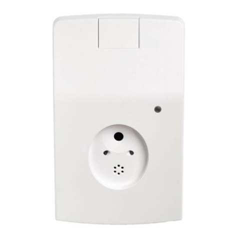
Allmatic A1H-U User manual

A
A1
1H
H-
-U
U
R
Ri
il
le
ev
va
at
to
or
re
e
d
di
i
p
pr
re
es
se
en
nz
za
a
v
ve
ei
ic
co
ol
li
i
a
a
s
sp
pi
ir
ra
a
m
ma
ag
gn
ne
et
ti
ic
ca
a
Manuale utente

A1H-U 2
6-1621238 rev.0 09/12/2013
CAUTIONS AND WARNINGS
CE REQUIREMENT: Use Pre-formed loops with built-in surge suppression for CE
compli nce. Connect shield on le d in wire to e rth ground.
CE REQUIREMENT: Use CE r ted power supply for CE compli nce providing
suppression s specified by EN61000-4-5.
Not to be used in person l s fety pplic tions.
When more th n one loop detector is used, set e ch one to different frequency.
Refer to DIP switch di gr m for frequency settings.
IMPORTANT:
This product is an accessory or part of a system. Always read and follow the manufacturer’s
instructions for the equipment before connecting this product. Comply with all applicable codes and
safety regulations. Failure to do so may result in damage, injury or death.
Specifiche tecniche
Sensibilità
10 livelli da 0 a 9
Display
Indica la sensibilità da 0 a 9
Aiuto diagnostica
Frequenza della s
pira
4 frequenze bassa, medio
-
bassa, medio
-
alta, alta)
Induttanza della spira
20…2000µH Fattore Q
>
5)
Regolazione automatica
Il rilevatore si accorda alla spira al momento
dell’alimentazione e dopo la misura della frequenza .
Adattamento am
bientale
Compensazione automatica
Protezione sovratensione
Sistema protetto da delle protezioni anti
-
sovratensione
incorporate
Relé
1 relè N.A./COM/N.C.)
Capacità del contatto
1A @ 24VDC…120VAC
Indicatore alimentazione /errore della spira
Led verd
e
Rilevamento /indicatore di frequenza
Led rosso
ASB Automatic Sensitivity Boost)
Aumenta automaticamente la sensibilità dopo il
rilevamento iniziale per evitarne la perdita in caso di
veicolo alto.
Alimentazione
12VDC…24VDC, 24VAC
Consumo Stand
-
by
/rilevamento)
15mA/45mA
Temperatura di funzionamento
-
40
˚C…82˚C
0…95% d’umidità relativa
Dimensioni L x l x h)
74mm x 23mm x 84mm
Modo di fissaggio
Guida DIN 35mm
Peso
113 g
Connettore
A vite

A1H-U 3
6-1621238 rev.0 09/12/2013
DESCRIZIONE GENERALE
Il prodotto A H-U con montaggio su guida DIN è compatibile con la maggior parte degli operatori per
cancelli. Può essere utilizzato come ingresso di sicurezza o ingresso di controllo . Il display dell’ A H-U
rende la regolazione molto semplice indicando l’ impostazione di sensibilità ottimale richiesta per individuare
la posizione di un veicolo sulla spira. Dieci regolazioni di sensibilità permettono un’impostazione precisa del
livello di rilevamento.
L’ A H-U presenta dei contatti in uscita che indicano la presenza di un veicolo. L’ A H-U permette di
regolare : ASB (aumento automatico di sensibilità), il tempo di risposta, la gestione in caso di rottura della
spira magnetica. Quattro regolazioni di frequenza permettono una buona flessibilità evitando interferenze
con altri rilevatori.
FUNZIONAMENTO
Alimentazione
All’accensione il rilevatore si configura regolandosi automaticamente con la spira. Il led verde indica
che il rilevatore è alimentato e funziona.
Regolazione della frequenza
La frequenza di utilizzo della spira è funzione dell’induttanza della spira utilizzata e delle
impostazioni dei DIP e 2. Il primo obiettivo della regolazione di frequenza è di permettere
all’installatore di regolare l’ A H-U su frequenze differenti per installazioni con più spire. Dopo aver
cambiato l’impostazione delle frequenza premere il pulsante di reset per ripristinare il rilevatore. Per
verificare l’impostazione delle frequenza di una spira vedere la sezione misurazione di frequenza.
Per determinare se c’è un problema di interferenza tra due spire vicine, vedere il display dell’ A H-U
Visualizzazione della sensibilità
Il display di sensibilità dell’ A H-U semplifica l’installazione indicando l’impostazione di sensibilità
desiderato per rilevare un veicolo sulla spira. Per utilizzare questa funzione, osservare il display nel
momento in cui un veicolo si posizione sulla spira, prendere nota della cifra visualizzata e quindi
regolare questa sensibilità grazie al selettore.
Durante il funzionamento normale, quando nessun veicolo è sulla spira, il display non indica nulla. In
caso di interferenze, queste possono essere visualizzate sul display, in assenza di veicoli. Le
interferenze porteranno il display ad indicare un livello, solitamente di 8 o 9. Potrebbe rendersi
necessario osservare il display per almeno un minuto per constatare questo effetto. Cambiare
l’impostazione della frequenza per evitare interferenze.

A1H-U 4
6-1621238 rev.0 09/12/2013
Regolazione della sensibilità
Il selettore a 0 posizioni permette una regolazione precisa del livello di rilevamento. Il livello di
sensibilità aumenta dalla posizione 0 alla posizione 9, dove 0 è la più bassa. Normalmente la
maggior parte delle installazioni richiede una regolazione su 3 o 4. Il display di sensibilità semplifica i
tempi d’installazione indicando il livello di sensibilità richiesto per rilevare un veicolo sulla spira. Per
utilizzare questa funzione, osservare il display nel momento in cui il veicolo avanza sopra la spira.
Prendere nota della cifra visualizzata e regolare la sensibilità ( selettore) sulla cifra indicata.
Regolazione della frequenza
Premere il pulsante di reset e contare il numero di lampeggi del LED rosso. Ogni lampeggio
rappresenta 0KHz. Per facilitare l’eliminazione delle interferenze dovute ad altre spire vicine,
eseguire una misurazione delle frequenza su ogni rilevatore per verificare che le frequenze siano
differenti. Dopo un’ analisi di frequenza il rilevatore si resetta.
Aumento automatico della sensibilità
L’ASB aumenta la sensibilità dopo un primo rilevamento. Questa funzione è utile per evitare la
perdita di rilevamento dovuta ai veicoli alti. La sensibilità ritorna alla sua regolazione iniziale dopo
che il veicolo ha passato la spira. Un punto luminoso sul display indica che il sistema ASB è in
funzione.
Uscita presenza
Ci sono due possibilità di regolazione della presenza, presenza infinita o presenza normale.
Presenza infinita attiva l’uscita per far si che rimanga in modalità di rilevamento per tutta la durata in
cui il veicolo è presente sulla spira; in presenza normale se un veicolo resta sulla spira, esegue un
reset automatico dopo 5 minuti. NON UTILIZZARE LA REGOLAZIONE DI PRESENZA NORMALE
SE IL SISTEMA D’APERTURA NON E’ PROTETTO DA UN SECONDO SISTEMA DI SICUREZZA.
Tempo di risposta
L’impostazione « ritardo » dà un tempo di risposta di 2 secondi dopo che il veicolo è passato sulla
spira
In caso di guasto della spira
Il rilevatore di guasto attiva il relè di presenza in caso di guasto della spira.
Il rilevatore di sicurezza disattiva il relè di presenza in caso di guasto della spira.

A1H-U 5
6-1621238 rev.0 09/12/2013
Controlli e indicatori
REGOLAZIONE DELLA SENSIBILITA’
RILEVAMENTO / REGOLAZIONE DELLA FREQUENZA
ALIMENTAZIONE / INDICATORE DI GUASTO DELLA SPIRA
DISPLAY
Indica il livello di sensibilità richiesto per rilevare il veicolo
REGOLAZIONE DI FREQUENZA / RESET
Pulsante reset
AUMENTO AUTOMATICO DELLA SENSIBILITA’ (ASB)
PRESENZA
RITARDO (2 seco di)
NON UTILIZZATO
RILEVATORE DI GUASTO / RILEVATORE DI SICUREZZA
REGOLAZIONE DELLA FREQUENZA
Po
sizione
0…….9
Sensibilità
bassa……….alta
LED rosso
Presenza rilevata
on
Nessuna presenza
off
Regolaz.frequenza
lampeggian
te
LED verde
Normale
on
Corto
-
circuito
1 lampeggio veloce
Spira aperta
2 lampeggi veloci
Cambio improvviso
>20%)
3 lampeggi veloci
Indicatore di guasto
2 lampeggi lenti
DIP switch posizione 1
ASB in funzione
on
DIP switch posizione 2
NORMALE 5 mi
n.)
on
INFINITA
off
DIP switch posizione 3
RITARDO
on
4
5
DIP switch posizione 6
Rilevatore di guasto
on
Rilevatore di sicurezza
off
Posizione DIP switch
FREQUENZA
7
8
Bassa
on
on
Medio
-
bassa
on
off
Medio
-
alta
off
on
Alta
off
off

A1H-U 6
6-1621238 rev.0 09/12/2013
Connessione
Descrizione
Spira
2 Spira
3 Massa (Terra)
4 Alimentazione (
2VDC…24VAC/DC)
5 Alimentazione (
2VDC…24VAC/D
C)
6 Presenza
-
uscita relè A
–
N.A.
7 Presenza
-
uscita relè A
-
COM
8 Presenza
-
uscita relè A
–
N.C.
3
2
1
5
4
6
7
8

A1H-U 7
6-1621238 rev.0 09/12/2013
Soluzione dei problemi
Anomalia
Ca sa possibile
Sol zione
LED verde lampeggia
Spira in corto circuito o aperta
Verificare che la resist
enza della spira
sui morsetti del connettore sia tra 0.5 e
5 Ohm
2 lampeggi veloci del led
verde
La spira era già in corto
circuito o aperta
Controllare la resistenza della spira sui
morsetti del connettore
Il rilevatore resta in modalità
di rilevamento dopo che il
veicolo ha lasciato la spira
.
Difetto della spira
2. Problema di connessione
3. Perdita di connessione
.
Verificare l’isolamento a terra, deve
essere > 00 mega ohms
2. Verificare la connessione ai morsetti
3. Verificare la tenuta
4. Verificare l’indicazione di frequenza
sul display, verificare che non ci sia
frequenza residua in assenza di
veicolo, premere il pulsante reset per
resettare.
Rilevamento intermittente
.
Guasto della spira
2. Problema di connessione
3. Perdita di connessione
4. Interferenze tra 2 spire
.
Verificare l’isolamento a terra, deve
essere > 00 mega ohms
2. Verificare la connessione ai morsetti.
3. Verificare la tenuta
4. Impostare le altre spire su frequenze
differenti.
Nessun rilevamento
.
Spira in corto circuito o
aperta
2. Sensibilità della spira
impostata troppo bassa
.
Verificare che la resistenza della
spira su morsetti del connettore sia
tra 0.5 ohms e 5 ohms.
2. Quando un veicolo è sulla spira,
osservare il display, regolare la
sensibilità al livello indicato

A1H-U 8
6-1621238 rev.0 09/12/2013
Installazione della spira
•Il cavo che collega la spira al rilevatore deve essere avvolto come minimo 8 giri al metro.
2 m
3 m
Spira
2mx3m
1 m
2 m
Spira
1mx2m
Installation typique
-
Installazione tipi
ca
-
Typical installation
-
-
Instalación tÍpica
Mesures conseillées pour l'enfouissement de la spire
(vue en section)
Misure consigliate per l’interramento della spira
(vista in sezione)
Suggested measures for loop burying
(section view)
Medidas aconsejadas para el enterrado de la espira.
(vista en sección)
10 ÷ 15 mm
30
÷
50
mm
SPIRA
Détecteur - Rilevatore - Loop detector -
Detector
Detécteur - Rilevatore - Loop detector –
Detector
Câble - Cavo – Cable
– Cable
2 x 0,5 mm
2
, l= 25m
(conforme alla dir. CEI 20
-
22 II)
Câble - Cavo – Cable –
Cable
2 x 0,5 mm
2
, l= 25m
(conforme
alla dir.
CEI 20
-
22 II)

A1H-U 9
6-1621238 rev.0 09/12/2013
ALLMATIC S.r.l
32020 Lentiai - Belluno – Italy
Via dell-Artigiano, n° – Z.A.
Tel. 0437 75 75 – 75 63 r.a. Fax 0437 75 065
http://www.allmatic.com - E-mail: in[email protected]m
GARANZIA - La garanzia del produttore ha validità a termini di legge dalla data stampigliata sul prodotto ed
è limitata alla riparazione o sostituzione gratuita dei pezzi riconosciuti dallo stesso come difettosi per
mancanza di qualità essenziali nei materiali o per deficienza di lavorazione. La garanzia non copre danni o
difetti dovuti ad agenti esterni, deficienza di manutenzione, sovraccarico, usura naturale, scelta del tipo
inesatto, errore di montaggio, o altre cause non imputabili al produttore. I prodotti manomessi non saranno
né garantiti né riparati.
I dati riportati sono puramente indicativi. Nessuna responsabilità potrà essere addebitata per riduzioni di
portata o disfunzioni dovute ad interferenze ambientali. La responsabilità a carico del produttore per i danni
derivati a chiunque da incidenti di qualsiasi natura cagionati da nostri prodotti difettosi, sono soltanto quelle
che derivano inderogabilmente dalla legge italiana.


A
A1
1H
H-
-U
U
V
Ve
eh
hi
ic
cl
le
e
L
Lo
oo
op
p
D
De
et
te
ec
ct
to
or
r
Operating Instructions

A1H-U 2
6-1621238 rev.0 09/12/2013
CAUTIONS AND WARNINGS
CE REQUIREMENT: Use Pre-formed loops with built-in surge suppression for CE
compli nce. Connect shield on le d in wire to e rth ground.
CE REQUIREMENT: Use CE r ted power supply for CE compli nce providing
suppression s specified by EN61000-4-5.
Not to be used in person l s fety pplic tions.
When more th n one loop detector is used, set e ch one to different frequency.
Refer to DIP switch di gr m for frequency settings.
IMPORTANT:
This product is an accessory or part of a system. Always read and follow the manufacturer’s
instructions for the equipment before connecting this product. Comply with all applicable codes and
safety regulations. Failure to do so may result in damage, injury or death.
Specifications
Sensitivity
10 levels, 0
-
9
Display
Indicates optimum sensitivity level, 0
-
9
Diagnostic aid
Loop frequency
4 settings (l
o , med
-
lo , med
-
hi, high)
Loop inductance
20…2000µH (Q factor
>
5)
Grounded loop
Isolation transformer allo s operation ith poor quality
loops
Automatic tuning
Detector tunes to loop on po er
-
up and follo ing
frequency count function
Environmental tr
acking
Automatic compensation
Surge protection
Loop circuitry protected by surge suppressors
Presence relay
SPDT relay contacts (form C)
Contact ratings
1A @ 24VDC…120VAC
Po er / loop fault indicator
Green LED
Detect / frequency count indicator
Red L
ED
ASB (Automatic Sensitivity Boost)
Increases sensitivity after initial detection to prevent
dropout due to high-bed vehicles
Po er
12VDC…24VDC, 24VAC (see Cautions and Warnings)
Operating Current (Standby/detect)
15mA/45mA
Operating temperature
-
40
˚
C…82
˚C (
-
40
˚F…180˚F)
0…95% relative humidity
Dimensions (L x W x H)
2.9”(74mm) x 0.9”(23mm) x 3.3”(84mm)
Mounting method
DIN rail mount
-
35mm
Weight
0.25 lbs. (113 g)
Connector
8 scre terminals

A1H-U 3
6-1621238 rev.0 09/12/2013
PRODUCT OVERVIEW
The A1 -U rail mount, vehicle loop detector is compatible with most gate operators. The A1 -U may be
used in Center, Safety and Exit loop positions. The display feature makes set-up easy by displaying the
optimum sensitivity setting required to detect a vehicle positioned on the loop. Ten sensitivity settings allow
for fine adjustment of detection level.
The A1 -U provides relay contact outputs indicating vehicle presence. The A1 -U features automatic
sensitivity boost (ASB), delay, fail-safe/fail-secure and infinite or normal (5 min.) presence. Four frequency
settings provide flexibility in preventing crosstalk in multi-loop applications.
OPERATION
Power up
Upon power up the detector initializes by automatically tuning to the loop. The green LED indicates
that the detector is powered and operational.
Frequency setting
The operating frequency of the loop is a function of the specific loop inductance and DIP switch
settings 1 and 2. The primary purpose of the frequency setting is to allow the installer the ability to
set different operating frequencies for multi-loop installations, recommended to prevent
crosstalk/interference from adjacent loops. After changing the frequency setting, press the
Frequency Count switch to re-initialize the detector. To check the operating frequency of a loop refer
to the Frequency Count section. To determine whether crosstalk between adjacent loops is
occurring, refer to the Sensitivity Display section.
Sensitivity Display
The sensitivity display simplifies the installation process by displaying the sensitivity setting required
to detect a vehicle on the loop. To use this feature, observe the display while a vehicle is moving
into position on the loop, note the number displayed, then adjust the sensitivity setting (rotary switch)
to the displayed position.
During normal operation, when a vehicle is not on the loop, the display is blank. The effects of
crosstalk or other interference can be observed on the display when the loop is vacant. Interference
or crosstalk will cause the display to indicate a level, typically 8 or 9. It may be necessary to observe
the display for a minute or so to see this effect. Change the frequency setting to prevent crosstalk.
Sensitivity setting
The 10-position rotary switch allows for precise adjustment of detection level. The sensitivity level
increases from position 0 thru 9 with position 0 being the lowest sensitivity. Typical applications
require a setting of 3 or 4. The sensitivity display simplifies the installation process by displaying the
sensitivity setting required to detect a vehicle on the loop. To use this feature, observe the display
while a vehicle is moving into position on the loop, note the number displayed, then adjust the
sensitivity setting (rotary switch) to the displayed position.

A1H-U 4
6-1621238 rev.0 09/12/2013
Frequency Count / Reset
Press the Frequency Count switch and count the number of flashes on the red LED. Each flash
represents 10k z. To help to prevent crosstalk when multiple detectors are used for adjacent loops,
perform a frequency count on each detector to confirm the operation frequencies are different.
Following a frequency count cycle, the detector re-initializes
Automatic Sensitivity Boost
The Automatic Sensitivity Boost causes the sensitivity to increase following initial detection. This
feature is useful to prevent dropout when detecting high-bed vehicles. The sensitivity returns to its
normal setting after the vehicle exits the loop. Decimal point on the display indicates ASB on.
Presence output
The Presence settings provides two selections, the output can be set for Infinite Presence or Normal
Presence. Infinite Presence causes the output to remain in detect mode as long as the vehicle
remains on the loop. Normal Presence causes the output to reset after 5 minutes. DO NOT USE
THE NORMAL PRESENCE SETTING UNLESS THE OPENING IS PROTECTED BY A
SECONDARY SAFETY DEVICE.
Delay
The Delay setting provides a 2 second delay before activating after a vehicle enters the loop, for both
Presence and Output B (except when output B is set to Detect-On-Stop).
Fail Safe / Fail Secure
Fail Safe setting causes the A1 -U to activate the Presence output in the event a loop failure. Fail
Secure setting will cause the A1 -U not to activate the Presence output in the event a loop failure.

A1H-U 5
6-1621238 rev.0 09/12/2013
Controls and Indicators
SENSITIVITY SETTING
DETECT / FREQUENCY COUNT
POWER / LOOP FAULT INDICATOR
ULTRAMETER™ DISPLAY
Indicates sensitivity setting required to detect vehicle
FREQUENCY COUNT / RESET
Press to start frequency count, re-initializes after count
AUTOMATIC SENSITIVITY BOOST
PRESENCE
DELAY (2 secon s)
SPARE (not use )
FAIL SAFE / SECURE
FREQUENCY SETTINGS
Position 0…….9
Sensitivity
Lo ……….high
Red LED
Presence detected
on
No presence
off
Frequency count
flashing
Green LED
Normal
operation
on
Shorted loop
1 fast flash
Open loop
2 fast flashes
Abrupt change (>20%)
3 fast flashes
Previous loop fault
2 slo flashes
DIP s itch position 1
ASB enabled
on
DIP s itch position 2
NORMAL (5 min.)
on
INFINITE
off
DIP s itch position 3
DELAY
on
5
4
DIP s itch position 6
Fail Secure
on
Fail Safe
off
DIP s itch position
FREQUENCY
7
8
Lo
on
on
Medium lo
on
off
Medium high
off
on
High
off
off

A1H-U 6
6-1621238 rev.0 09/12/2013
Connections
Descr
iptio
1
Loop
2
Loop
3
Shield
–
EART GROUND
4
Power (
12VDC…24VAC/DC)
5
Power (
12VDC…24VAC/DC)
6
Presence
-
Output A
–
N.O.
7
Presence
-
Output A
-
COM
8
Presence
-
Output A
–
N.C.
3
2
1
5
4
6
7
8

A1H-U 7
6-1621238 rev.0 09/12/2013
roubleshooting
Symptom
Possible cause
Solutio
Green
LED flashes
Loop wire shorted or open
Check loop resistance on the
appropriate loop pins on the control
board connector, between .5 ohms and 5
ohms.
Green LED flashes, 2 fast
Loop was previously shorted
or open
Check loop resistance on the
appropriate loop pins on the control
board connector.
Detector remains in detect
after vehicle has left loop
1.
Faulty loop
2. Poorly crimped terminals
3. Loose connections
1.
Perform megger test from loop lead
to ground, should be >100 megohms
2. Check loop connections to terminals
3. Check splices are properly soldered
and sealed against moisture
4. Observe display, level indicated on
display indicates residual frequency
shift from vacant loop to vehicle
presence, press Frequency Count
switch to re-initialize the detector
Intermitte
nt detection
1.
Faulty loop
2. Poorly crimped terminals
3. Loose connections
4. Cross-talk between
adjacent loops
1.
Perform megger test from loop lead
to ground, should be >100 megohms
2. Check loop connections to terminals
3. Check splices are properly soldered
and sealed against moisture
4. Set adjacent loops to different
frequencies (see Frequency Setting)
No detection
1.
Loop wire shorted or open
2. Loop sensitivity set too low
1.
Check loop resistance on the
appropriate loop pins on the control
board connector, between .5 ohms
and 5 ohms.
2. With vehicle on loop, observe
display, set sensitivity to the level
indicated on the display

A1H-U 8
6-1621238 rev.0 09/12/2013
Loop Installation
•The cable that connects the loop with the detector must be turned at least 18 times per meter.
2 m
3 m
Loop
2mx3m
1 m
2 m
Loop
1mx2m
Installation typique
-
Installazione tipica
-
Typical installation
-
-
Instalación tÍpica
Mesures conseillées pour l'enfouissement de la spire
(vue en section)
Misure consigliate per l’interramento della spira
(vista in sezione)
Suggested measures for loop burying
(section view)
Medidas aconsejadas para el enterrado de la espira.
(vista en sección)
10 ÷ 15 mm
30
÷
50
mm
LOOP
Détecteur - Rilevatore - Loop detector -
Detector
Detécteur - Rilevatore - Loop detector –
Detector
Câble - Cavo – Cable
– Cable
2 x 0,5 mm
2
, l= 25m
(
In compliance with
dir. CEI 20
-
22 II)
Câble - Cavo – Cable –
Cable
2 x 0,5 mm
2
, l= 25m
(
In compliance with
dir.
CEI 20
-
22 II)

A1H-U 9
6-1621238 rev.0 09/12/2013
ALLMATIC S.r.l
32020 Lentiai - Belluno – Italy
Via dell-Artigiano, n°1 – Z.A.
Tel. 0437 751175 – 751163 r.a. Fax 0437 751065
http://www.allmatic.com - E-mail: in[email protected]m
GUARANTEE - In compliance with legislation, the manufacturer’s guarantee is valid from the date stamped
on the product and is restricted to the repair or free replacement of the parts accepted by the manufacturer
as being defective due to poor quality materials or manufacturing defects. The guarantee does not cover
damage or defects caused by external agents, faulty maintenance, overloading, natural wear and tear,
choice of incorrect product, assembly errors, or any other cause not imputable to the manufacturer.
Products that have been misused will not be guaranteed or repaired.
Printed specifications are only indicative. The manufacturer does not accept any responsibility for range
reductions or malfunctions caused by environmental interference. The manufacturer’s responsibility for
damage caused to persons resulting from accidents of any nature caused by our defective products, are
only those responsibilities that come under Italian law.

Other manuals for A1H-U
1
Table of contents
Languages:
Other Allmatic Security Sensor manuals
