Allmess Itron UltraLite Instruction manual

GENERAL INSTRUCTIONS
Measuring capsule heat meter UltraMaXX
Screw-in heat meter UltraLite
These instructions apply to the following UltraMaXX models:
NX / MX / M4WX / 4WX / EVX / MP2X / RRX / RF24
CONTENTS PAGE
Notes 2
Proper disposal / lithium batteries in equipment 3
Installation instructions
Installation instructions flow rate sensor screw-in heat meter
CF-UltraMaXX 4 - 5
Installation instructions
Temperature sensor
Information on identification of immersion sleeves 6 - 7
Installation instructions
Temperature sensor
DS 6 and AGFW according to EN 1434 8
Installation instructions
Temperature sensor Ø 5.0 or 5.2 mm 9
Commissioning and sealing 10
Connection diagram options 11
Instruction manual 12 - 15
Instruction manual options 16 - 18
Notes 19
2 3
IMPORTANT BEFORE INSTALLATION
Hot water networks operate at high temperatures and high pressures, which
can cause serious bodily injury if handled improperly. Therefore the measuring
devices may only be installed by qualified and trained personnel. The pipes must
be earthed. The installation of a heat meter must be carried out in accordance
with the recognised technical regulations (e.g. EN 1434-6) in such a way that
a correct measurement value can be recorded. The reading must be possible
without any additional aids, and trouble-free deinstallation of the individual com-
ponents must be possible after the validity of the calibration has expired! Small calculator unit
Big calculator unit
IN ADDITION, THE FOLLOWING MUST BE OBSERVED
• Permissible ambient temperature (from 5° C to 55° C)
• Sealing the flow sensor itself and the temperature sensor is important and prevents
unauthorised deinstallation.
• Flush the pipe system thoroughly before installing the flow sensor.
• According to EN 1434-6, the calculator/flow sensor/signal cables (e.g. sensor
cables) must not be installed/routed near live mains cables and/or sources of
electromagnetic interference (min. 50 mm distance).
• Caution: Special care is required in the case of particularly strong sources of
electromagnetic interference, e.g. machines, frequency converters, power inverters,
circuit breakers, high-voltage pumps and neon tubes, and the distance to the signal
cables of the heat meter must be increased to 50 cm.
• ESD compliant installation for external cables according to EN 61340-5.
• Environmental class C according to EN 1434-1 as well as E1 and M1 according
to directive 2014/32/EU.
• The flow sensor must never be lifted or transported using the connection cable!
• Do not route cables along hot pipes.
• Big arithmetic unit
• The heat meter has protection class IP54 as standard. In the model with the large casing, the heat meter has protection
class IP20 in the area of the connection terminals.
• Opening a security seal will result in loss of the compliance and guarantee.
• Cleaning the casing must only be carried out from the outside with a soft, slightly moistened cloth - do not use cleaning
agents.
• Do not carry out welding anywhere near the meter.
• The meter should remain in the original packaging until all connection, insulation, painting and flushing work is completed.
• Always install the meter according to the mounting position printed on the serial plate (supply or return).
• The flow sensor can be installed either horizontally or vertically in any mounting position.
• The heat meter must be protected against damage caused by shocks or vibrations that may occur in the installation
location. During commissioning, the shut-off valves must be opened slowly.
• Threaded connections on the meter must correspond with the respective counterparts of the pipe in nominal diameter
DN and nominal pressure PN (according to EN 1092). Do not expose the meter to excessive stresses caused by pipes
or fittings. The pipes of the heating system must be sufficiently anchored in front of and behind the heat meter. All
screws, nuts and seals used must be designed for the rated values DN, pressure rating PN, maximum temperature and
maximum permitted pressure.
INSTALLATION NOTE
The use of the heat meter temperature sensor is only permitted in conjunction with corresponding temperature sensor mea-
suring points approved for the sensor. Both measuring points of a heat meter must be designed in the same way.
A combination of immersion sleeve and direct measurement is forbidden.
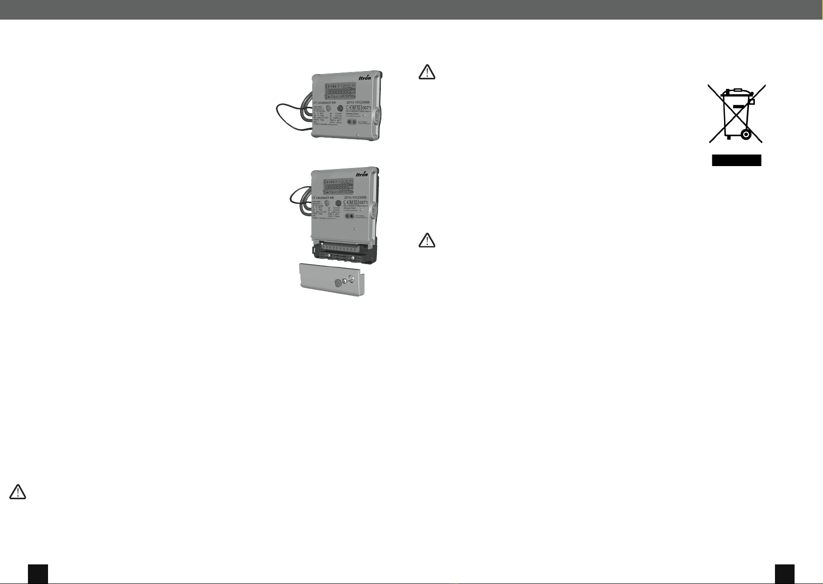
NOTES PROPER DISPOSAL · LITHIUM-BATTERIES IN EQUIPMENT
NOTES PROPER DISPOSAL
INFORMATION ON THE APPROPRIATE DISPOSAL OF PRODUCTS
The crossed out wheelie bin symbol on the product or on its packaging indicates
that the used product should be recycled separately from household waste, so
that it can be properly treated and disposed of. Check with your local authori-
ties about the location of recycling centres, so that the product can be recycled
appropriately. If an equivalent new device is purchased, the seller must take back
the used device for recycling. The product is not potentially harmful to human
health and the environment, but if it is disposed of illegally in the environment,
it has a negative impact on the ecosystem. Illegal disposal of the device in the
environment is a punishable offence.
LITHIUM BATTERIES IN EQUIPMENT
NOTE ON LITHIUM BATTERIES
The device contains non-replaceable lithium-ion batteries. Do not charge the batteries, do not expose them to mechanical
stresses or temperatures above 100° C. In the event that replacing the batteries is possible, then this is explicitly described
in the installation instructions and/or instruction manual. There are transport regulations which must be observed for lithium
batteries. The certificates required for transport can be requested from the manufacturer.

4 5
INSTALLATION (FIG. 1)
Turn off the heating circulation pump and close the ball valves. Check the instal-
lation location (return / supply) to make sure this corresponds with the print on
the unit. Remove the distance piece and the seals, and if necessary, clean the
sealing surfaces.
Replacement:
• Turn off the circulation pump
• Close the shut-off valves and release pressure in the pipe
• Break open the seals and unscrew the temperature sensor from the supply
T-piece or from the supply ball valve
• Remove the old heat meter and the seals, and if necessary, clean the sealing
surfaces.
INSTALLATION OF A HEAT METER (FIG. 2)
Install the compact heat meter with new seals in the direction of the flow (follow
the flow direction arrows on the casing).
Caution: the cable must not be cut, squashed or damaged when
removing the unit and during installation!
Caution: ensure tension-free installation - if necessary, ensure that
the pipes are sufficiently anchored in front of and behind the heat
meter.
86
128
102
A
72
97
B
F
86
128
102
A
72
97
B
F
86
128
102
A
72
97
B
F
DEVICE DIMENSIONS
INSTALLATION INSTRUCTIONS FLOW RATE SENSOR SCREW-IN HEAT METER · CF-ULTRAMAXX INSTALLATION INSTRUCTIONS FLOW RATE SENSOR SCREW-IN HEAT METER · CF-ULTRAMAXX
Fig. 1
A B
130 mm 1”
or or
110 m m 3/4”
Fig. 2
INSTALLATION INSTRUCTIONS
Flow rate sensor screw-in heat meter
CF-UltraMaXX
Possibly accessories pack for temperature sensor installation:
• A hinged screw fitting (light grey) for immersion sleeve Ø 5.0 and 5.2
• Two brass screw fittings with O-ring and auxiliary tool for direct measurement. Accessories pack with direct measuring
adapter and copper seal. Two information signs for direct measurement.
• Identification plates for immersion sleeves
PACKAGE CONTENTS
• Compact heat meter
• Sealing material
• Wall mounting
• General instructions
6 7
INSTALLATION INSTRUCTIONS
Temperature sensor
INFORMATION ON IDENTIFICATION OF IMMERSION SLEEVES
When installing the heat meter, the following applies:
• both temperature sensor measuring points must be the same (e.g. 2 x TH6)
• immersion sleeve and direct measurement must not be combined
• temperature sensors must be approved for the relevant measuring point
(see marking of the measuring point)
Type of key GKey width
(SW)
Insertion
depth (E)
mm
for TH 6 mm with M 12 external thread
TH009 SW 14 50
TH010 SW 22 50
TH 011 SW 19 50
TH012 SW 22 50
for TH 5.0 mm with clamping screw
TH013 ¼SW17 49
TH015
3
/
8
SW17 60
TH017
3
/
8
SW22 56
TH018 ½SW22 60
TH020
3
/
8
SW22 49
TH021 ½SW22 49
TH029 M10x1 SW14 47
TH033 M10x1 SW14 56
TH035 M10x1 SW14 47
TH047 M10x1 SW17 46
TH051 ¼SW17 49
TH055 M10x1 SW17 49
TH083 M10x1 SW13 39
TH084 ¼“ SW17 40
TH085 ½“ SW27 40
TH086
3
/
8
SW22 40
TH087 M10x1 SW17 40
TH088 ¼“ SW17 40
TH090 M10x1 SW14 46
Bauart-
schlüssel
GKey width
(SW)
Insertion
depth (E)
mm
TH 5.2 mm with clamping screw
TH001 ½ SW24 42
TH002
3
/
8
SW24 42
TH003 ½ SW24 56
TH004 ½ SW24 53
TH005 ½ SW 30 52
TH040 ½ SW24 46
TH043
3
/
8
SW24 57
TH044 ½ SW24 57
TH046 M10x1 SW17 46
TH048 ¼ SW17 49
TH054 M10x1 SW17 49
TH067 ¼ SW17 59
TH068 ¼ SW17 69
TH077 M10x1 SW13 39
TH079 ½ SW24 39
TH081
3
/
8
SW17 39
TH089
3
/
8
SW22 53
TH091 M10x1 SW14 46
Example of a measuring point mark-
ing for immersion sleeves:
If the existing measuring points are not marked, they must be determined and marked. Usually, the internal diameter (use
sensor gauge part no. 14883), insertion depth and key width of the hexagon must be measured.
A determination can then be made using the following tables:
INSTALLATION INSTRUCTIONS FLOW RATE SENSOR SCREW-IN HEAT METER · CF-ULTRAMAXX INSTALLATION INSTRUCTIONS TEMPERATURE SENSOR · NOTES ON IDENTIFICATION OF IMMERSION SLEEVES
IDENTIFICATION OF THE MEASURING POINT TYPE
Immersion sleeves with M12
external threads
Measuring point type GKey width (SW) Insertion depth (E) mm
DS 6 6,2 mm SW 14 * > 51
EN 1434 3/8 SW 14 * < 46 (up to DN 25)
*Hexagon only on flow sensor
For comparison:
Representation of two direct measuring points of type DS6 or according to EN1434 (always with supply ball valve)
M12x1,5
for TH 6
E
SW
Measuring area
inside diameter
for TH 5,2/TH 5,0
SW
E
Measuring area
inside diameter
Immersion sleeves with
clamping screw
TH009
8 9
INSTALLATION INSTRUCTIONS TEMPERATURE SENSOR DS 6 AND AGFW ACCORDING TO EN 1434 INSTALLATION INSTRUCTIONS TEMPERATURE SENSOR Ø 5.0 OR 5.2 MM
INSTALLATION INSTRUCTIONS
Temperature sensor Ø 5,0 or 5,2 mm
INSTALLATION NOTE
The use of the heat meter temperature sensor is only permitted in conjunction with
corresponding temperature sensor measuring points approved for the sensor. Both
measuring points of a heat meter must be designed in the same way. A combination
of immersion sleeve and direct measurement is forbidden.
INSTALLATION OF A TEMPERATURE SENSOR
For heat/combi meters:
Insert the temperature sensor (red) into the supply measuring point and the
temperature sensor (blue) into the return measuring point.
For cold meters:
Insert the temperature sensor (blue) into the supply measuring point (cold pipe)
and the temperature sensor (red) into the return measuring point.
TEMPERATURE SENSOR IN IMMERSION SLEEVE
• Check the conformity of the nominal diameters of the temperature sensor and
immersion sleeves.
• Check the immersion sleeve according to the installation and handover report,
and mark with the supplied label (also see document in inner section).
• Attach the temperature sensor in the supply and return lines according to the
respective attachment type.
Immersion sleeves with capstan screws for sensors Ø 5.0 and 5.2 mm (Fig. 1)
• Insert the sensor completely into the immersion sleeve
• Tighten the capstan screw by hand.
Immersion sleeve with M 10x1 internal thread for sensors Ø 5.0 and 5.2 mm
(Fig. 2)
• 1. Insert the sensor into the plastic screw-in connection (light grey), place the two
upper flanges of the sensor in the two ribs of the screw-in connection
• 2. Close the screw-in connection
• 3. Tighten the sensor with screw-in connection in the immersion sleeve by hand.
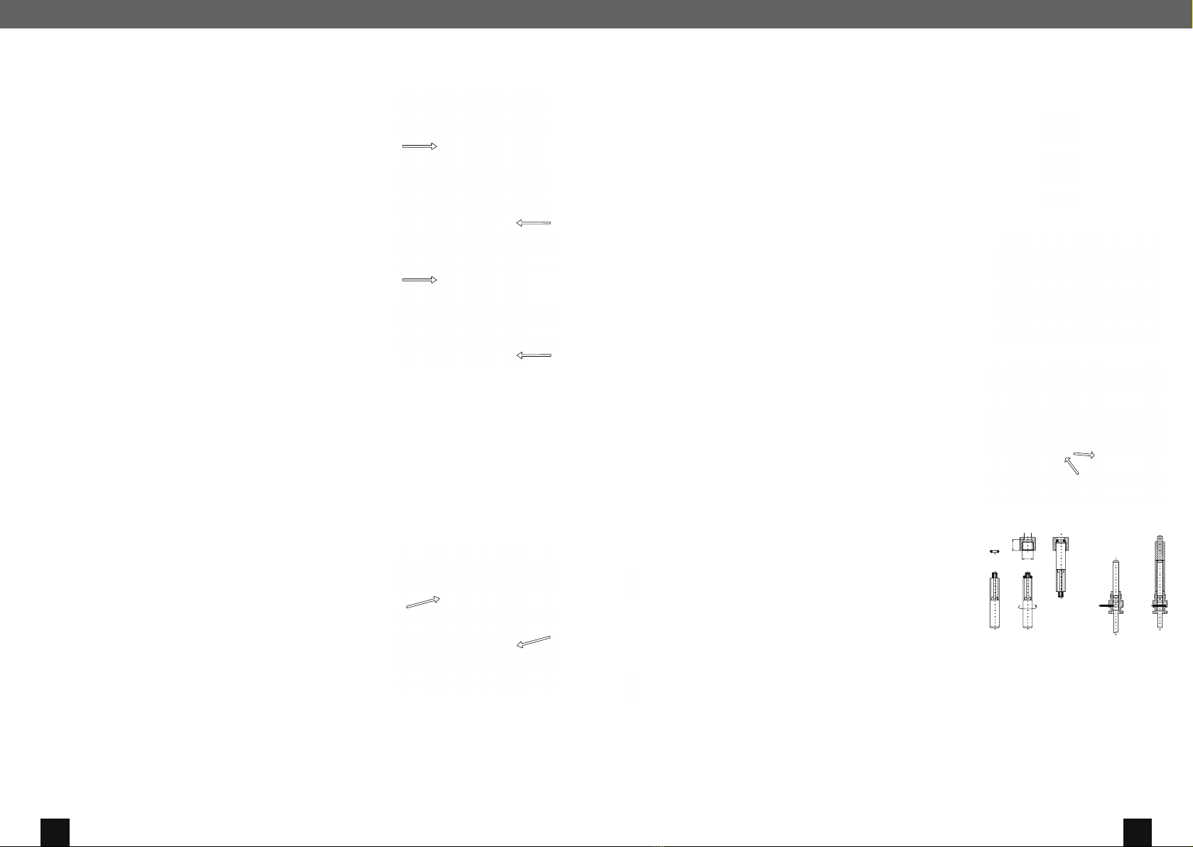
DIRECT MEASUREMENT TEMPERATURE SENSOR
ACCORDING TO EN 1434, CONVERSION OF INTEGRAL-V ULTRALITE
Ø 5.2 MM TO DIRECT MEASUREMENT (FIG. 3)
Caution:
Before conversion, block off the installation point, release pressure and drain.
• 1. Unscrew the immersion sleeve from the Integral-V and remove it along with
the seal.
• 2. Screw in the direct measuring adapter with the Cu seal supplied and tighten
to 13 Nm.
• 3. Attach information signs for direct measurement (red) to both sensors.
Fig. 1
Fig. 2
1. 2. 3.
1.
2.
3.
Fig. 3
1. 2. 3. 4. 5.
Fig. 4
Installing the sensors (Fig. 4)
Caution: : Before installing the sensors, block off the installation point, release pressure and drain.
• 1. Attach an O-ring from the set supplied to the installation aid.
• 2. Insert the O-ring using the installation aid into the installation point location according to DIN EN 1434 with a twisting motion.
• 3. Use the other end of the installation aid to finally position the O-ring in the installation point.
• 4. Position the brass screw-in connection correctly on the temperature sensor using the loosely inserted grooved pin.
• 5. Place the end of the installation aid over the temperature sensor sleeve and insert this as far as it will go (to determine the
sensor installation length). Align the brass screw-in connection flush with the installation aid and press in the grooved pin
(e.g. with a pair of pliers) to lock the temperature sensor sleeve.
• 6. Push the temperature sensor with the screw-in connection through the O-ring into the installation point right up to the
gasket and tighten by hand. Tightening torque 3 to 5 Nm.
INSTALLATION NOTE
The use of the heat meter temperature sensor is only permitted in conjunction
with corresponding temperature sensor measuring points approved for the sen-
sor. Both measuring points of a heat meter must be designed in the same way. A
combination of immersion sleeve and direct measurement is forbidden.
INSTALLATION OF A TEMPERATURE SENSOR
For heat/combi meters:
Insert the temperature sensor (red) into the supply measuring point and the
temperature sensor (blue) into the return measuring point on the EAT.
For cold meters:
Insert the temperature sensor (blue) into the supply measuring point (cold pipe)
and the temperature sensor (red) into the return measuring point on the EAT.
TEMPERATURE SENSOR IN IMMERSION SLEEVE (FIG. 1)
• Check the immersion sleeve according to the installation and handover report,
and mark with the supplied label (also see document in inner section).
• Insert the temperature sensor completely into the immersion sleeve, screw in
and tighten by hand.
DIRECT MEASUREMENT TEMPERATURE SENSOR DS 6 (FIG. 2)
Unscrew the dummy caps of the temperature sensor measuring points (make
sure that the ball valves are closed) and remove them along with seals.
• Screw in the temperature sensor and tighten to 5-8 Nm.
Fig. 2
Supply
Return
Fig. 1
UltraMaXX
Supply KH DS 6
Supply
Return
UltraMaXX
supply T-piece TH
INSTALLATION INSTRUCTIONS
Temperature sensor DS 6
INSTALLATION INSTRUCTIONS
Temperature sensor AGFW according to EN 1434
INSTALLATION NOTE
See installation note above (temperature sensor DS 6)
INSTALLATION OF A TEMPERATURE SENSOR
For heat/combi meters:
Insert the temperature sensor (red) into the supply measuring point and the
temperature sensor (blue) into the return measuring point.
For cold meters:
Insert the temperature sensor (blue) into the supply measuring point (cold pipe)
and the temperature sensor (red) into the return measuring point.
DIRECT MEASUREMENT TEMPERATURE SENSOR AGFW EN 1434 (FIG. 1)
Unscrew the dummy plugs of the temperature sensor measuring points (make sure
that the ball valves are closed) and remove them along with seals.
• Insert the temperature sensor into the measuring points as described above with
a new seal.
• Screw in the temperature sensor and tighten to 10 Nm.
Fig. 1
Supply
Return

10 11
CONNECTION DIAGRAM
Options
Large calculator:
Remove the user seal on the cover screw. Expose the screw terminals by opening the cover (screw). Connect the cable
according to the diagram and secure strain-free. Break the corresponding cable holes out of the cover. Screw on the cover
and secure the screw with a new user seal.
Small calculator Large calculator
blue
white
black
red
brown
white
Remote display of
energy / volume
M-BUS
M-Bus 4 water meter
M-BUS
with power supply
2 water meters
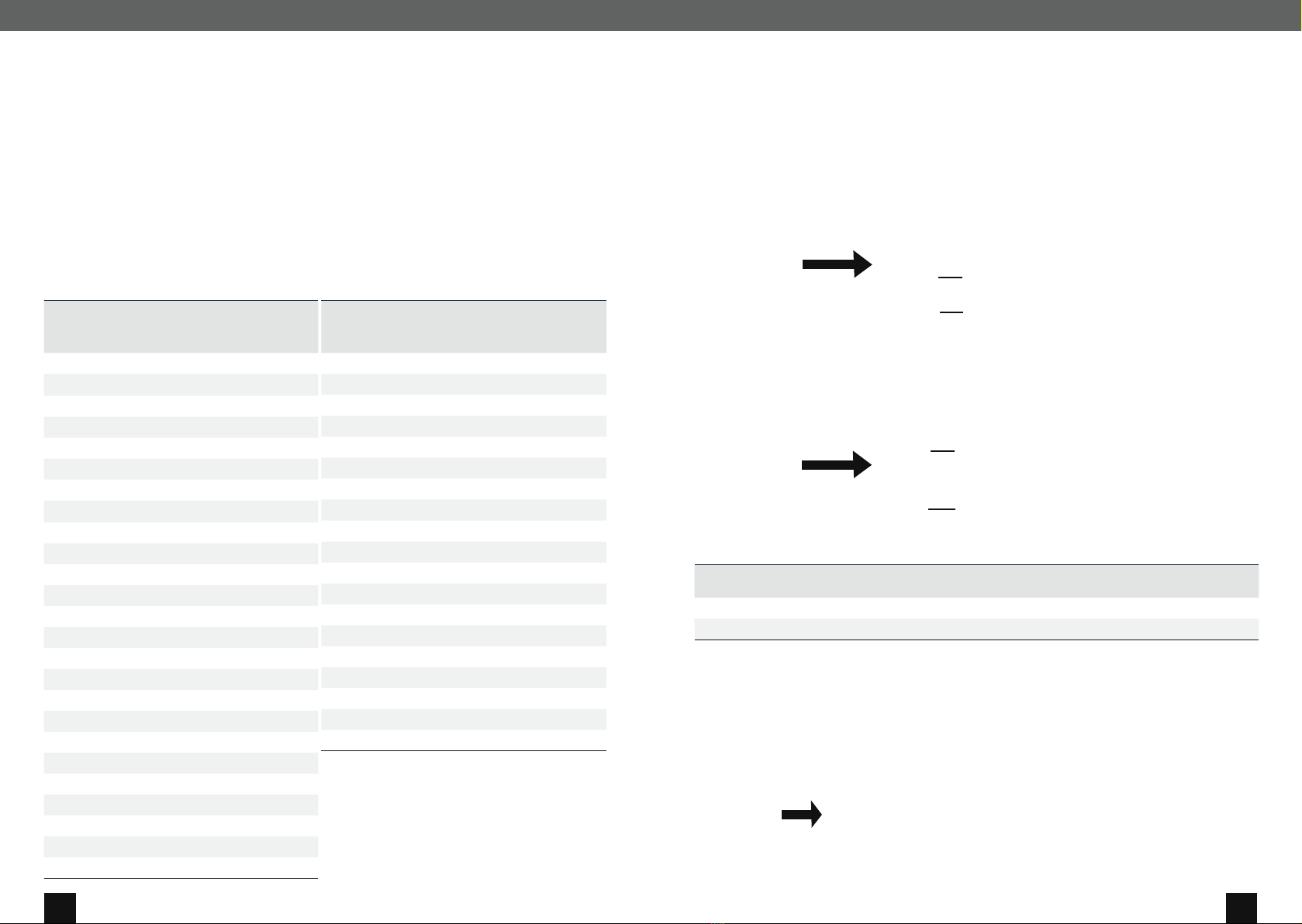
SPECIFICATIONS
Specification for pulse output for energy and
volume remote display*
Scanning voltage max. 30 V, min. 2,5 V
Max. permissible 20 mA
Max. internal
resistance Ron 100 Ω (during remote display pulse)
Pulse width 120 ms
Pulse value Energy: 1 KWh (or 10 MJ),
Volume: 10 l
Pulse
characteristics Pull-Down circuit
*) In the factory option “Combi” for use in combined heat and
cold systems, the pulse output labelled “V” is used as a cold
energy pulse (1 kWh).
Input specification for water meter
Pulse value
1 / 2.5 / 10 / 25 / 100 or 250 l / pulse
(programmable via push-button,
same pulse value for all connected
water meters)
Scanning voltage typically 3 V
Pulse detection Contact closed R < 500 Ω /
contact open R > 1 MΩ
Pulse length/pause > 3 s each
Cable length max. 10 m
Specification of the M-Bus interface:
Standard reference EN 13757-3
Baud rate /
Protocol
300 baud / 2.400 baud / variable
Protocol, low-byte-first
Default data
Manufacturer number, energy,
volume, power, flow rate, tempe-
ratures (supply, return, difference),
operating time, date and time,
optional volume water meter 1...4,
firmware version, software version
18 key date
data sets
Energy, volume, optional maximum
values of power, flow rate and sup-
ply temperature with time stamp,
volume of water meter 1...4
CONNECTION DIAGRAM CONNECTION DIAGRAM
COMMISSIONING (FIG. 1)
Open the ball valves / shut-off valves. Switch on the circulation pump. Check for
leaks.
PLAUSIBILITY CHECK (FIG. 1)
Activate the unit display by pressing the push-button. Perform the LCD test.
Check the values for flow rate, supply temperature and return temperature for
plausibility, check the error display (see operating instructions).
Attention: To document the plausibility check, please fill in the installation
handover report (removable page in inner section).
SEALING MK (FIG. 2)
Secure the head ring with a red plug-in seal (barb to the centre of the housing)
and the supply and return temperature sensors with a sealing sleeve, to prevent
unauthorised deinstallation. Alternatively, the temperature sensors can be
secured with the supplied wire and metal snap-on seal. If necessary in the event
of incorrect installation, break open the seal with a screwdriver, and secure again
with a metal snap-on seal after the installation has been corrected.
SEALING V (FIG. 3)
Secure the screw-in connection of the meter and the supply and return
temperature sensor with wire and metal snap-on seal, to prevent unauthorised
deinstallation.
UNIT INSTALLATION (FIG. 4)
Place the unit on the flow rate sensor/wall mounting bracket and press down until
it locks into place.
Fig. 1
Installation
Fig. 2
Seal
CLICK
Deinstallation
Fig. 3 Seal
Wall mounting bracket on a pipe Unit on the wall mounting
bracket on the wall
Unit on wall mounting
bracket with magnet in
cabinet
Cable ties
Length of connecting cable for flow rate sensor/unit: 0.5 m
Fig. 4
COMMISSIONING AND SEALING
12 13
INSTRUCTION MANUAL
INSTRUCTION MANUAL
EXPLANATION OF THE DISPLAYS
1. LCD level consumption data
1.1 Cumulative energy in kWh, MWh or GJ
1.2 Cumulative volume in m3
1.3 Segment test (function test of all display segments)
2. LCD level key date values
The UltraMaXX stores the respective cumulative end-of-month values for energy and volume for the last 18 months. These
values are shown in the 2nd LCD level. The display starts with the month-end value of the cumulative energy of the previous
month in relation to the reading date, and then goes one month back into the past every 2 seconds until the 18th month
value is reached.
From the 18th month value, the display then jumps back to the
1st display value (previous month).
2.1 / 2.1.1 Month-end value energy previous month
2.1.2 Month-end value volume previous month
2.2 / 2.2.1 Month-end value energy 2 months back
2.2.2 Month-end value volume 2 months back
2.3 / 2.3.1 Month-end value energy 3 months back
2.3.2 Month-end value volume 3 months back
2.4 - 2.17 see above
2.18 / 2.18.1 Month-end value energy 18 months back
2.18.2 Month-end value volume 18 months back
3. LCD level service data
3.1 current flow in m3/h.
3.2 current power in kW
3.3 current supply temperature in °C.
3.4 current return temperature in °C.
3.5 current temperature difference in °C.
3.6 Time in error state in hours (h)
3.7 Operating time
3.8 Time with excessive flow in hours (h)
3.9 Error code:
1 - Error supply sensor >> Check supply sensor including cable for integrity and correct installation
2 - Error return sensor >> Check return sensor including cable for integrity and correct installation
3 - Temperature sensor reversed >> Check correct installation of temperature sensor
4 - Error A/D converter >> Replace device with new device
5 - Return flow in flow rate sensor >> Check correct installation (flow direction) of the flow rate sensor and/
or the EATs
6 - Air in flow rate sensor >> Flush air from flow rate sensor with high flow or no communication with flow
rate sensor. Cable damaged >> Replace device with new device
7 - Current flow rate above maximum flow rate >> Reduce flow rate in flow rate sensor
8 - Error electronics >> Replace device with new device
In the event of multiple errors, these are displayed simultaneously (e.g. 12---6--)
3.10 Firmware version
Month
Value
Year
Unit
Month
Value
Year
Unit
Years
Days (d)
INSTRUCTION MANUAL
OPTIONAL DISPLAYS
(DEPENDING ON OPTIONS ORDERED)
1.4 Cumulative cold energy for combi meters,
heat energy is displayed in 1.1
1.5 Energy year-end key date
1.6 Cold energy year-end key date for combi meters
1.7 Volume water meter 1
1.8 Volume water meter 2
1.9 Volume water meter 3
1.10 Volume water meter 4
1.11 Threshold value tariff 1
1.12 Energy above threshold value 1
1.13 Volume above threshold value 1
1.14 Threshold value tariff 2
1.15 Energy above threshold value 2
1.16 Volume above threshold
value 2 x = 1-18 months with key date function
2.x.3 Month-end value cold energy in combi
meters x months back
2.x.4 Volume water meter 1 x months back
2.x.5 Volume water meter 2 x months back
2.x.6 Volume water meter 3 x months back
2.x.7 Volume water meter 4 x months back
2.x.8 Maximum value power x months back
2.x.8.1 Value
2.x.8.2 Time
2.x.8.3 Date
2.x.9 Maximum value flow rate x months back
2.x.9.1 Value
2.x.9.2 Time
2.x.9.3 Date
2.x.10 Maximum value temperature x months back
2. x .10 .1 Va lue
2. x .10 . 2 Time
2.x.10.3 Date
3.11 Maximum value power
3.11.1 alu e + t i m e
3.11.2 Value + day
3.11.3 Value + year
3.12 Maximalwert des Durchflusses
3.12.1 Wert + Uhrzeit
3.12.2 Wert + Tag
3.12.3 Wert + Jahr
3.13 Maximum value of temperature
3.13.1 Value + time
3.13.2 Value + day
3.13.3 Value + year
3.14 Threshold value temperature difference for
combi meter
3.15 Threshold value supply temperature for
combi meter
3.16 Date and time
3.17 M-Bus primary address
3.18 M-Bus secondary address
3.19 Baud rate communication interfaces
3.20 Water meter pulse value
3.21 Water meter number
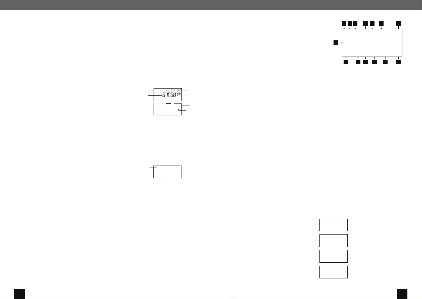
DISPL AY
A Service figure:
- Energy measurement
stopped
B Warning
US signal level:
- Low signal level
C Temperatures:
- permanent:
Tv, Tr or T
- flashing. error
D Metrology indicator:
- Display value
for business traffic
allowed (country
dependent)
E Flow rate indicator:
- permanent: flow rate
- flashing: no flow
F Date and time
stamp:
- e.g. key date values,
max. values
G Display level:
- Currently selecte
display level
H Units:
- Physical unit
I Pulse value:
- External water
meters
J Maximum value:
- Power, flow rate,
supply T
K Battery symbol:
- Check calibration
validity
L Tariff function
M External water
meters:
- Number of water
meters connected
N Main display 8
digits:
- Digit size:
6.5 x 3.3 mm
N
A B C D E F G
HIJKLM
POSSIBLE DISPLAYS IN THE EVENT OF
MALFUNCTIONS
When the service figure is shown on the display, the energy
calculation is interrupted. Possible errors are indicated in the
warning messages display code (3.9).
Meter in unprogrammed state.
Replace device with a new device.
No value for current flow rate (3.1). See
warning message in the display 3.9.
No value for current power (3.2). See
warning message in the display 3.9.
No value for current supply tempera-
ture, return temperature or temperature
difference (3.3, 3.4 or 3.5). See warning
message in the display 3.9.

14 15
INSTRUCTION MANUAL
ARRANGEMENT AND OPERATION OF THE DISPLAY
1. level: consumption data 2nd level: key date values 3rd level: service data
INSTRUCTION MANUAL
Approx. 4 minutes after the last press of the button, the
display of the meter switches off.
= brief button press (shorter than
2 seconds)
= longer button press (longer than
2 seconds)
= automatic display change
(approx. every 2 seconds)
= standard displays
= optional displays (depending on
options ordered)
- Activation of the display by
a brief button press
- Change the display within one level by
brief button press
- Change to another level by
longer button press
- In level 2 (key date values), an
automatic change of display ( ) of
the key dates begins, starting with the
energy value of the previous month.
Ashort button press while a
certain key date is displayed will display
further values for that key date.
Operation of the liquid-crystal display (LCD)

16 17
INSTRUCTION MANUAL OPTIONS
OPTION M-BUS
The optional M-Bus option allows the UltraMaXX to be
connected to a wired M-Bus remote reading system. The
communication parameters primary address, secondary
address and baud rate can be displayed via the liquid-crys-
tal display (LCD). The parameters can be set by authorised
service personnel using the service software via the optical
interface / M-Bus option, or set directly via the buttons on
the UltraMaXX.
Default factory setting:
Primary address: 0
Secondary address: Meter
number baud rate: 2400 baud
Setting the M-Bus parameters using the buttons on the
device:
1) Remove the user seal above button 2
2) Use button 1 to display the value to be adjusted must
then be selected
Primary address: Display 3.17
Secondary address: Display 3.18
Baud rate: Display 3.19
3) Press button 2 for longer than 2
seconds: The display or the right
digit in the display flashes.
4) Set the desired value by pressing button
5) Press button 2: digit one position further to the left
flashes (only for primary/secondary address).
6) Repeat procedure 4.) and 5.) until the desired value is
set. Possible settings:
Primary address: 1 - 250
Secondary address: 00000001-99999999
Baud rate: 300, 2400 baud
7) Press button 2 for longer than 2 seconds to exit the
settings mode.
8) Secure button 2 against manipulation by means of a
new user seal.
OPTION WATER METER INPUTS
The UltraMaXX offers the option of connecting up to
4 water meters with a remote indicator output at the unit.
The meter readings of the water meters (displays 1.7 /
1.8 / 1.9 / 1.10), including the key date values (displays
2.X.4 / 2.X.5 / 2.X.6 / 2.X.7), can be read via the display,
M-Bus or optical interface on the UltraMaXX. The meter
readings, the number of water meters and the pulse value
of the water meters can be set by authorised service
personnel using the service software via the optical inter-
face / M-Bus option, or set directly via the buttons on the
UltraMaXX.
Programming water meter inputs:
1) Remove the user seal above button 2
Pulse value water meter
2) Use button 1 to select the water meter pulse value
display (3.20)
3) Press button 2 for longer than 2 seconds >> display
flashes
4) Use button 1 to set the desired value
5) Press button 2 for longer than 2 seconds to exit the
settings mode.
Number of water meters
6) Use button 1 to select the number of water meters
display (3.21)
7) Press button 2 for longer than 2 seconds >> display
flashes.
8) Use button 1 to set the desired value (1- 4).
9) Press button 2 for longer than 2 seconds to exit the
settings mode.
Meter reading of water meter
10) Use button 1 to select the volume display (1.7).
11) Press button 2 for longer than 2 seconds: the right
digit in the display flashes.
12) Set the desired value by pressing button 1.
13) Press button 2: the digit one position further to the left
flashes
14) Repeat procedure 12.) and 13.) until the desired value
is set.
15) Press button 2 for longer than 2 seconds to exit the
settings mode.
16) If required, repeat steps 10 to 15 for additional water
meters.
Water meter 2 >> display 1.8
Water meter 3 >> display 1.9
Water meter 4 >> display 1.10
17) Secure button 2 against manipulation by means of a
new user seal.
User seal
Button 1
INSTRUCTION MANUAL OPTIONS
INSTRUCTION MANUAL OPTIONS
Temperature-type Value
Tariff Unit
Condition
Temperature type:
Temperature difference
Supply temperature
Return temperature
Tariff:
1 Tariff 1
2 Tarfif 2
Unit:
°C Temperature
m3/h Flow rate
kW Power
Bedingung:
less than
greater than / equal to
TIME WINDOW
A time window can be selected as the tariff. The start time ( )
end time ( ) is represented as follows:
Energy above threshold value ½
Time above/below threshold value in
hours (h)
Energy value above/below threshold
value
Tariff (1 or 2)
Volume above threshold value ½
Time above/below threshold value in
days
Volume value above/below threshold
value
Tariff (1 or 2)
OPTION MAXIMUM VALUES
These optional displays show the current monthly
maximum values for power (3.11), flow rate (3.12) and
supply temperature (3.13) with time stamp. 18 maximum
monthly values are stored internally for each item, which
can be read out via M-Bus, optical interface or the LCD
display at the key date level (2.X.8 / 2.X.9 / 2.X.10). The
period duration for determining the maximum values
is 60 minutes. The period duration can be varied via
M-Bus or the optical interface with the help of the service
software, in a range from 1 min - 1440 min (= 1 day).
OPTION TARIFF FUNCTION
(NOT AVAILABLE FOR COMBI METERS)
With the optional tariff function, the values for energy
(1.12 / 1.14) and volume (1.13 / 1.14) are shown in ad-
ditional displays, under previously defined operating
conditions. These operating conditions can be defined
via one of the following parameters:
- Temperature difference - Flow rate
- Supply temperature - Power
- Return temperature - Time window
These parameters are programmed in the factory, and
can be changed by authorised service personnel using
the service software via M-Bus or optical interface, if
the displays are not marked with the § symbol. It is not
possible to adjust the parameters using the buttons on
the UltraMaXX.
DESCRIPTION OF THE DISPLAYS:
THRESHOLD VAUE TARIFF 1/2

18 19
INSTRUCTION MANUAL OPTIONS
OPTION DATA LOGGER
The UltraMaXX offers the option of saving predetermined
parameters at a fixed time interval via 4 parallel data reg-
isters. These saved values can be read out by authorised
service personnel using the service software via the M-Bus
option or via the optical interface. It is not possible to display
the values via the LCD display.
Annual logger
For 16 years, up to 6 parameters are stored once a year at
24:00 on a defined day.
Monthly logger
For 48 months, up to 6 parameters are stored at 24:00 on
the last day of the month.
Daily logger
For 460 days, up to 6 parameters are stored daily at 24:00.
Programmable logger
Up to 6 parameters are stored for 1500 steps, with a
programmable time ranging from 1 minute up to 7 days.
The time and the internal error messages are also saved
for all loggers. If the maximum number of stored values of
a logger is reached, the oldest value is discarded and the
new value is stored (rolling circulation) for each subsequent
scheduled storage.
Parameters that can be stored
• Volume water meter 1
• Volume water meter 2
• Volume water meter 3
• Volume water meter 4
• Volume
• Volume tariff 1
• Volume tariff 2
• Heat energy
• Cold energy
• Current maximum flow rate
• Time of current maximum flow rate
• Current maximum power
• Time of current maximum power
• Current maximum supply temperature
• Time of current maximum supply temperature
• Time tariff 1
• Time tariff 2
• Energy tariff 1
• Energy tariff 2
• Flow rate
• Return temperature
• Supply temperature
• Power
Each data logger can be assigned up to 6 parameters
individually. The parameters are programmed by authorised
service personnel using the service software via the M-Bus
option or via the optical interface.
NOTES

ALLMESS GMBH
Am Voßberg 11 · 23758 Oldenburg i.H. · Tel: + 49 (0) 43 61 / 625 - 0 · Fax: + 49 (0) 43 61 / 625 - 250 · [email protected]
Although Allmess constantly strives to make the contents of its marketing materials as up-to-date and specific as possible,
Allmess accepts no responsibility for the correctness, completeness or suitability of these materials and expressly disclaims any
liability for errors and omissions. With regard to these marketing materials, no warranty is accepted, either explicitly, implicitly or
statutory, including, but not limited to, guarantees regarding the non-infringement of third-party rights and claims, on the service-
ability and suitability for a certain purpose. © Copyright 2022 Allmess. All rights reserved. Subject to change without notice.
Last updated: 01/22
Certified as a manufacturer in terms of
MID Module D (LNE-18199) since 2007
with state-accredited testing centres:
for measuring devices for water for measuring devices for heat
This manual suits for next models
8
Table of contents


