4
TROUBLESHOOTING COMPONENTS
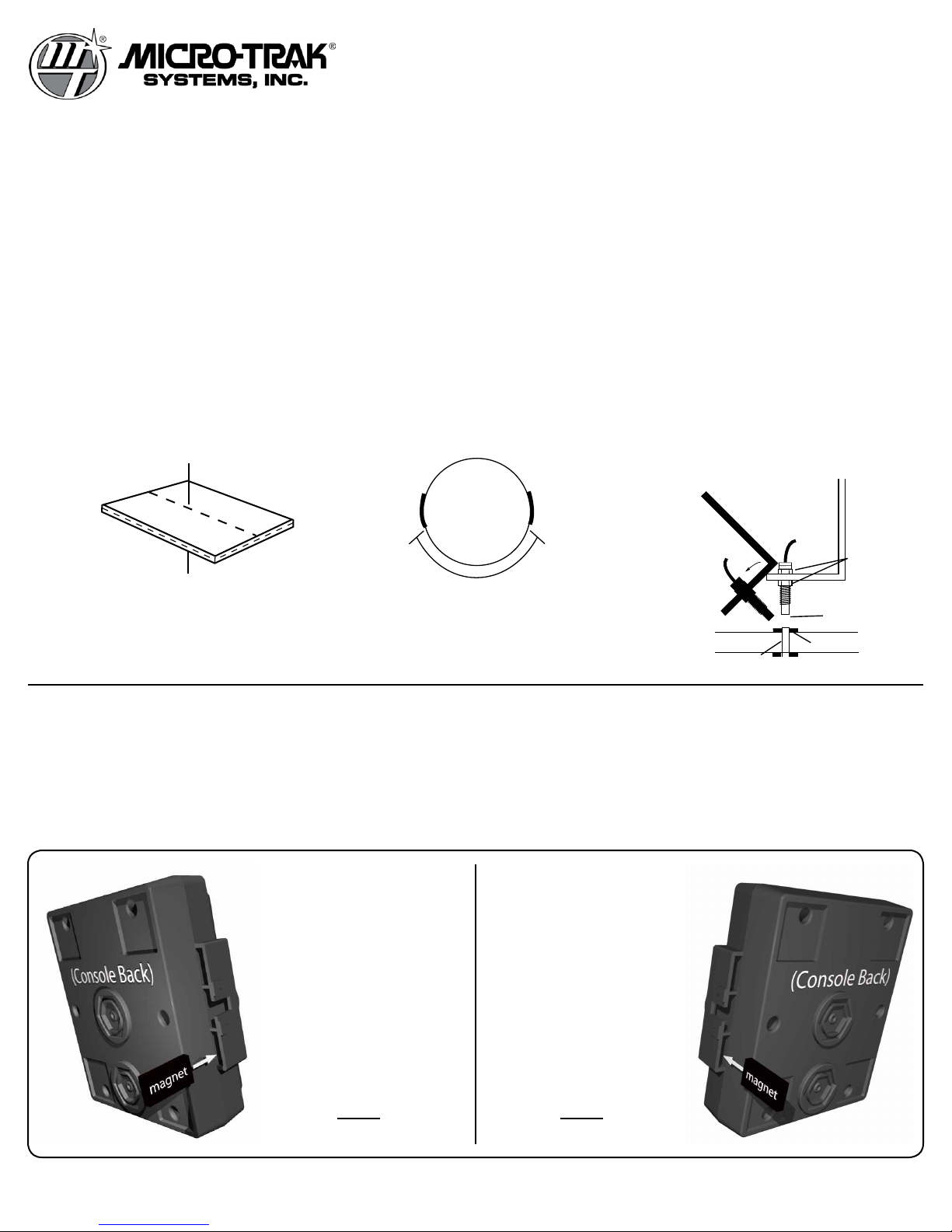
CONSOLE: Make sure the console is in the desired mode (Shaft
or Bin). Either set of 3 inputs (1-3 or 4-6) can be operated in either
SHAFT mode or BIN mode by inserting or removing magnets as
shown on page 2.
It is easy to tell which mode each set of inputs is operating in
when the console is turned on: if a set of inputs is set up for BIN
mode and all sensors are disconnected, all of the GREEN lights will
light. If set up for SHAFT mode, and all sensors are disconnected,
all of the RED lights will flash.
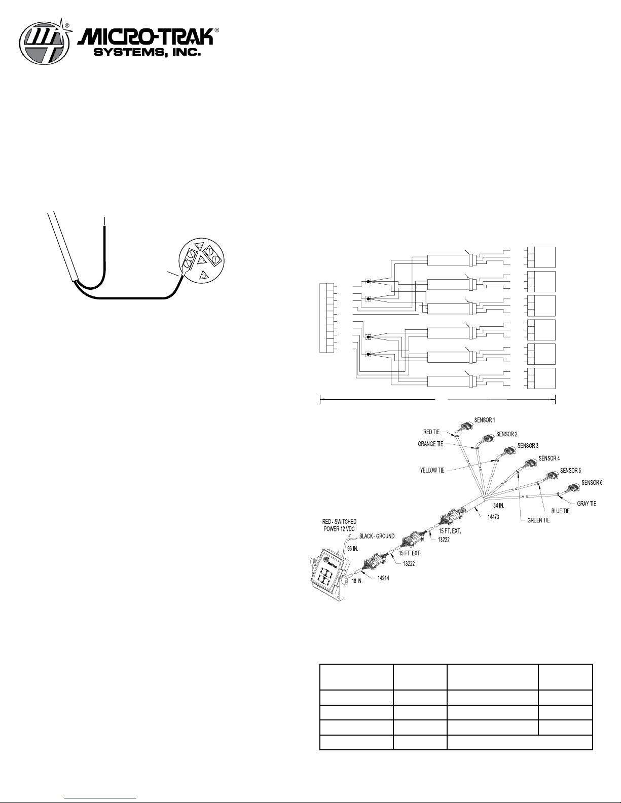
HARNESS: The harness can be checked using an ohmmeter or
continuity tester. The main wiring diagram shows the pin out of all
connectors.
ELECTRICAL INTERFERENCE: Erratic operation of the system
may be the result of electrical interference from ignition wires or
inductive loads (electrical clutch, fan solenoid, etc.) Always try to
route wires as far away from suspect areas as possible. If problems
occur, you may need to relocate the console and/or wiring harness,
or install a noise suppressor.
POWER: Check power source with a test light. If there is no power,
trace cable toward battery looking for breaks. Also check any fuses
or circuit breakers that supply power to the console.
ACCESSORY POWER: The shaft/bin cables have an accessory
power wire. Check for 12 volts between B (white) and C (black) of
the 3 pin connectors. If power is not present, make sure the ac-
cessory power wire is not open or shorted to ground or to another
wire. If this wire has a problem the console may exhibit erratic
behavior or not function at all.
SHAFT SENSORS: Improper connection or voltage could dam-
age sensors. The Micro-Trak standard sensor (black housing)
works similar to a reed switch, but requires power in order to
function. The internal circuit “closes” when near the south pole
(dashed side) of a magnet and is otherwise “open”.
Ground pin C (black) and connect 12 volts to pin B (white) of the
sensor cable. Connect the positive lead (red) of an ohmmeter or
continuity tester to pin A (red) and the negative lead (black) of the
ohmmeter or continuity tester to pin C (black) of the sensor cable.
Holding the tip of the sensor up to the south pole (dashed side) of
a magnet should result in a very low resistance (around 300 ohms).
Taking the sensor away from the magnet should result in a very
high resistance (infinite).
This troubleshooting procedure can also be used for the Micro-
Trak gear tooth sensor (red housing) with the following change;
use a piece of ferrous metal, like a screwdriver tip, to test the sen-
sor. It has an internal magnet to activate the sensing circuit.
Installation and Operation Instructions
Shaft-Trak TM -P/N 50209 (cont)
Copyright © 2019 Micro-Trak Systems • P/N 50209 • 021519
BIN LEVEL SENSORS: Ground pin C (black) and connect clean
12 volts to pin B (green) of the sensor cable. Connect the positive
lead (red) of an ohmmeter or continuity tester to pin A (red) and the
negative lead (black) of the ohmmeter or continuity tester to pin C of
the bin level sensor cable.
If the Bin Level Sensor is “blocked”, the output will show high
(infinite) resistance, and if the sensor is “unblocked” the result will
be low (300-500 ohm) resistance. Make sure the back of the sensor
is covered by the black foam pad; if light enters from the back of
the sensor, it will not “see” blockage. Use your hand or other solid
object to block both “eyes” on the sensor and the resistance should
go high.
CONSOLE INPUTS: If there is no response from any of the follow-
ing tests, refer to the main wiring diagram on the previous page to
locate the next connector in line toward the console and repeat the
test at that connector. If there is a response at that connector, the
problem may be in the cable between the two connectors (or the
connectors themselves).
SHAFT INPUT: Disconnect the shaft sensor from the extension
harness. Check for 12 volts between pins B (white) and C (black) of
the extension harness. Using a clip lead or other jumper wire (such
as a per clip bent in a “U”), rapidly short together pins A (red) and C
(black) of the 3-pin connector. The corresponding green light on the
console should light.
BIN INPUT: Disconnect the bin sensor from the main harness. The
corresponding green light on the console will light. Check for 12
volts between pins B (white) and C (black) of the sensor cable being
tested. Using a clip lead or other jumper wire (paper clip bent in a
“U”), short together pins A (red) and C (black) of the 3- pin connector.
The green light will turn off and the corresponding red light will flash
for one minute or until the short is removed.
REPLACEMENT PARTS LIST FOR SHAFTTRAK
Part Number Description
01544 Bin Level Sensor Kit
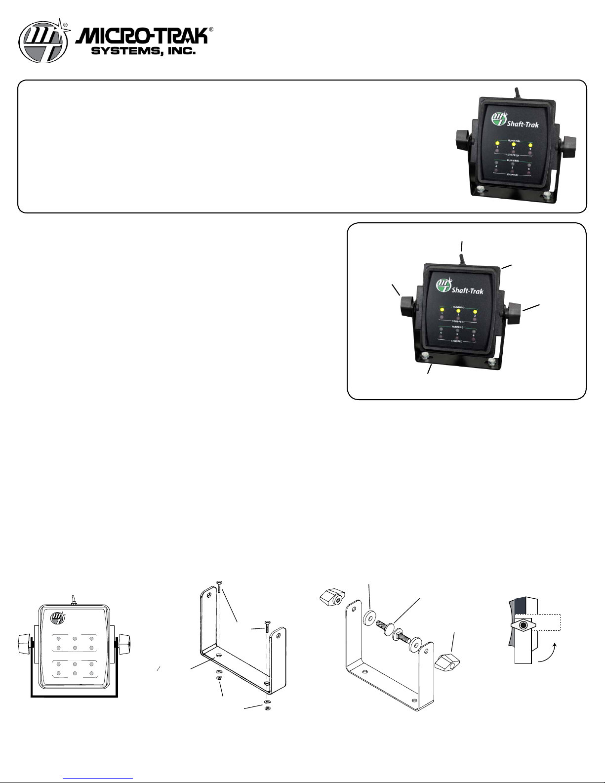
13181 Console Mount Kit, Base
13221 Cable, 10’ 10-pin M/P (optional)
13222 Cable, 15’ 10-pin M/P (2)
13223 Cable, 20’ 10-Pin M/P (optional)
13224 Cable, 25’ 10-pin M/P (optional)
13205 Cable, 5’ 3-pin M/P Extension (optional)
13206 Cable, 10’ 3-pin M/P Extension (optional)
13207 Cable, 15’ 3-pin M/P Extension (optional)
13208 Cable, 20’ 3-pin M/P Extension (optional)
14381 Console, Shaft-Trak Standard
14471 Molded Shaft Sensor w/ 5’ cable
14473 Shaft-Trak 6-sensor Branch Cable, 7’