ALLPRO Imaging ScanX 12 SE User manual

ScanX 12 SE
Digital Imaging System
Instruction Manual

ALLPRO Imaging
Page
2
12 SE
Section Page
Congratulations ............................................. 2
Purpose of this Manual ........................................ 3
General Safety .............................................. 3
Unpacking and Inspection . . . . . . . . . . . . . . . . . . . . . . . . . . . . . . . . . . . . . . 6
If You Need Assistance ........................................ 6
Important Information ........................................ 7
System Description ........................................... 8
Technical Data .............................................. 9
Computer System Requirements ..................................10
Abbreviations...............................................11
System Setup ...............................................12
Controls and Indicators ........................................14
Plate Care and Preparation .....................................15
Imaging Procedure ...........................................17
Plate Erasing Options .........................................19
Troubleshooting .............................................20
Accessories . . . . . . . . . . . . . . . . . . . . . . . . . . . . . . . . . . . . . . . . . . . . . . . . 22
Maintenance ...............................................23
Scheduled Maintenance........................................23
Warranty .................................................24
On-Line Warranty Registration ...................................24
Warranty Extension ..........................................24
TABLE OF CONTENTS
Congratulations on your purchase of ScanX 12 SE, the latest Digital Imaging System from ALLPRO
Imaging, a leading manufacturer of equipment for the podiatry professional since 1986. The ScanX 12 SE
processes Phosphor Storage Plates (PSPs) and has been designed and manufactured using state-of-the-art
technology to give many years of dependable service.
This manual covers the installation, operation and maintenance of ScanX 12 SE Digital Imaging System,
part number F3800. The ScanX 12 SE is hereafter referred to as ScanX in this manual. Review and
follow the guidelines included in this manual to ensure that your ScanX gives the highest level of service.
For product support and information on the ScanX, contact your authorized ALLPRO dealer; call our
Technical Support at 1-888-862-4050 or visit the web site, www.allproimaging.com.
Refer to the following companion documents as necessary:
Document Part Number
Imaging Plate Intensifier Screen Warning Instructions 73020
Phosphor Storage Plate Instruction Sheet 73474
CONGRATULATIONS

Page
3ALLPRO Imaging
12 SE
ScanX has been designed to minimize exposure of personnel to hazards. While the equipment is designed for
safe operation, certain precautions must be observed. Use of ScanX not in conformance with the instructions
specified in this manual may result in permanent failure of the unit.
General.
• Check with your dealer for packing material requirements if it is necessary to return the product to
the manufacturer. Correct packing guarantees optimal safety of the device during transport. Should it
become necessary to return the device to the manufacturer during the warranty period or other times,
the manufacturer will not accept claims for damage arising from using incorrect packing materials.
• Before every use, the operator must check the functional safety and the condition of the device.
• The operator must be knowledgeable in the operation of the device.
Use of Accessory Equipment.
The use of ACCESSORY equipment not complying with the equivalent safety requirements of this
equipment may lead to a reduced level of safety of the resulting system.
Use of ACCESSORIES or cables other than those specified or provided by the manufacturer may result
in increased EMISSIONS or decreased IMMUNITY of the EQUIPMENT.
Do Not Attempt Internal Service.
The interior of each component of ScanX is only accessible by removing hardware with special tools
and should only be opened and serviced by an authorized dealer service technician.
Contact your local Air Techniques authorized dealer for service. Failure to heed this directive may result in
equipment damage and voids the warranty.
Electrical Safety Notes.
The power line cord is the mains power disconnect device.
Use only the line cord and power supply provided with the unit.
Use only grounded electrical connections.
To avoid risk of electric shock, fire, short-circuit or dangerous emissions, never insert
any metallic object into the equipment.
Only use connection cable(s) delivered with the device.
Check the device cables for possible damage before switching on. Damaged cables, plugs
and sockets must be replaced before use.
Never touch open supply outlets and patients simultaneously.
Do not locate unit where it could be sprayed with water, or in a damp environment.
GENERAL SAFETY
This document is a guide to the proper use of ScanX. It provides the information necessary for the setup,
operation and routine care and maintenance of the device. Review and follow the guidelines included in
this Instruction Manual to ensure that your ScanX gives you the highest level of performance.
This manual is not to be used as a replacement for training in radiography.
For information regarding the computer system and imaging software, refer to the appropriate
documentation provided with your computer hardware and software.
PURPOSE OF THIS MANUAL

ALLPRO Imaging
Page
4
12 SE
Knowledge of Warnings and Cautions.
Users must exercise every precaution to ensure personnel safety, and be familiar with the warnings and
cautions presented throughout this manual and summarized below. In this manual, the following
definitions apply for all WARNING and CAUTION Statements:
WARNING: Any operation, procedure or practice, which, if not strictly observed, may result
in injury or long-term health hazards to personnel.
CAUTION: Any operation, procedure or practice, which, if not strictly observed, may result
in destruction of equipment or loss of effectiveness or damage to equipment
and Phosphor Storage Plates (PSPs).
DANGER: Opening ScanX by removing any covers or components makes the equipment
into a Class III b Laser Product. [Class 3B Laser Product (IEC 60825)].
Warnings -
Only trained professionals should use this device. Federal law prohibits the sale of this device
to individuals other than trained professionals. Use of this device, other than as described in this
manual, may result in injury.
ScanX contains a laser and is a Class 1 [Class 1 (IEC 60825)] Laser Product. Use of controls or
adjustments or performance of procedures other than those specified herein may result in hazardous
radiation exposure. The laser is on only during an active scan.
Only a trained technician from an authorized dealer should remove a cover from the ScanX.
Direct eye contact with the output beam from the laser may cause serious damage and possible blindness.
Equipment Lifting. ScanX weighs 57 pounds or more and two people may be required to prevent
injury when lifting.
Do not open the equipment to maintain it. ScanX contains no internal user serviceable parts. If
there is a service problem, contact your authorized dealer.
Operate ScanX in dry environment. To prevent fire or electrical shock, do not expose this appliance
to rain or moisture.
Equipment Disposal. Disposal of ScanX units, including internal batteries, electronic circuitry and
PSPs must be accomplished only at the appropriate facilities for recovery and recycling. Make sure to
dispose of such items in accordance with current federal, national, state and local government rules
and regulations.
Cautions -
EMC Compliance Requirements.Use USB cables not exceeding 3m to connect between the com-
puter and the scanner. Cable lengths greater than 3m may violate EMC compliance.
Stacking or using the scanner adjacent to other equipment may violate EMC compliance and interfere
with the scanner operation.
Do not use damaged Phosphor Storage Plates (PSPs). Damaged PSPs may not provide reliable
diagnostic images.
GENERAL SAFETY

Page
5ALLPRO Imaging
12 SE
Markings.
The following terms or symbols are used on the equipment or in this manual to denote information of
special importance:
Cautions (Continued)-
Completely clean and erase PSPs before taking an X-ray exposure. See the PLATE PREPARATION
section of this manual.
Minimize exposing an X-ray exposed PSP to light. Transfer the PSP into the inlet slot quickly to
minimize exposure to light.
Use care in handling PSPs - Avoid fingerprints and scratching. Refer to the instructions provided
with the PSP package for further information on handling. Make sure to use plate protectors.
Use of other manufacturer’s imaging plates. Do not put PSPs designed for drum-type or other
scanners in the ScanX. The hooks and/or frames on the ends or around these PSPs, or PSPs of different
thickness (especially thicker ones) will damage the ScanX.
Contraindications. None known.
GENERAL SAFETY
DANGER
AVOID DIRECT
EXPOSURE TO BEAM
LASER RADIATION WHEN OPEN
CAUTION
CLASS 1 LASER PRODUCT
CLASS 3B LASER
RADIATION WHEN OPEN
AVOID EXPOSURE TO BEAM
CLASS IIIb LASER PRODUCT
COVER REMOVED MAKES
THIS DEVICE A
ScanX is a Class I Laser Product [Class 1 Laser Product (IEC)]
This warning label identifies ScanX as such a product and describes
the potential danger to humans in the event the product is opened during
service. There is no laser radiation from this product when operated and
maintained as instructed.
The Laser Product Accession Number is 0212282-00
Alerts users to important Operating and
Maintenance instructions. Read carefully
to avoid any problems.
Indicates date
of manufacture
Identifies the
name of the
manufacturer.
Warns users that uninsulated voltage
within the unit may be of sufficient
magnitude to cause electric shock.
Indicates that the unit conforms with
WEEE Directive 2002/96/EC and must be
disposed of only at the appropriate facilities
for recovery and recycling.
Manufacturer:
Air Techniques, Inc.
1295 Walt Whitman Road
Melville, New York 11747 USA
Medical Device Safety Service
Schiffgraben 41
30175 Hannover, Germany
EC REP Indicates item used only
once. Discard after use.
2
Indicates the
ScanX is a UL
Listed product.
LABORATORY
EQUIPMENT
60CB
E234737
Indicates that ScanX complies with the
Medical Device Directive 93/42/EEC.

ALLPRO Imaging
Page
6
12 SE
UNPACKING & INSPECTION
System Components
Main Assembly
24 VDC Power Supply Adapter
10-Foot Power Cord
6-Foot 2.0 USB Cable
Accessory Kit containing:
Exit side Plate Supports (Qty 2)
ScanX Cleaning Sheet Sample
Dust Cover
User Information Folder containing:
ScanX Quick Start Guide
CD Disk containing Drivers, Utilities
and Operator’s Manual
ScanX Tutorial Digital Video
PSP Cleaning Wipe Sample Pack
Warning: ScanX weighs 57 pounds or more and two people may be required to prevent injury when lifting.
IF YOU NEED ASSISTANCE
ALLPRO ScanX systems are designed and manufactured to high standards. They are easy to install and
use and typically deliver high-quality performance. If any difficulties are encountered with this product,
please contact your authorized ALLPRO dealer, Technical Support at 1-888-862-4050 or visit our web
site, www.allproimaging.com.
Unpacking
Unpack each component of ScanX and inspect for physical damage such as scratched panels, damaged
connectors, etc. If there is any damage, notify your ALLPRO authorized dealer immediately so corrective
action can be taken. Save all cartons and packing materials to protect ScanX in the event that it is to be
transported or shipped in the future. ScanX consists of the indicated main assembly and accessory kit as
listed below. Verify that all listed items were received. If any item is missing, notify your dealer.
Included System Components
ScanX consists of the indicated main assembly and accessory kit as listed below: (See the Technical
Data section for ratings and identification for specific models.)

Page
7ALLPRO Imaging
12 SE
General Notes.
All instructions in this manual form an integral part of the unit. They must be kept close to
the unit and in readiness whenever required. Precise observance of these instructions is a
pre-condition for use of the unit for the intended purpose and for its correct operation. This
manual should be passed on to any future purchaser or operator.
Safety of the operator as well as trouble-free operation of the unit are only ensured if use is
made of original equipment parts. Moreover, use may only be made of those accessories
that are specified in the technical documentation or that have been expressly approved and
released by the manufacturer for the intended purpose. The manufacturer cannot warranty for
the safety or proper functioning of this unit in the case where parts or accessories are used that
are not supplied by the manufacturer.
There is no guarantee against damage arising where parts or accessories are used that are not
supplied by the manufacturer.
Observe the usage and storage conditions.
Appliances which accumulate condensation or become wet through a change of temperature may only
be operated after they are fully dry again.
The manufacturer regard themselves as being responsible for the equipment with regard to safety,
reliability and proper functioning only if assembly, resetting, changes or modifications and
repairs have been carried out by an authorized dealer and if the equipment is used in conformity
with the instructions contained in this manual.
The device conforms to the relevant safety standards valid at this time.
Correct Usage
Operation of ScanX may only be carried out by suitably qualified personnel.
ScanX is only to be used in the processing of exposed PSPs.
If the device is stored in a cool environment and brought to a warmer one, condensation
can build up. Do not connect the device until it has warmed up to room temperature and is
absolutely dry.
The immediate working area should be free of all possible interferences (e.g. strong magnetic
fields), as these could affect the operation.
ScanX may only be operated together with authorized software.
Correct usage includes observing all adherence to the set-up, operation and maintenance
instructions.
Any use, above and beyond that described in this manual as correct usage, will invalidate the
warranty.
Incorrect Usage
Any use that is not described in this manual as correct usage is considered as incorrect usage. The
manufacturer is not to be held liable for any damage caused as a result of incorrect usage. The
operator bears all risks.
IMPORTANT INFORMATION
ALLPRO Imaging
Page
8
12 SE
General
ScanX is a self-contained digital imaging scanner/eraser system that utilizes reusable photostimulable
or Phosphor Storage Plates (PSP) in place of X-ray film to produce quality digital radiographs. The PSPs
are durable and reusable thousands of times. Upon exposure to X-rays, the plate stores a latent image,
which is scanned by the ScanX. After scanning, the image is processed via the user-supplied computer
running authorized software and ready for viewing in seconds. In addition to immediate display of the
resultant images, the software allows image enhancement processing, storage (hard drive or CD), and
sharing/retrieval.
An additional feature of ScanX includes a patented in-line plate erase function that removes the latent
image from the plate immediately after scanning. This design provides an efficient one-operation scanning
and erasing process leaving the user with a PSP ready for the next X-ray procedure.
Features
High resolution digital images in seconds.
Share results anywhere, anytime.
Lightweight extruded aluminum frame resists dents.
Patented, built-in eraser with manual or auto erase function.
Works with a wide range of X-ray sources including gamma ray.
Adjustable settings for optimum dynamic range.
Sturdy, isolating/damping feet eliminate potential image quality issues due to vibration.
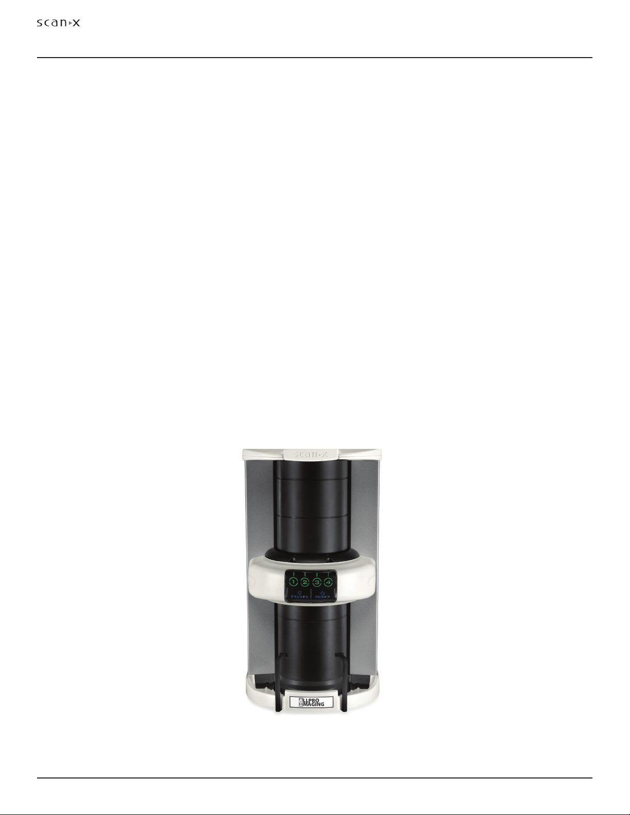
SYSTEM DESCRIPTION
Figure 1. ScanX 12 SE Digital Imaging System, P/N F3800

Page
9ALLPRO Imaging
12 SE
Electrical Requirements:
Supply Voltage: Universal: 100V to 240V (90V to 264V) 50/60 Hz
Supply Current: 1.2 A Maximum
Line Cord: North American style 10 foot long Hospital Grade power cord,
P/N 73096. Country specific line cords are available
Power Supply: 24 Volt Power Supply, P/N B7095 provided
Physical Properties:
Dimensions
Depth: 15.5 inches (39.4 cm)
Width: 15.5 inches (39.4 cm)
Height: 28.5 inches (72.4 cm)
Weight: 57 pounds (26 kg)
Environmental Conditions:
Unit in Operation
Temperature: 50°F to 105°F (10°C to 40°C)
Humidity: 10 to 80% (Non-condensing)
Storage and Transport
Temperature: -21°F to 130°F (-29°C to 54°C)
Humidity: 10 to 80% (Non-condensing)
Note: Resolution of the device is dependent on operating mode and specific imaging
plate type used.
Resolution:
Horizontal: 5.0 LP/mm
Vertical: 5.0 LP/mm
Compliance Data:
Laser Classification: Class I Laser Product Compliance with
FDA HHS 21 CFR 1040.10 and IEC 60825-1
Laser Product Report
Accession Number: 0212282-00
Classification:
Class 1, No Applied Parts, Transportable, Continuous Operation,
Equipment not suitable for use in the presence of flammable anaesthetic mixture(s).
Electromagnetic Interference:
Electromagnetic interference between the equipment and other devices can occur. Do not use the
equipment in close conjunction with sensitive devices, or devices creating high electromagnetic
disturbances.
TECHNICAL DATA

ALLPRO Imaging
Page
10
12 SE
IMPORTANT: To operate ScanX, it must be connected to a compliant Computer System supplied
by the customer. In addition, authorized Imaging Software, purchased from
your dealer or other company, must be installed on the computer in order to
operate ScanX.
Computer System Required Components
The minimum computer system, computer and monitor, requirements necessary to operate ScanX are
listed below.
Operating System: Windows XP Professional with Service Pack 3 or later for an Intel
32-bit processor;
Microsoft Windows XP Professional 64-bit Edition with Service Pack 2
or later for an Intel 64-bit extended (x64) processor;
Microsoft Windows Vista Business, Enterprise, or Ultimate with Service
Pack 2 or later for an Intel 32-bit or an Intel 64-bit extended (x64)
processor;
Microsoft Windows 7 Professional, Enterprise, or Ultimate with
Service Pack 1 for an Intel 32-bit or an Intel 64-bit extended (x64)
processor; or
Microsoft Windows 8.1 Professional or Enterprise for an Intel 32-bit
or an Intel 64-bit extended (x64) processor.
USB Port/Version: USB 2.0 or later
Hard Drive: 200 MB available disk space required to start scanning.
Image Management Compatible authorized third-party software
Software: (not included with product).
Optical Drive: Device capable of reading a CD-ROM required
Recommended Components
The items listed below are recommended (but not required) computer system components to aide in
ScanX operation
System RAM: 2 GB
CPU/Speed: Pentium-4, 2 GHz or higher
Hard Drive: 500 GB
Monitor SVGA 24”, 1280x1024 or higher resolution, contrast ratio
10,000:1, .22 dot pitch
Video Display Adapter: 32 MB RAM
Peripherals: Standard Keyboard & Mouse
Backup Device
External Surge Protector
Power supply backup
TABLE OF CONTENTSCOMPUTER SYSTEM REQUIREMENTS
Page
11ALLPRO Imaging
12 SE
TABLE OF CONTENTSCOMPUTER SYSTEM REQUIREMENTS
Abbreviations used in this manual are summarized below.
A ampere(s)
AC alternating current
CD-ROM compact disk, read-only memory
CFR Code of Federal Regulations
CPU central processing unit (your computer)
cm centimeter
GB gigabyte (230 109bytes)
GHz Gigahertz (109of Hertz)
H height
Hz Hertz (cycles per second)
IEC International Electro-technical
Commission
IMS Image Management Software
IP imaging plate
LED Light emitting diode
L length
lbs pounds
lp/mm line pair per mm
lux a measure of light intensity
lux a measure of light intensity
MB megabytes (220 106bytes)
mm millimeter (10-3 m)
MONTH YYYY date (Month, 4 digit year)
Phosphor a luminescent material
P/N or PN part number
PSP photostimulable storage
phosphor plate
(imaging plate)
RAM random access memory
RH relative humidity
SVGA Super Video Graphics Array
USB Universal Serial Bus
UL Underwriters Laboratories
V Volts
W Watts, width
°C degree Celsius
°F degree Fahrenheit
in. inch
ABBREVIATIONS
Control Panel Home
Device Manager
Remote settings
Advanced system settings
Control Panel > All Control Panel Items > System
System protection
View basic information about your computer
Service Pack 1
Copyright 2009 Microsoft Corporation. All rights reserved
©
Windows 7 Professional
Windows edition
System
Processor:
Rating:
Intel(R) Core(TM)2 Quad CPU Q6600 @2.40GHz 2.39 GHz
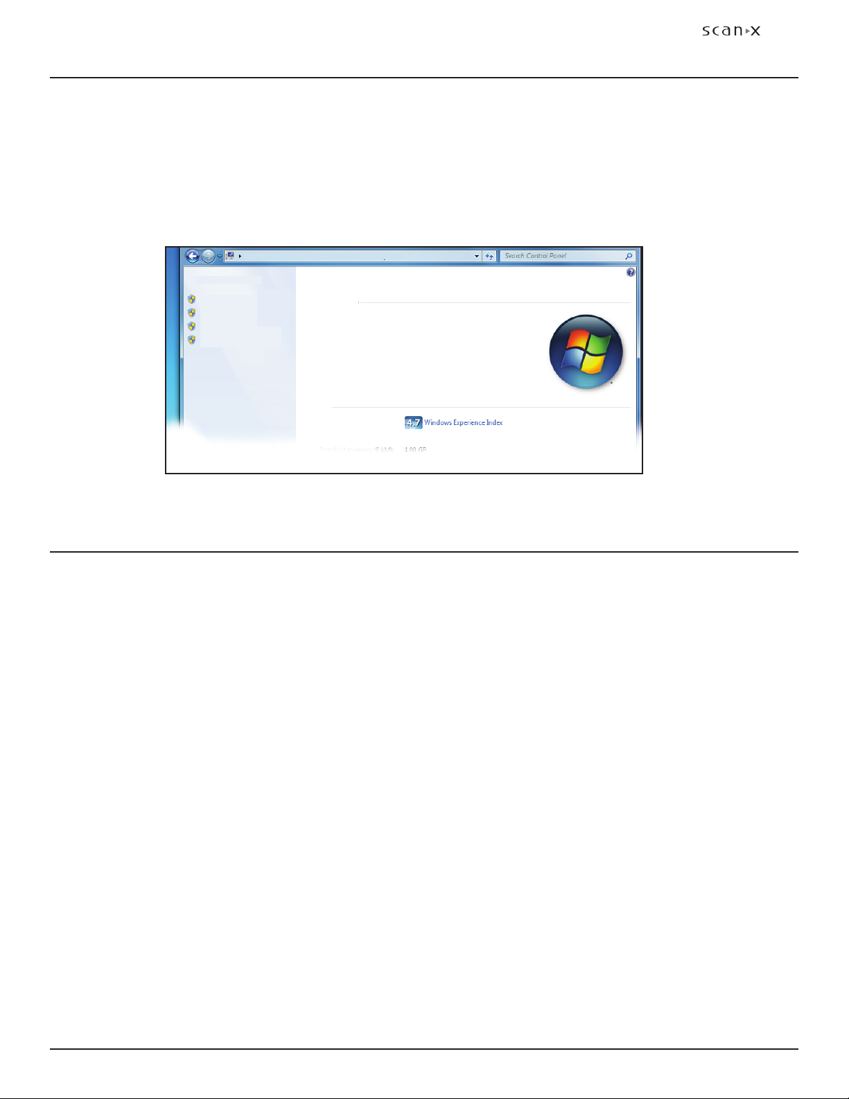
System Properties.
If unsure of the operating system version installed, check that it meets the necessary requirements by
checking the System Settings window as shown below.
The System Settings window can also be opened from the Control Panel button. Just press the Start
button and select Control Panel and then click the System icon.

ALLPRO Imaging
Page
12
12 SE
SYSTEM SETUP
IMPORTANT: ScanX is designed to be installed by your authorized dealer. The user must
provide appropriate and compliant computer hardware. In addition, authorized
Imaging Software purchased from your dealer or other company, must be
installed on the computer in order to operate ScanX.
Site Selection
ScanX may be located almost anywhere in the office. Follow these guidelines for optimum performance:
Lighting conditions: Set up the scanner in ordinary room light, however, direct sunlight and light fixture(s)
above and near ScanX producing more than 400 lux of light at the PSP inlet must be avoided.
Provide a stable, flat counter top large enough to hold the scanner, plus provide a working area
for resting and opening cassettes.
Locate the computer within 6 feet from unit.
Access to a hospital grade grounded electric Mains AC outlet using the line cord and power supply
adapter provided, must be within line cord length.
Device Driver Installation
Before connecting ScanX to your computer or attempting to use it for the first time, run the Setup program
on the Drivers and Utilities Disk. This CD contains the necessary device drivers to communicate with the
imaging software installed on the user’s computer. Normally, this program runs automatically when the
CD is inserted into the drive for the first time. If not, run the Setup program located in the root directory
of the CD (typically D:\Autorun.exe).
ScanX Connection Procedure
Refer to Figure 2 and perform the following procedure to connect ScanX for operation to a computer
for the first time.
1. Select a location that meets the Site Selection guidelines.
2. Make sure that the computer meets all requirements (see page 10) necessary to support ScanX
operation. Set up the computer according to the manufacturer's recommendations.
3. Verify that an authorized Imaging Software and the supplied USB drivers are installed properly
on the computer.
4. Connect the high speed USB cable between the USB Type B connector located on ScanX rear
panel and the USB Type A connector located on the computer.
Note: Connect the 24V Power Supply Adapter to ScanX prior to plugging the line
cord into the Mains outlet.
5. Connect the 24V Power Supply Adapter Output Connection Cable to the Inlet Power Jack located
on ScanX rear panel.
6. Connect the line cord between the Mains outlet and the 24V Power Supply Adapter. The scanner
is now in the Standby mode.
7. Switch ScanX from standby to ON by pressing the push button POWER switch ( ) located on
the Control Panel on the front of the scanner. Verify that both the blue LED indicators, for
the READY and ERASER switches, respectively illuminate.
8. With both ScanX and computer turned on, Windows detects ScanX as a new USB Device and
the Found New Hardware Wizard will appear.
Windows should automatically find the drivers installed from ScanX Drivers and Utilities Disk.

Page
13ALLPRO Imaging
12 SE
SYSTEM SETUP
Figure 2. ScanX Power and Computer Connections
Exit Side Plate Supports Installation
The supports are used to catch the PSP after processing. Refer to Details C and D below and install the
supports as follows.
CAUTION: ScanX weighs 57 pounds. Two people may be required to perform this
installation to prevent damage to the unit.
1. Carefully tilt the ScanX back enabling access to the slots under of the ScanX.
2. Align the two quick connect clips of each support with the corresponding slots.
3. Insert each support into the slots until a click is heard.
4. Return the ScanX to the upright position on the installation site counter top.
Detail B
Type B USB
Connector
Type A USB
Connector to
Computer
TO
POWER
SUPPLY
Power
Supply
Note: The power line cord is the
Mains disconnect device.
Line Cord
Type B USB
Receptacle
Inlet Power
Jack
ScanX
Side
Quick
Connect Clips
Slots
Detail C
ScanX
Underside
ScanX Power and Computer
Receptacles Located on Right Rear Panel
Power Supply
Line
Cord
Detail A
Align Clips
& Slots
Detail D
Snap
Supports in
Place
To ScanX
Inlet
Power
Jack

ALLPRO Imaging
Page
14
12 SE
CONTROLS & INDICATORS
Control Switch and Indicator Functions
Item Function
POWER Switch
Toggles between the Standby and Ready mode as follows:
1. Press to switch from the Standby mode to the Ready mode.
2. Press and hold down for at least 2 seconds to switch to the Standby mode
from the Ready mode.
POWER Status LED
Indicator
Displays the device status as set by the POWER Switch:
1. Illuminates dim amber to indicate that ScanX is the Standby mode of
operation.
2. Illuminates bright blue to indicate that ScanX is the Ready mode of operation.
3. When extinguished, it indicates that AC MAINS are interrupted and no
operating power is present.
ERASER Switch
Note: The switch has no effect once the plate
scanning operation begins.
Enables or disables the erase function operation:
1. Press and hold for 2seconds to disable the erase function completely.
2. Press and hold for 2seconds a second time to enable the erase function.
ERASER Blue Status
LED Indicator
Displays the erase function status as set by the ERASER Switch:
1. Extinguished when the AC MAINS are interrupted. No power.
2. Extinguished when the system is set to the Standby mode
3. Illuminated bright blue when the In-Line Erase function is enabled.
(Default mode has eraser enabled.)
4. Flashes when the In-Line Erase is disabled.
Numeric Lane Indicator
with Visual Pointer LED
Indicators
(Bi-Color LEDs)
Displays the operational status of each scanner lane:
1. Extinguished when the AC MAINS are interrupted. No power.
2. Extinguished when the system is set to the Standby mode.
3. Extinguished when ScanX is not activated by imaging software on the host
computer. (Imaging software not set to acquire images.)
4. Illuminates bright green when activated by imaging software denoting that
the imaging software is set to acquire images and the corresponding lane is
ready to process a PSP plate.
5. Illuminates amber while the corresponding lane is busy processing.
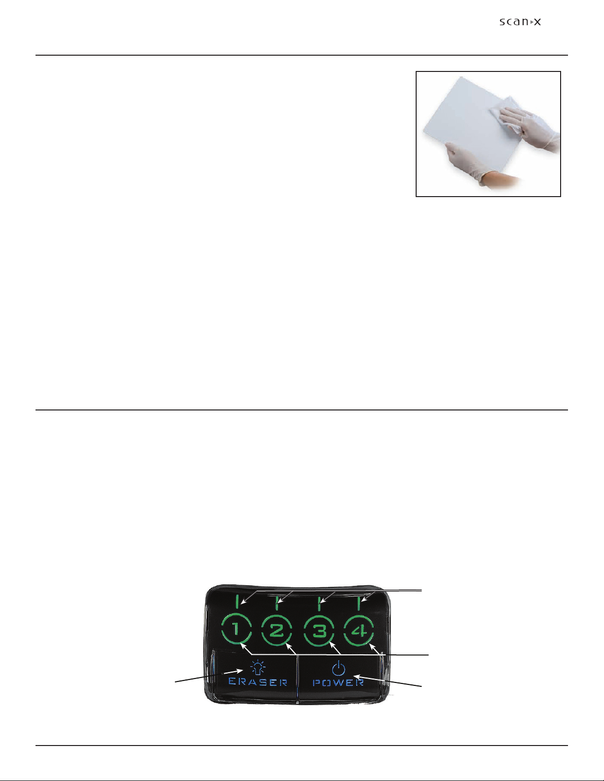
Figure 3. Front Panel Control and Indicator Locations
POWER
Switch / Status LED
Indicator (blue / amber)
ERASER
Switch / Status LED
Indicator
Numeric Lane
LED Indicators
(green / amber)
Visual Pointer
LED Indicators
(green / amber)

Page
15ALLPRO Imaging
12 SE
PLATE CARE & PREPARATION
Note: Wearing disposable gloves is optional when handling PSPs.
Prior to performing the imaging procedure provided on the following pages, the user must be familiar
with the care, handling and preparation of the PSP in order to ensure successful image scanning. Figure 5
shows a typical extraoral plate.
Black Side or
Back of PSP
White or Sensitive Side
or Front of PSP
Figure 5. Typical Extraoral Plate Configuration
IMPORTANT: Never power down or remove power from ScanX during a scanning session.
Figure 4. READY Mode Front Panel Indicators
READY Mode of Operation
ScanX is designed to be left on continuously in the READY mode, during the active day. When ScanX is
set in this mode of operation, the POWER and ERASER Status LED Indicators illuminate bright blue as
shown by Figure 4. The Numeric Lane Indicator with Visual Pointer LED Indicators are not lit.
STANDBY Mode of Operation
At the end of the day, or whenever desired, power down ScanX simply by pressing and holding the
POWER switch for approximately two seconds, until the ERASER and POWER LED Indicators extinguish.
The Status LED READY Indicator illuminates dim amber indicating that ScanX is set to the STANDBY
mode of operation.
MAINS Disconnect
The power line cord is the Mains disconnect device. All front panel indicators extinguish when the AC
MAINS are interrupted when the line cord is disconnected or the main facility power circuit fails.
CONTROLS & INDICATORS
POWER
Switch / Status LED
Indicator Illuminated
Blue
ERASER
Switch / Status LED
Indicator Illuminated
Blue
Visual Pointer & Numeric
Lane LED Indicators
Extinguished

ALLPRO Imaging
Page
16
12 SE
Handle PSPs with Care.
Do not crease PSPs.
Avoid scratching or soiling PSPs.
Do not store PSPs in a hot or moist area.
Protect the PSPs from direct sunlight and ultraviolet rays.
Pick up the PSPs using two fingers around the edges to avoid unnecessary contact with the plates.
Plate Protection
When storing or transferring extraoral size PSPs use an X-ray Cassette for PSPs so as not to scratch or
soil the sensitive surface or nick the edges.
Note: Cassettes must not contain intensifying screens when using PSPs.
X-ray Cassette. Place the PSP into the appropriate X-ray Cassette with the sensitive (front) side of the
PSP towards the Tube-side of the cassette and close cassette.
IMPORTANT: PSPs must always be erased prior to use.
Note: Use PSPs within 24 hours of last erasure. Repeat erasing process if PSPs
have been stored longer than 24 hours.
Erasing PSPs
Each PSP should be used (i.e. X-ray exposed and scanned) within 24 hours of erasure since natural
radiation will add noise to the PSP. Erase PSPs by simply using the In-Line Erase Feature. Erasing of PSPs
can be accomplished using one of the following methods.
Note: Both erasing methods will result in an erased PSP suitable for reuse. The user
will not observe any difference in ScanX operation when using either method.
Method #1
Perform the Activate Scanner and the Scanning and Erasing Plates procedures on pages 19 thru
21 for either intraoral or extraoral as necessary. Except when performing step 4 of the Activate
Scanner procedure, select the Erase option from the installed imaging software to activate ScanX.
This method does not scan the plate and no image will be acquired.
Method #2
Perform the Activate Scanner and the Scanning and Erasing Plates procedures on pages
19 thru 21 for either intraoral or extraoral as necessary. This method scans the plate and
then erases the plate. Using this method, the imaging software may acquire a “junk image”
(scanned latent plate image) that should be subsequently deleted from the imaging software.
PLATE CARE & PREPARATION
Page
17ALLPRO Imaging
12 SE
PLATE CARE & PREPARATION
Cleaning Phosphor Storage Plates
For the best images, PSPs should be handled carefully and kept clean.
Use specially formulated PSP Cleaning Wipes (P/N B8910) to clean all
PSPs. These single-use, extra soft, 100% polyester fabric wipes will not
scratch or damage while safely removing dust, hair, dirt and smudges
from the imaging surface. Use one wipe and clean plates as follows:
1. As shown by Figure 6, gently wipe the PSP Cleaning Wipe over the
dry Plate surface. Wipe back and forth and then in a circular motion.
2. Allow the plate surface to air dry. Make sure that the PSP is completely
dry before re-using.
Disinfecting the Phosphor Storage Plates
There is no reason to routinely disinfect the PSPs unless contamination is suspected. If a PSP has touched
a contaminated surface, it may be immersed briefly in a cold sterilant (such as a 2% Gluteraldehyde
solution) according to sterilant manufacturers directions. Do not immerse the plate if there is any
evidence of deep scratches in the surface of the plate or nicks in the edges of the plate. After disinfection,
clean and dry the plate using the instructions above.
Disposal of Phosphor Storage Plates
Consult with your federal, national, state and local government, for rules and regulations on disposal
of Phosphor Storage Plates.
Figure 6. PSP Cleaning
Activate Scanner. Activate ScanX by performing the following procedures.
1. Make sure the computer and ScanX are correctly connected as shown in Figure 2.
2. Switch the scanner from STANDBY to the READY mode by pressing the POWER switch.
3. Verify that the POWER and ERASER Status LED Indicators illuminate blue.
4. Activate the Scanner and select the desired image type and resolution via the imaging software.
5. Verify that the four Numeric Lane Indicators with Visual Pointer LED Indicators illuminate green as
shown by Figure 7 when the Scanner has been activated, indicating that the imaging software is set
to acquire images and PSPs can be fed into the corresponding lane Plate Guides.
Figure 7. Front Panel Indicators of Activated ScanX Set in the READY Mode
IMAGING PROCEDURE
POWER
Switch / Status LED
Indicator Illuminated
Blue
ERASER
Switch / Status LED
Indicator Illuminated
Blue
Numeric Lane
LED Indicators
(green / amber)
Visual Pointer
LED Indicators
(green / amber)

ALLPRO Imaging
Page
18
12 SE
IMAGING PROCEDURE
Figure 8. Feeding a Plate into the
ScanX 3800
IMPORTANT: The following procedures are not to be used as a replacement for training in radiography.
Only trained radiography professionals should perform X-ray procedures.
Note: Make sure to remove intensifying screen from the X-ray cassette when using
PSPs. Intensifying screens degrade images when using PSPs as X-ray media.
Plate X-ray Procedure. Put an image on a PSP as follows.
1. Place the erased PSP into the appropriate X-ray cassette, with the Tube side (sensitive side) of PSP
facing towards Tube side of cassette.
2. Load cassette into the exposure device as previously done for film, and follow the X-ray device
manufacturer’s instructions for PSP exposure.
3. Bring the cassette containing the exposed PSP to the ScanX. The PSP is now ready to be scanned
to read the image by performing the Imaging Procedures.
Activate Scanner. Activate ScanX by performing the following procedures.
1. Make sure the computer and ScanX are correctly connected as shown in Figure 2.
2. Switch the scanner from Standby to the Ready mode by pressing the POWER switch.
3. Verify that the POWER and ERASER Status LED Indicators illuminate blue.
4. Activate the Scanner and select the desired image type and resolution via the imaging software.
5. Verify that the four Numeric Lane Indicators with Visual Pointer LED Indicators illuminate green as
shown by Figure 7 when the Scanner has been activated, indicating that the imaging software is set
to acquire images and PSPs can be fed.
Note: Only one exposed PSP can be fed into the ScanX at a time. The next PSP may be fed only after all lane
indicator light LEDs change from amber to bright green.
Scanning and Erasing Plates. Scan and erase a PSP in one operation as follows.
1. Orient the cassette so that the Tube side is facing
down and the hinge is away from you.
2. Open the cassette and grasp the PSP by its ends
with your finger tips, and quickly (minimizing
exposure to ambient light) move it to the ScanX,
with Tube side of PSP towards the unit.
3. Position the plate against the curved surface and
gently slide the plate down (See Figure 8) until
the transport mechanism takes over and the
plate moves on its own.
4. At this point, the track lights will turn amber,
indicating the PSP has been sensed and the
ScanX is transporting the PSP.

Page
19ALLPRO Imaging
12 SE
IMPORTANT: PSPs will not be erased after scanning when operating ScanX with
the eraser disabled. PSPs must always be erased prior to exposure to
X-rays for new images.
Scanning Plates without Erasing
ScanX can be operated with the in-line eraser feature turned off. When the eraser mode is disabled, the
device scans the same as when the eraser is enabled except that the PSPs are not erased after scanning.
Scan an intraoral PSP without erasing the image as follows.
1. Activate the scanner by performing the procedures on previous page.
Note: Upon turn-on, ScanX defaults with the eraser mode enabled. This must be
disabled prior to scanning to prevent erasing of the scanned PSP.
2. Disable the eraser mode of operation by pressing and holding the membrane ERASER switch for 2seconds.
The ERASER switch is located on the Control Panel. See Figure 9.
3. Verify that the blue ERASER LED indicator flashes blue indicating that the Erase function is OFF.
PSPs will not be erased after scanning.
4. Insert the exposed PSPs to be scanned into the ScanX Plate Guides by performing the Scanning
and Erasing Plates procedures provided on the previous page. When the scanner is operating
with the eraser disabled, the exit slot will be unlit (no red glow).
5. The scanned PSPs still contain latent images that require erasure. Make sure to erase each PSP
prior to reuse for new images.
Figure 9. Front Panel Indicators of Activated ScanX Set in the READY Mode
Erase Only Mode
ScanX can be used to just erase PSPs. This is done simply by selecting the Erase option (instead of Scan)
from the installed authorized imaging software when activating the ScanX. During the Erase Only mode
just the in-line eraser is activated. The PSP is transported through the unit as a normal scan but is not
scanned. No image is acquired and the PSP is erased and ready for reuse as necessary. See Erasing
PSPs on page 16.
PLATE ERASING OPTIONS
Numeric Lane
LED Indicators
(green / amber)
Visual Pointer
LED Indicators
(green / amber)
Important: ERASER Indicator flashes
blue to alert that eraser is
disabled and PSPs will not
be erased after scanning.
POWER
Switch / Status LED
Indicator Illuminated
Blue
ERASER
Switch / Status LED
Indicator Illuminated
Blue

ALLPRO Imaging
Page
20
12 SE
TROUBLESHOOTING
Trouble Possible Cause Corrective Action
1No power No Amber
light on switch panel
• Not plugged in.
• No power at Mains Outlet
• Defective power supply
• Check the line cord connection is
firmly plugged in.
• Make sure outlet is grounded and has
power.
• Call your Air Techniques dealer.
2Blue, Amber or Green
indicator does not light.
• Defective light or circuitry. • Call your Air Techniques dealer.
3Image Management
Software does not rec-
ognize ScanX when
selected.
• Inadequate Computer System.
• ScanX has not been turned on.
• The computer connection cable
is loose or defective.
• The computer does not recognize
that ScanX is connected.
• ScanX hardware problem.
• Verify Computer requirements
(Page 10).
• Make sure that the POWER switch
is set to ON and the Blue indicator
light is lit.
• Reconnect the cable. Check for
tightness. Replace if necessary.
• Verify that the Setup program was
correctly installed (Page 12). Use
different USB port.
• Call your Air Techniques dealer.
4Plate does not scan
properly.
• The PSP was not pushed far
enough into ScanX.
• Fully feed the PSP into the Plate
Guide.
5No image appears
after scanning.
• The PSP fed backwards
(printed side towards ScanX).
• The PSP was erased prior to
scanning.
• X-ray source failed.
• Hardware failure.
• Quickly refeed the plate with the
printed side out. If Eraser mode
was enabled during scanning,
you may need to retake image.
• Feed the PSPs into the scanner
immediately and quickly after
removal from the Barrier Envelope.
• Call your X-ray service dealer.
• Call your Air Techniques dealer.
Important:
Do not allow the PSP to
be exposed to light between
taking an X-ray and scan-
ning with the ScanX.
Table of contents
Other ALLPRO Imaging All In One Printer manuals


