Allpro 400E User manual
P.O.BOX 8006, MOORPARK, CA. 93020-8006 FORM NO. 001- 455 MAR 99
SHIP TO: 5397 COMMERCE AVE. MOORPARK, CA. 93021 TEL: 805-523-0211 FAX: 805-523-1063
WARNING: Before operating, doing any service or maintenance
procedure, learn & follow the pressure relief procedure on page 6.
Read & understand all warnings on pages 4, 5, 6 and 7
ALL SERVICE PROCEDURES MUST BE PERFORMED
BY AUTHORIZED SERVICE CENTER.
OPERATION MANUAL & PARTS LIST
400E, 500E, 600E
AIRLESS PAINT SPRAYERS

TABLE OF CONTENTS
Introduction 1
Flushing Guidelines 1
How to Flush 2
Setting Up 3
Starting Up 3 & 4
Warnings 4, 5, 6 & 7
PRESSURE RELIEF PROCEDURE 6
Airlessco 007 Gun Operation 8
Spray Technique 9, 10
Airless Spray Gun Operation 11
Spray Tip Selection 12
Regular Maintenance 12
Electric Motor Maintenance 13
Troubleshooting 13
Troubleshooting-Machine Does not Start 14
Electrical Board Calibration 15
Electrical System 16
Replacement of Electrical Components 17
Servicing the Fluid Pump 18
Gear and Pump Assembly 19
Servicing Piston Rod, Upper Check Valve 20
Servicing Lower Suction Valve 20
V-Packing Replacement 21
Fluid Pump Parts List 22
ALLPRO 400E & 500E Parts List 23
ALLPRO 600E Lo-Boy Parts List 24
ALLPRO 600E Hi-Boy Parts List 25
Suction Assemblies Parts Lists 26

1
5. Storage
6. Start up after storage
Before using water-base paint, flush with soapy
water and then a clean water flush.
When using oil-base paint, flush out the mineral
spirits with the material to be sprayed.
Specifications
ALLPRO 400E, 500E & 600E are compact, lightweight, airless paint sprayers built to
meet the needs of the beginning and the experienced painting contractor.
INTRODUCTION
WARNING
Prior to starting, read, understand and observe all safety
precautions and warnings on cover & pages 4, 5, 6, 7 and all
labels and tags on the machine
MANUAL NOTATIONS
WARNING - Alerts user to avoid or correct conditions that could cause bodily injury.
CAUTION - Alerts user to avoid or correct conditions that could cause damage to or destruction of equipment.
IMPORTANT - Alerts users to steps or procedures that are essential to proper equipment repair and maintenance.
NOTE - Identifies essential procedures or extra information.
FLUSHING Read prior to using your sprayer
1. New Sprayer
Your ALLPRO unit was factory tested in an oil solution
which was left in the pump. Before using oil-base
paint, flush with mineral spirits only.Before using
water-base paint flush with mineral spirits, followed by
soapy water, then a clean water flush.
2. Changing Colors
Flush with a compatible solvent such as mineral spirits
or water.
3. Changing from water-base to oil-base paint.
Flush with soapy water, then mineral spirits.
4. Changing from oil-base to water-base paint.
Flush with mineral spirits, followed by soapy water, then
a clean water flush.
Always relieve pressure (See pressure relief
procedure on page 6) prior to storage or when
machine is unattended.
Oil-base Paint: Flush with mineral spirits. Ensure
that there is no pressure in the unit, then close the
prime/pressure relief valve.
Water-base Paint: Flush with water, then mineral
spirits. For longer term storage use a 50/50 mixture
of mineral spirits and motor oil. Always ensure that
there is no pressure in the unit, and close the prime/
pressure relief valve for storage.
WARNING: NEVER leave pump
unattended while under pressure!
ALLPRO 400E, 500E & 600E
400E 500E 600E
Pressure 3000 psi 3000 psi 3000 psi
Output 0.4 gpm 0.5 gpm 0.6 gpm
Tip Size 1 gun up to 0.019 1 gun up to 0.021 1 gun up to 0.023
Motor DC TEFC .5 hp DC TEFC .75 hp DC. TEFC. .75 hp
Weight 38 lbs 41 lbs. 65 lbs.

2
WARNING - To reduce the risk of static
sparking which can cause fire or explosion,
always hold a metal part of the gun firmly
against the metal pail when flushing. This
also reduces splashing. Refer to Fig. 5.
FIGURE 5
MAINTAIN FIRM
METAL TO METAL
CONTACT BETWEEN
GUN AND CONTAINER
6. Disengage the gun safety latch and squeeze the
gun trigger. Turn the ON-OFF Toggle Switch
to the "ON" position (Fig. 3) and turn Pressure
Control Knob (Fig. 2) clockwise to increase pres-
sure just enough to start the pump.
7. Turn the Prime/PR Valve to the PRESSURE -
"CLOSED" position. This will allow solvent to be
flushed through the pump, hoses and gun. Allow the
unit to operate until clean solvent comes from the
gun.
8. Release the trigger and engage the gun safety
latch.
9. If you are going to start spraying, place the suction
tube into the supply container. Release the gun
safety latch and trigger the gun into another empty,
metal container, holding a metal part of the gun
firmly against the metal pail and force the solvent
from the pump and hose. Engage the gun safety
latch until you are ready to spray.
10. If you are going to store the sprayer, remove the
suction tube from the solvent pail, holding a metal
part of the gun firmly against the metal pail and
force the solvent from the pump and hose. Engage
the gun safety latch. Refer to "Storage" Procedure
on Page 1.
11. Whenever you shut off the sprayer, follow the
"PRESSURE RELIEF PROCEDURE" on Page 6.
1. Be sure the gun safety latch is engaged and there
is no spray tip in the gun. Refer to separate gun
instruction manual on how to lock the safety latch
and the guns safety features. Refer to Fig. 4.
FIGURE 4
2. Pour enough clean, compatible solvent into a large,
empty metal pail to fill the pump and hoses.
3. Place the suction tube into the pail.
4. Turn the Prime/Pressure Relief (PR) Valve to the
"OPEN" , priming position. Refer to Fig. 1.
5. Point the gun into the metal pail and hold a metal
part of the gun firmly against the pail. Refer to Fig.
5.
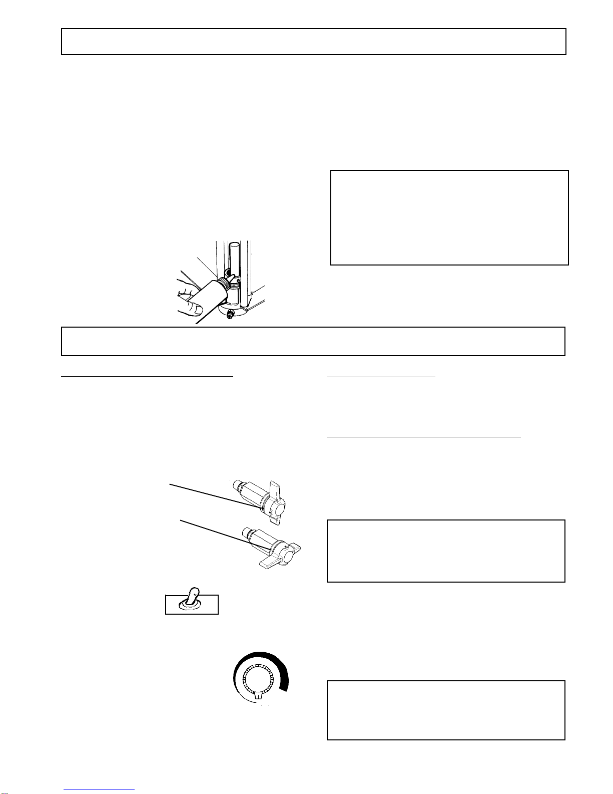
FIGURE 1 FIGURE 2
REMOVE SPRAY TIP.
ENGAGE GUN SAFETY
LATCH.
HOW TO FLUSH
PRESSURE CONTROL KNOB. (FIG. 2)
is used to adjust pressure. Turn clockwise (CW) to
increase pressure and counterclockwise (CCW) to
decrease pressure.
TOGGLE
SWITCH
ON OFF
FIGURE 3
Prime/Pressure Relief Valve (Prime/PR Valve)
Used to relieve pressure from gun, hose & tip and to
prime the unit when in OPEN position.
(It is in open position
when there is a wider gap
between valve handle and
cam body)
When in CLOSED position,
there is only a very slight gap
between handle & body.
When closed the system is
pressurized.
Handle as a loaded firearm!
3
1. Connect the hose and gun.
a. Remove the plastic cap plug from the outlet tee
and screw a conductive or grounded 3000 psi
airless spray hose onto fluid outlet.
b. Connect an airless spray gun to the other end of
the hose.
c. Do not use steel braided airless hose. Use nylon
braided airless hose only.
NOTE: Do not use thread sealer on swivel unions as
they are made to self-seal. Use thread seal on
tapered male threads only.
3. Check the Electrical Service.
Be sure the electrical service is 120 VAC, 15 amp
minimum, and that the outlet you use is properly
grounded.
4. Grounding
2. Fill the Packing Nut/Wet Cup 1/3 full with Throat
Seal Oil (TSO) supplied.
(Fig 6)
5. Flush the sprayer as per "Flushing - New Sprayer"
on page 1 and "How to Flush on page 2.
STARTING UP
WARNING - To reduce the risk of static
sparking, fire or explosion which can
result in serious bodily injury and property
damage, always ground the sprayer and
system components and the object being
sprayed as instructed on Page 6.
1. Learn the fuctions of the controls. 2. Prepare the Material
a. Prepare the material according to the material
manufacturer's recommendations.
b. Place the suction tube into the material container.
3. Starting the Sprayer (See Fig. 7 , 8 & 9)
a. Prime/PR Valve must be "OPEN" in the priming
position.
b. When you have ensured that gun safety latch is
engaged, attach tip and Safety Guard.
c. Turn the ON-OFF Toggle Switch to the
"ON" position.
d. Turn Pressure Control Knob CW to prime pump.
e. After the pump is primed, turn Prime/PR Valve to
the "Closed" position.
f. Turn Pressure Control Knob to the desired spray
pressure. LCD displays pressure.
g. Disengage the gun safety latch and you are ready
to spray.
WARNING - If you spray into the paint bucket,
always use the lowest spray pressure and main-
tain firm metal to metal contact between gun
and container. See Page 2 Fig. 5 .
WARNING - To stop the unit in an emergency,
turn motor off. Then relieve the fluid pressure
in the pump and hose as instructed in the
Pressure Relief Procedure on Page 6.
FIGURE 6
FIGURE 7
SETTING UP
FIGURE 9
PRESSURE CONTROL KNOB
is used to adjust pressure. Turn clockwise (CW) to
increase pressure and counterclockwise (CCW) to
decrease pressure.
FIGURE 8
TOGGLE
SWITCH
ON OFF
PRIME/PRESSURE (PR) RELIEF VALVE is used to
prime pump and to relieve pressure from gun, hose
and tip.
Prime/Pressure Relief Valve (Prime/PR Valve)
Used to relieve pressure from gun, hose & tip and to prime
the unit when in OPEN position. (It is in open position
when there is a wider gap
between valve handle and
cam body)
When in CLOSED position,
there is only a very slight gap
between handle & body.
When closed the system is
pressurized. Handle as a loaded firearm!
4
4. Adjusting the Pressure
a. Turn the Pressure Control Knob CW to increase
pressure and CCW to decrease pressure.
b. Always use the lowest pressure necessary to
completely atomize the material.
CAUTION - Operating the sprayer at higher pres-
sure than needed, wastes material, causes early
tip wear and shortens sprayer life.
c. If more coverage is needed use a larger tip rather
than increasing the pressure.
d. Check the spray pattern. The tip size and angle
determines the pattern width and flow rate.
5. Cleaning a Clogged Tip.
WARNING - Follow the "Pressure Relief
Procedure" on page 6 .
To reduce the risk of injection, never hold your
hand, body, fingers or hand in a rag in front of
the spray tip when cleaning or checking for a
cleared tip. Always point the gun toward the
ground or into a waste container when checking
to see if the tip is cleared or when using a self-
cleaning tip.
There is an easy way to keep the outside of the tip
clean from material build up:
Every time you stop spraying, for even a minute,
lock the gun and submerge it into a small bucket
of thinner suitable for the material sprayed.
Thinner will dissolve the buildup of paint on the
outside of tip, tip guard and gun much more
effectively if the paint doesn't have time to dry
out completely.
WARNING - Clogged standard (flat) tip - clean
only after the tip is removed from the gun.
FOLLOW THE PRESSURE RELIEF
PROCEDURE WARNING ON PAGE 6.
6. When Shutting off the Sprayer
a. Whenever you stop spraying, even for a short
break, follow the "Pressure Relief Procedure Warning"
on page 6.
b. Clean the tip & gun as recommended in gun
instruction manual.
c. Flush the sprayer at the end of each work day, if
the material you are spraying is water-based, or if it
could harden in the sprayer overnight. See "Flushing"
pages 1 and 2. Use a compatible solvent to flush,
then fill the pump and hoses with an oil based solvent
such as mineral spirits.
d. For long term shutdown or storage, refer to page 1.
WARNING - Be sure to relieve pressure in
the pump after filling with mineral spirits.
STARTING UP continued
WARNINGS
Note: United States Government safety stan-
dards have been adopted under the Occupational
Safety & Health Act. These standards, particularly
the General Standards, Part 1910 & Construction
Standards, Part 1926 should be consulted.
WARNINGS CONTINUED ON NEXT PAGE.......
DO NOT USE halogenated solvents in this sytem. The
prime valve, and most airless guns have aluminum
parts and may explode. Cleaning agents, coatings,
paints or adhesives may contain halogenated
hydrocarbon solvents. DON'T TAKE CHANCES!
Consult your material suppliers to be sure. Some of
the most common of these solvents are:
Carbontetrachloride, Chlorobenzene, Dichloroethane,
Dichloroethyl Ether, Ethylbromide, Ethylchloride,
Tethrachloethane. Alternate valves and guns are
available if you need to use these solvents.

5
WARNINGS continued
Hazardous fluid or toxic fumes can cause serious in-
jury or death if splashed in eyes or on skin, inhaled or
swallowed. Know the hazards of the fluid you are us-
ing. Store & dispose of hazardous fluids according
to manufacturer, local, state & national guidelines.
ALWAYS wear protective eyewear, gloves, clothing
and respirator as recommended by fluid manufacturer.
TOXIC FLUID HAZARD
HIGH PRESSURE SPRAY CAN CAUSE EXTREMELY SERIOUS INJURY. Handle as you would a
loaded firearm. Follow PRESSURE RELIEF PROCEDURE on page 6. Observe all warnings.
MEDICAL ALERT -Airless Spray Wounds
If any fluid appears to penetrate your skin, get
EMERGENCY MEDICAL CARE AT ONCE.
DO NOT TREAT AS A SIMPLE CUT.
Tell the doctor exactly what fluid was injected.
NOTE TO PHYSICIAN: Injection in the skin is a trau-
matic injury. It is important to treat the injury surgi-
cally as soon as possible. DO NOT DELAY treat-
menttoresearchtoxicity.Toxicity is a concern with some
exotic coatings injected directly into the blood stream. Con-
sultation with a plastic surgeon or reconstructive hand sur-
geon may be advisable.
GENERAL PRECAUTIONS
NEVER alter equipment in any manner.
NEVER smoke while in spraying area.
NEVER spray highly flammable materials.
NEVER use around children.
NEVER allow another person to use sprayer unless
he is thoroughly instructed on its' safe use and given
this operators manual to read.
ALWAYS wear a spray mask, gloves and protective
eye wear while spraying.
ALWAYS ensure fire extinquishing equipment is
readily available and properly maintained.
NEVER LEAVE SPRAYER UNATTENDED WITH PRES-
SURE IN THE SYSTEM. FOLLOW PRESSURE RELIEF
PROCEDURES ON PAGE 6.
Fluids under high pressure from spray or leaks can
penetrate the skin and cause extremely serious
injury, including the need for amputation.
NEVER
point the spray gun at anyone or any part of
the body.
NEVER
put hand or fingers over the spray tip. Do not
use rag or other materials over your fingers. Paint will
penetrate through these materials and into the hand.
NEVER
try to stop or deflect leaks with your hand or
body.
ALWAYS
have gun tip guard in place when spraying.
ALWAYS lock gun trigger when you stop spraying.
ALWAYS remove tip from the gun to clean it.
NEVER try to "blow back" paint, this is not an air spray
sprayer.
ALWAYS follow the PRESSURE RELIEF PROCE-
DURE, as shown on page 6, before cleaning or remov-
ing the spray tip or servicing any system equipment.
Be sure equipment safety devices are operating prop-
erly before each use.
Tighten all fluid connections before each use.
MEDICAL TREATMENT
If any fluid appears to penetrate your skin, get EMER-
GENCY CARE AT ONCE. DO NOT TREAT AS A
SIMPLE CUT.
* Go to an emergency room immediately.
* Tell the doctor you suspect an injection injury.
* Tell him what kind of material you were spraying with
and have him read NOTE TO PHYSICIAN above.
INJECTION HAZARD ALWAYS INSPECT SPRAYING AREA
Keep spraying area free from obstructions.
Make sure area has good ventilation to safely remove
vapors and mists.
NEVER keep flammable material in spraying area.
NEVER spray in vicinity of open flame or other
sources of ignition.
Spraying area must be at least 20 ft. away from spray
unit.
SPRAY GUN SAFETY
ALWAYS set safety lock on the gun in "LOCKED" posi-
tion when not in use and before servicing or cleaning.
DO NOT remove or modify any part of gun.
ALWAYS REMOVE SPRAY TIP when cleaning. Flush
unit with LOWEST POSSIBLE PRESSURE.
CHECK operation of all gun safety devices before each
use.
Be very careful when removing the spray tip or hose
from gun. A plugged line contains fluid under pressure.
If the tip or line is plugged, follow thePRESSURE RE-
LIEF PROCEDURE as outlined on page 6.
TIP GUARD
ALWAYS have the tip guard in place on the spray gun
while spraying. The tip guard alerts you to the injection
hazard and helps prevent accidentally placing your fin-
gers or any part of your body close to the spray tip.
SPRAY TIP SAFETY
Use extreme caution when cleaning or changing spray
tips. If the spray tip clogs while spraying, engage the
gun safety latch immediately. ALWAYS follow the
PRESSURE RELIEF PROCEDURE and then remove
the spray tip to clean it.
NEVER wipe off build up around the spray tip.
ALWAYS remove tip & tip guard to clean AFTER
pump is turned off and the pressure is relieved by fol-
lowing the PRESSURE RELIEF PROCEDURE.

6
HOSES
Tighten all fluid connections securely before each use.
High pressure fluid can dislodge a loose coupling or
allow high pressure spray to be emitted from the coup-
ling and result in an injection injury or serious bodily
injury.
WARNINGS continued
PRESSURE RELIEF PROCEDURE
To avoid possible serious body injury, always follow this procedure whenever the sprayer is shut off,
when checking it, when installing, changing or cleaning tips and whenever you stop spraying or when you
are instructed to relieve the pressure.
Ground the sprayer & other components in the system
to reduce the risk of static sparking, fire or explosion
which can result in serious bodily injury and property
damage. For detailed instructions on how to ground,
check your local electrical code.
ALWAYS ensure switch is in OFF position before
plugging unit in.
GROUNDING
NEVER use a damaged hose, which can result in
hose failure or rupture and cause an injection injury or
other serious bodily injury or property damage. Before
each use, check entire hose for cuts, leaks, abrasion
or bulging of cover, or damage or movement of coup-
lings. If any of these conditions exist, replace the hose
immediately. Never use tape or any device to try to
mend the hose as it cannot contain the high pressure
fluid. NEVER ATTEMPT TO RECOUPLE THE HOSE.
High pressure hose is not recoupleable.
Use only hose having a spring guard. The spring
guard helps protect the hose from kinks or other
damage which could result in hose rupture and
cause an injection injury.
2. Air Hoses; use only grounded hoses.
3. Fluid hose: use only grounded hoses.
4. Spray gun or dispensing valve; grounding is ob-
tained through connection to a properly grounded fluid
hose and pump.
5. Object being sprayed; according to your local code.
6. All solvent pails used when flushing.
Once each week, check electrical resistance of hose
(when using multiple hose assemblies, check overall
resistance.) Overall (end to end) resistance of
unpressurized hose must not exceed 29 megohms
(max.) for any coupled length or combination of hose
lengths. If hose exceeds these limits, replace it imme-
diately.
Never exceed 500 ft. (150 m) overall combined hose
length to assure electrical continuity.
1. Engage gun safety latch. Refer to separate
instruction manual provided with your gun on its
safety features and how to engage safety latch.
4. Turn Prime/pressure relief valve (PR
Valve) to the open (priming) position to
relieve residual fluid pressure.
There will
be a wider gap between valve handle
and cam body when in open position
.
Note: When in closed position there is only a very
slight gap.
Note: The valve handle can move both
CCW & CW and can face different direc
tions.
2. Turn unit off and unplug from electrical outlet.
3. Disengage gun safety latch and trigger gun to
relieve residual fluid pressure.
Hold metal part of the gun in
contact with grounded metal pail.
USE MINIMUM PRESSURE !
5. Re-engage gun safety latch and
close prime/pressure relief valve.
Always ground all of these components.
1. Sprayer: plug the power supply cord, or extension
cord, each equipped with an undamaged three-prong
plug, into a properly grounded outlet. DO NOT USE AN
ADAPTER.
Use only a 3 wire extension cord that has a 3 blade
grounding plug, and a 3 slot receptacle that will accept
the plug on the product. Make sure your extension cord
is in good condition. When using an extension cord, be
sure to use one heavy enough to carry the current your
product will draw. (Note: The table on the top of the
next page shows the correct size to use depending on
cord length and name plate ampere rating. If in doubt,
use the next heavier gauge. The smaller the gauge num-
ber, the heavier the cord.
If the SPRAY TIP OR HOSE IS CLOGGED, follow Step 1 through 5 above. Expect paint splashing into the
bucket while relieving pressure during Step 4. If you suspect that pressure hasn't been relieved due to
damaged prime/pressure relief valve or other reason, engage gun safety latch and take your unit to
an authorized Airlessco Service Center.

7
WARNINGS continued
KEEP CLEAR OF MOVING PARTS
Always follow recommended pressure and operating
instructions.
ALWAYS use approved high pressure fittings and re-
placement parts.
ALWAYS ensure fire extinquishing equipment is readily
available and properly maintained.
FLUSHING
WHEN SPRAYING & CLEANING WITH FLAMMABLE PAINTS AND THINNERS
1. When spraying with flammable liquids, the unit must be located a minimum of 25 feet away from the spraying
area in a well ventilated area. Ventilation must be sufficient enough to prevent the accumulation of vapors.
2. To eliminate electrostatic discharge, ground the spray unit, paint bucket & spraying object. See GROUNDING
on pg. 6. Use only high pressure airless hoses approved for 3000 psi which is conductive.
3. Remove spray tip before cleaning gun and hose. Make contact of gun with bucket and spray without the tip in
a well ventilated area, into the grounded steel bucket.
4. Never use high pressure in the cleaning process. USE MINIMUM PRESSURE.
5. Do not smoke in spraying/cleaning area.
5 - 6
6 - 8
8 - 10
10 - 12
120
120
120
120
25
18
18
18
16
400
8
6
6
4
300
8
6
6
6
250
10
8
8
6
200
10
10
8
8
150
12
10
10
8
100
12
12
12
10
50
16
16
14
14
500
6
6
4
4
UL RECOMMENDATION FOR MINIMUM GAUGE EXTENSION CORD
Keep clear of moving parts when starting or operating
the sprayer. Do not put your fingers into any openings to
avoid amputation by moving parts or burns on hot parts.
Precaution is the best insurance against an accident.
When starting the motor, maintain a safe distance from
moving parts of the equipment. Before adjusting or ser-
vicing any mechanical part of the sprayer, follow the
PRESSURE RELIEF PROCEDURE on page 6.
AVOID COMPONENT RUPTURE
This sprayer operates at 3000 psi (205 bar). Always
be sure that all components and accessories have a
maximum working pressure of at least 3000 psi to avoid
rupture which can result in serious bodily injury includ-
ing injection and property damage.
NEVER leave a pressurized sprayer unattended to
avoid accidental operation of it, which could result in
serious bodily injury.
ALWAYS follow the PRESSURE RELIEF PROCE-
DURE whenever you stop spraying and before adjust-
ing, removing or repairing any part of the sprayer.
NEVER alter or modify any part of the equipment to
avoid possible component rupture which could result in
serious bodily injury and property damage.
NEVER use weak or damaged or non-conductive paint
hose. Do not allow kinking or crushing of hoses or al-
low it to vibrate against rough or sharp or hot surfaces.
Before each use, check hoses for damage and wear
and ensure all fluid connections are secure.
REPLACE any damaged hose. NEVER use tape or any
device to mend the hose.
NEVER attempt to stop any leakage in the line or fit-
tings with your hand or any part of the body. Turn off
the unit and release pressure by following PRESSURE
RELIEF PROCEDURE.
PREVENT STATIC SPARKING FIRE/EXPLOSIONS
ALWAYS be sure all equipment & objects being sprayed
are properly grounded. Always ground sprayer, paint
bucket and object being sprayed. See grounding on
page 6 for grounding information.
Reduce the risk of injection injury, static sparking or
splashing by following the specific cleaning process.
ALWAYS follow the PRESSURE RELIEF PROCE-
DURE on page 6.
ALWAYS remove the spray tip before flushing. Hold a
metal part of the gun firmly to the side of a metal pail
and use the lowest possible fluid pressure during flush-
ing.
NEVER use cleaning solvents with flash points below
140 degrees F. Some of these are: acetone, benzene,
ether, gasoline, naptha. Consult your supplier to be sure.
NEVER SMOKE in the spraying/cleaning area.
Use only conductive fluid hoses for airless applications.
Be sure gun is grounded through hose connections.
check ground continuity in hose & equipment. Overall
(end to end) resistance of unpressurized hose must not
exceed 29 megohms for any coupled length or combi-
nation of hose length. Use only high pressure airless
hoses with static wire approved for 3000 psi.
Vapors created when spraying can be ignited by sparks.
To reduce the risk of fire, always locate the sprayer at
least 20 feet (6 m.) away from spray area. Do not plug
in or unplug any electrical cords in the spray area, which
can create sparks, when there is any chance of igniting
vapors still in the air. Follow the coating & solvent manu-
facturers safety warnings and precautions.
VOLTAGE LENGTH OF CORD IN FEET
AMPERAGE
RATING
RANGE

8
MAJOR COMPONENTS OF SPRAY GUN
AND REVERSIBLE SPRAY TIP
SPRAY GUN
Attach spray gun to whip hose and tighten fittings
securely. Set the gun safety latch.(Also may be called
gun safety lock) * Refer to Fig. A.
* The gun safety latch should always be set when the
gun is not being triggered.
Read all warnings and safety precautions supplied with
the spray gun and in product manual.
SPRAY TIP ASSEMBLY
FIG. A
RELEASED
GUN SAFETY
LATCH
IN LOCKED
POSITION
AIRLESSCO 007 SPRAY GUN
1. Be sure the pressure relief procedure is followed
before assembling tip and housing to the gun.
2. Insert Rev-Tip cylinder into REV-GUARD (guard
housing assembly).
3. Guide the metal seat into REV-GUARD (guard housing
assembly) through the retaining nut and turn until it seats
against the cylinder.
4. Insert the O ring gasket onto the metal seat so that it
fits into the grooves.
5. Finger tighten the REV-GUARD retaining nut onto the
gun.
6. Turn guard in the desired position.
7. Completely tighten the retaining nut.
REV-TIP
REV
GUARD
O-RING
GASKET
METAL
SEAT
O-Ring Gasket
Metal Seat
Rev-Tip
Cylinder
Retaining Nut
SprayPositionShown
Reverse to
Unplug
REV-GUARD
Guard Housing Assembly
TO REMOVE CLOGS
FROM SPRAY TIP
1. Turn Rev-Tip handle 180
degrees.
2. Disengage gun safety latch
and trigger gun into pail.
3. Engage gun safety latch
and return handle to
spraying position.
Handle
(filter inside)
Reversible
Spray Tip
& Guard Gun Safety
Latch (or Lock)
Trigger
Guard
GUN
SAFETY
LATCH
9
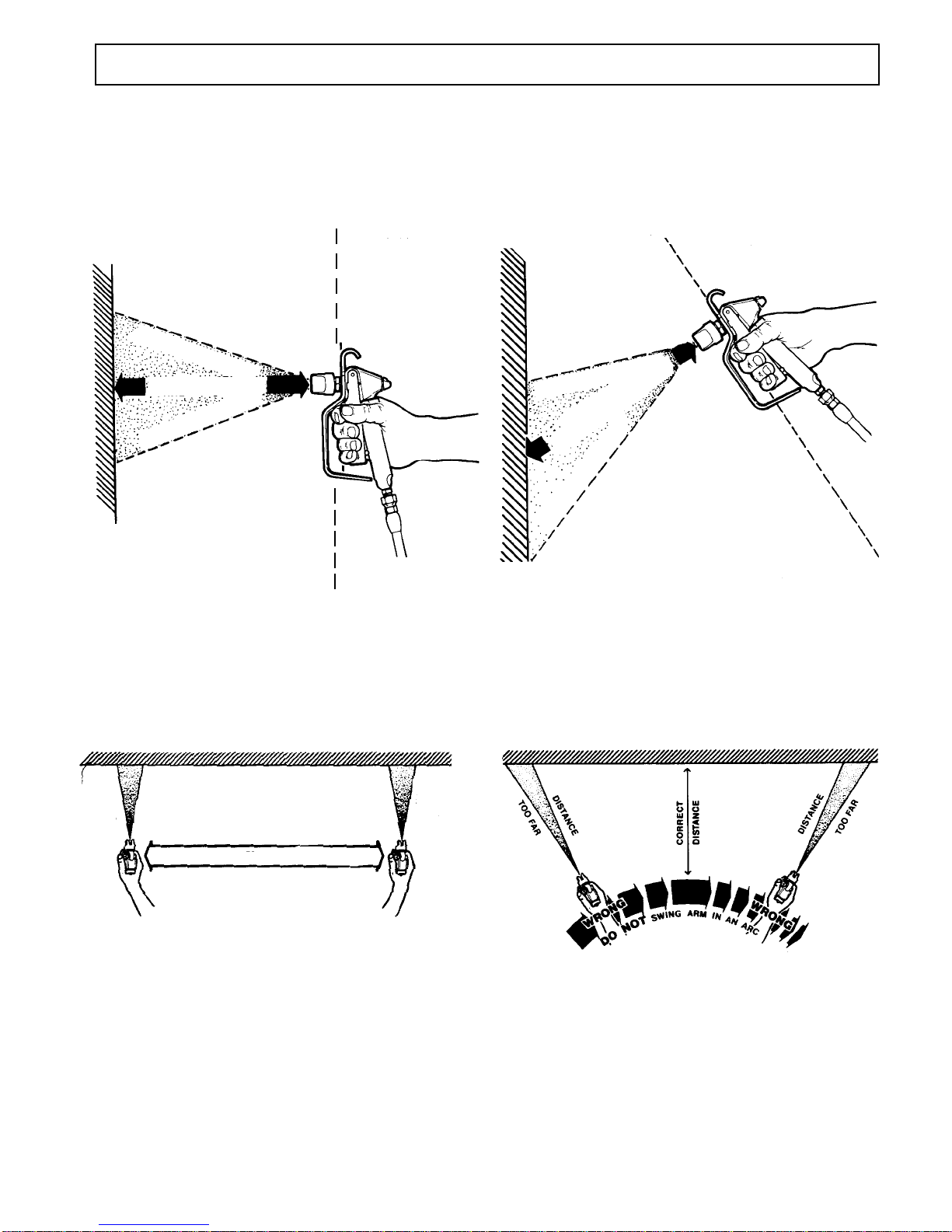
SPRAY TECHNIQUE
Good Spray Gun Technique is at the core of any spray
paint operation. Operator skill and efficiency is as important
as good equipment and good paint. Good spray technique
is a skill that can be quickly learned by following these
simple instructions.
If you are not familiar with spraying techniques, we
recommend that you study this section of your manual
and practice the proper technique on pieces of card-
board or a suitable surface.
RIGHT WRONG
WRONG
Equal spray distance
Equal amount of paint
RIGHT
Equal amount of paint
Equal spray distance
Hold gun straight
up and down
TILTED GUN ANGLE
causes uneven paint coating
Shorter spray distance
Excessive paint spray
Insufficient paint spray
Longer spray distance
TILTED GUN
WRONG
CORRECT DISTANCE
CORRECT GUN ANGLE
Hold the spray gun 12 - 15 inches away from the work surface and keep it perpendicular (straight) to the surface. Move
the spray gun parallel to the work and at a right angle to the surface.
RIGHT
Move the gun at a steady rate in order to apply a good
coverage. The wet coat should be just under the
thickness at which a run or sag will occur. Slow gun
movement or gun held too close will result in an overly
wet or thick wet or thick coat coverage that is likely to
run or sag.
Do not wave the spray gun. This waving is called
arching. Instead, hold the spray gun at a 12 to 15 inch
distance perpendicular from the work.
The closer the spray gun is held to the work, the thicker
the paint is deposited and the faster the gun must be
moved to prevent sags and runs. Holding the gun too
far from the work will cause excessive fog, overspray,
and a thin and grainy coat.
WRONG
Keep parallel to surface.

10
SPRAY TECHNIQUE
TOTAL SPRAYGUN MOVEMENT - arm movement - full sweep
The Actual Paint Stroke
TRIGGER POINT
TRIGGER
POINT
It is important to "trigger" the gun after gun movement
(arm movement) has started and release trigger (shut
gun off) before gun movement ends. Gun movement is
always longer than actual paint (spray) stroke. In that
manner, even blending and uniform paint coat thickness
is achieved over the entire surface. When the gun is in
motion as the trigger is pulled, it deposits an even
amount of paint.
Overlap the previous pass by half the width of the spray
pattern. Aim at the bottom of the previous pass.
Spray with uniform strokes from left to right and from
right to left, holding stroke speed, distance, lapping,
and triggering as uniform as possible.
FOR EVEN PAINT COAT, OVERLAP
HALF THE WIDTH OF EACH PAINT
STROKE.
Adjust pressure control knob so that paint is completely
atomized from the spray gun. Insufficient pressure will
result in "tailing".
Too much pressure will result in excess fog and
overspray, excessive tip wear, and increased sprayer
wear and tear.
TAILING GOOD PATTERN FOG, OVERSPRAY
"Inside" and "outside" corners can be sprayed.
Aim the spray gun toward the center of the corner. The
spray pattern is divided in half, and the edges of the
spray pattern on both walls are the same.
Always use the lowest pressure possible to obtain
desirable results.
Test the spray pattern on a piece of cardboard or other
surface.
POOR PATTERN GOOD PATTERN
INSIDE CORNER OUTSIDE CORNER

11
AIRLESS SPRAY GUN OPERATION
DEFECTS CAUSE CORRECTION
Coarse spray Low pressure Increase the pressure.
Excessive fogging High pressure Reduce the pressure to satisfactory pattern distribution.
(overspray) Material too thin Use less thinner.
Pattern too wide Spray angle too large Use smaller spray angle tip.
Pattern too narrow Spray angle too small Use larger spray angle tip. (If coverage is OK, try tip
in same nozzle group)
Too much material Nozzle too small Use next smaller nozzle.
Material too thin
Pressure too high Reduce pressure.
Too little material Nozzle too small Use next larger nozzle.
Material too thick
Thin distribution in Worn tip Change for new tip.
center of pattern Wrong tip Use nozzle with a narrow spray angle.
"horns".
Thick skin on work Material too viscous Thin cautiously.
Application too heavy Reduce pressure and/or use tip in next larger nozzle
group.
Coating fails to Material too viscous Thin cautiously.
close & smooth over
Spray pattern irreg- Orifice clogged. Clean carefully.
ular, deflected Tip damaged Replace with new tip.
Craters or pock Solvent balance Use 1 to 3% "short" solvents remainder "long" solvents.
marks, bubbles (This is most likely to happen with material of low
on work viscosity, lacquers etc.)
Clogged screens Extraneous material Clean screen
in paint.
Coarse pigments Use coarse screen if orifice size allows.
Poorly milled pigments Use coarser screen, larger orifice tips. Obain ball
(paint pigments glocculate milled paint. If thinner has been added, test to see if a
cover screen. Incompatible drop placed on top of paint mixes or flattens out on the
paint mixture & thinners. on the surface. If not, try different thinner in fresh
batch of paint.
TEST THE PATTERN
Good, full Spotty Pattern
Increase Pressure.

12
SPRAY TIP SELECTION
Spray tip selection is based on paint viscosity, paint
type, and job needs. For light viscosities (thin paints),
use a smaller tip; for heavier viscosities (thicker paints),
use a larger tip size.
PATTERN WIDTH
Thickness of the paint coat per stroke is determined by
spray tip "fan width", rate of the spray gun movement,
and distance to surface.
SPRAY TIP SELECTION
Two tips having the same tip size, but different pattern
widths will deliver the same amount of paint over a
different area (wider or narrower strip).
A spray tip with a narrow pattern width makes it easy to
spray in tight places.
Use only good quality, high pressure tungsten carbide
spray tips.
* Larger Sizes Available
NOTE: For materials requiring larger than a
.021 tip, refer to Manufacturers label specifications.
SPRAY TIP REPLACEMENT
During use, especially with latex paint, high pressure
will cause the orifice to grow larger. This destroys the
pattern.
Replace tips before they become excessively worn.
Worn tips waste paint, cause overspray, make
cutting-in difficult, and decreases sprayer performance.
REGULAR MAINTENANCE
1. Keep the displacement pump packing nut/wet cup 1/3 full of TSO (Throat Seal Oil) at all times. The TSO
helps protect the packings and rod.
2. Inspect the packing nut daily. Your pump has a patented Triple Life Packing System. Packing life will be
extended a minimum of three times if the following "Packing Tightening" procedure is followed:
Inspect the packing nut daily. If seepage of paint into the packing nut and/or movement of
the piston upward is found (while not spraying), the packing nut should be tightened enough
to stop leakage only, but not any tighter. Overtightening will damage the packings and reduce
the packing life.
Spray tip size is based on how many gallons of paint
per minute can be sprayed through the tip. Do not use
a tip larger than the maximum pump flow rate or capac-
ity the sprayer can accommodate. Pump flow rate is
measured in gallons per minute (GPM).

13
ELECTRIC MOTOR MAINTENANCE
1. LUBRICATION - This motor is supplied with prelubricated ball bearings, lubricated for life of bearing.
2. MOTOR BRUSHES need periodic inspection and replacement as wear indicates. Brush wear is greatly influ-
enced by individual application. It is recommended that brush wear be checked at early intervals of operation in
order to determine future required inspections. Standard Leeson brushes for this motor have an initial length of
3/4". When the brushes are worn to a length of 3/8", they should be replaced.
3. TO CHANGE THE BRUSHES, follow the procedures below:
a. Unplug the machine.
b. Open the two covers at the rear of the motor.
c. Loosen the screw holding the brush terminal and remove the brush lead.
d. Push the brush retainer clip in and remove.
e. Remove the worn brushes (one on each side of motor).
f. Install new brushes in reverse order and replace covers.
NOTE: For longer life, new brushes (Part No. 331-131) need to have a run in period. After changing brushes, set
up the machine for spraying. Use a bucket of water and Coro-chek mixture, a 50 foot x 1/4" airless hose, airless
gun with 0.017 tip on unit, turn the Prime/PR Control Valve to the Prime position and turn the unit on. Turn the
Pressure Control Knob to maximum pressure (fully CW position) and let the pump cycle at high speed in the prime
position for 20 minutes. This will allow the brushes to "run in" properly, giving a longer life.
TROUBLESHOOTING
PROBLEM CAUSE SOLUTION
The fluid supply is low or empty.
Air entrapped in the fluid pump or
hose.
The wet cup is loose.
The throat packings are worn or
damaged.
Piston Rod is Worn.
The pressure setting is too low.
The pump is seized by dried paint.
The pressure setting is too low.
The tip or gun filter is clogged.
Tip is worn.
The fluid displacement pump
filter is clogged.
There is a large pressure drop
in the fluid hose.
Refill the supply container.
Check for loose connections on the
siphon assembly, tighten, then reprime
pump.
Tighten just enough to stop leakage.
Replace the packings. See page 21.
Replace Piston Rod.
Increase the pressure.
Service the pump. See pages 20 & 21.
Increase the pressure.
Remove the tip and/or filter and
clean them.
Replace Tip.
Clean the filter.
Use a larger diameter hose.
There is spitting from the gun.
Paint leaks into the wet cup.
The motor operates, but the
paint pump doesn't.
The motor and displacement
pump operates, but paint
pressure is too low or none.

14
TROUBLESHOOTING- Machine does not start.
CAUSE SOLUTION
STEP 1: Ensure that the ON-Off toggle switch is in the "ON" position and that the
Pressure Control Knob is fully CW (maximum pressure). Also check that
the unit is plugged in.
Control Settings
Power Source STEP 3: Use a multimeter to check for 110 volts VAC across the L1 and L2
terminals on the board. If there is no voltage at these leads, there is
no power to the unit. Check power source (outlet, breakers, extension
cord and power cord).
STEP 2: Remove the electrical cover on the bottom of the machine. Check if the
green power light on the board is lit. If the light is "OFF", proceed to
Step 3. If the light is "ON", go to Step 7.
STEP 4: If the machine has power and the green light is "OFF", test the fuse for
continuity or replace with a new fuse.
Fuse
Thermal Overload
Pressure Control Assembly
(Board)
Sensor
Pressure Control
Knob (Potentiometer)
Motor
STEP 5: If the fuse is okay, disconnect the two red motor leads (S1 & S2) and
test for continuity between the two leads. Continuity shows that the
motor's thermal coupler has not tripped. No continuity means that the
thermal coupler has opened due to excessive motor heat. If the motor
is still hot to touch, allow to cool and retest. If the motor is cool and there
is no continuity on the red leads, contact your local Leeson repair facility
to repair/ replace the thermal coupler.
STEP 6: If all checks out fine in Steps 1 through 5 and the green light is still out,
the pressure control assembly is defective and must be replaced.
STEP 7: If the green light is "ON", the power source, fuse and thermal coupler are
okay. Plug another sensor into the board. If the unit starts, the sensor was
faulty and must be replaced. When a replacement sensor is not available,
use a multimeter to test the resistance between the BLACK and RED wires
on the sensor lead. The resistance should be approximately 1.5-3.5 kohms.
A faulty sensor usually reads zero resistance (open).
STEP 8: With the machine still "OFF", remove the potentiometer lead from the
board and read the resistance between the red and black wires. This
must be 8 - 12 kohms. If outside this range, replace the potentiometer.
NOTE: A bad POT will usually show no resistance (open).
STEP 10: Remove the two black motor leads (A1 & A2) and test for continuity
between them. Continuity is an indication that the motor is sound. The
lack of continuity, points to a problem in the motor. If there is no
continuity on these two leads, check the motor brushes. Ensure that
the brushes are evenly worn and make solid contact with motor
commutator. Replace the brushes if they are less than 3/8" long. If the
brushes are okay, replace the motor.
STEP 11: Calibrate the pressure control assembly in accordance with the
instructions on page 15.
STEP 12: If the unit fails to calibrate and all components in Steps 1-10 test okay,
the pressure control assembly needs to be replaced.
Pressure
Calibration
Pressure Control Assembly
(Board)

15
ELECTRICAL BOARD CALIBRATION
Note: Anytime a sensor, pressure control assembly (board) or both are replaced,
the following three calibrations must be performed.
1. ZERO CALIBRATION
1. Place prime/pressure relief valve in the prime (open) position.
2. Set the presssure control knob to the minimum setting (CCW).
3. Remove the screws (Fig. 17, Item 20) and lower the pressure control assembly.
4. Ensure the jumper is on the "P-ZR" terminal. Note: This jumper comes with a new pressure control assem-
bly (board) and is installed on the "P-ZR" terminals. If you are "Zero Calibrating" a pressure control assem-
bly presently in the unit, remove Jumper from Single Terminal P-ZR and place on both terminals P-ZR.
When Zero Calibration is complete replace jumper on a single terminal of P-ZR.
5. Turn machine "ON" and ensure it is not cycling.
6. If the yellow light on the electrical board is ON, use an insulated screwdriver to turn the "ZERO" trimpot
counter-clockwise until the light goes out. Then turn it clockwise until the light just comes back on. Look at
the LCD Display and if "0000" is showing the Zero Calibration is complete. If the display shows more than
"0000", turn the Zero Trimpot CCW until "0000" is showing. If "-- -- --" is showing, turn the zero trimpot CW
until "0000" is displayed.
7. If the yellow light is OFF, turn the "Zero" trimpot clockwise, just until the light comes on and stop. Confirm
"0000" is displayed.
NOTE: If the yellow light remains constantly "ON", or "OFF" during this calibration, the sensor is defective
and should be replaced.
8. When calibration is complete, move jumper from both "PZ-R" terminals to single terminal on P-ZR.
2. PRESSURE CALIBRATION
1. Attach a 50', 1/4" airless hose, airless gun with 0.017 tip and a 5000 psi glycerine filled pressure gauge to
the pump.
2. Place the suction tube into a bucket of Coro-chek and water.
3. Turn Prime/pressure relief valve to the prime (open) position.
4. Complete the ZERO calibration, as per "ZERO CALIBRATION".
5. Turn pressure control knob clockwise until machine starts to prime.
6. Place the prime/pressure relief valve in the pressure (closed) position.
7. While watching pressure gauge, slowly adjust the Pressure Trimpot (clockwise to increase and counter
clockwise to decrease) until the maximum static pressure is 3000 psi, with the pressure control knob fully
clockwise. Trigger the gun several times to ensure pressure returns to 3000 psi .
1. Attach a 50', 1/4" airless hose, airless gun with .017 tip and a 5000 psi glycerine filled pressure gauge to the
pump.
2. Place the suction tube into a bucket of antifreeze (or Coro-chek) and water.
3. Turn pump ON and turn up pressure control until the machine starts to prime.
4. Place the prime/pressure relief valve in the pressure (closed) position.
5. Pressurize pump to 600 psi.
6. Trigger the gun several times noting the deadband (the amount of pressure drop before the pump rebuilds to
set pressure).
7. If deadband is greater than 100 psi, adjust the low pressure voltage trimpot so that the deadband is less than
100 psi and the pressure increase after the gun trigger is released is less than 200 psi. These pressures are
guidelines and may vary slightly from pump to pump.
3. LOW PRESSURE VOLTAGE TRIMPOT CALIBRATION

16
ELECTRICAL SYSTEM
FIGURE 10
BLK
GREEN
2
1
3
4567
10
11
12
13
SENSOR
P-ZR
ZERO
LIGHT
8
L1
S1 S2
L2
A1
A2
PRESSURE
ZERO
RED
BLK
WHITE BLK/WHITE
POWER
LIGHT
BLK
LOW PRESSURE
VOLTAGE
TRIMPOT
POT
9
RED
BLK
NOT USED
EMPTY
Electrical Power Cord
Strain Relief
Screw
Toggle Switch
Fuse 12A Slow Blow ( 400E )
Fuse 20A Slow Blow ( 500E,600E)
Fuse Holder
1/2 HP DC Motor (400E)
3/4 HP DC Motor (500E, 600E)
Pressure Control Ass'y
Jumper
Sensor
Potentiometer
Spacer
Knob
331-168C
331-185
331-138
331-311
331-165
331-328
331-312
331-070
331-068
331-315
117-207
331-294
331-297
331-184
117-044
1
2
3
4
5
6
7
8
9
10
11
12
13
FIGURE 10 PARTS LIST
ITEM NO. PART NO. DESCRIPTION

17
REPLACEMENT OF ELECTRICAL COMPONENTS
NOTE: Anytime the pressure control assembly, sensor or both are replaced, perform the three calibrations on page 14.
WARNING: Always unplug the electrical cord before servicing machine.
PRESSURE CONTROL ASSEMBLY (Electrical Control Board)
1. Unplug machine's power cord.
2. Remove four screws (Item 20, Fig. 17) from pressure control assembly.
3. Disconnect all leads from pressure control assembly. (Fig. 10).
4. Reassemble in reverse order.
SENSOR
1. Remove the screws (Item 20, Fig. 17) and lower the pressure control assembly.
2. Disconnect swivel (Item 13, Fig. 17) from sensor (Item 14, Fig. 17) by holding sensor with 7/8" wrench and
loosening swivel with 11/16" wrench.
3. Disconnect sensor lead from the board. Carefully pull sensor lead out of the terminal box and remove sensor.
4. Reassemble in reverse order.
POTENTIOMETER (Pressure Control Assembly)
1. Lower pressure control assembly as described above.
2. Disconnect potentiometer lead from pressure control assembly.
3. Use a 1/16" allen wrench, loosen set screw in the potentiometer knob (Item 11, Fig. 10) and remove knob and
spacer. (Item 13, Fig. 10).
4. Using a 1/2" wrench or deep socket, remove the nut from the potentiometer shaft assembly.
5. Pull entire potentiometer assembly out of terminal box.
6. Replace in reverse order.
ON-OFF TOGGLE SWITCH
1. Lower the pressure control assembly as described above.
2. Disconnect the two wires on the switch.
3. Use a 9/16" wrench to loosen the nut on the toggle switch shaft.
4. Reassemble in reverse order.
FUSE HOLDER
1. Lower pressure control assembly as described above.
2. Disconnect the two wires on the holder.
3. Remove holder cover and fuse.
4. Use 11/16" wrench to remove the nut from the holder shaft.

18
NOTE: Check everything in the Troubleshooting
Chart before disassembling the Fluid Pump.
SEE FIG 12, Page 19.
FLUID PUMP DISCONNECT
a. Flush out the material you are spraying, if
possible.
b. Follow the "Pressure Relief Procedure" on
page 6.
c. Remove the suction tube assembly from the
paint pump by unscrewing the suction nut.
Disconnect sensor assembly by holding sensor
with 7/8" wrench and unscrewing swivel connec-
tor with an 11/16" wrench.
d. Move the piston rod to its lowest stroke
position by rotating the motor fan or by cycling
rod to lowest position.
e. Unscrew the two screws (14) from cover
assembly.
f. Slide retaining ring (12) down off crosshead
assembly (3). Push Pin (10) out of crosshead
allowing removal of fluid pump from unit.
FLUID PUMP REINSTALL:
a. Loosen packing nut and extend piston rod to
its upper position in paint pump. Slip sleeve and
retaining ring over piston rod.
b. Push piston rod up into crosshead assembly
and align holes. Insert pin through crosshead
assembly and piston. Insert retaining spring into
groove on crosshead assembly.
c. Secure paint pump to cover assembly by two
screws, up through tube spacers and screw into
cover assembly.
d. Tighten screws evenly and alternating to 20 ft.
lbs.
GEARBOX SLEEVE
BEARING REPLACEMENT
FIGURE 11
FIGURE 11 PARTS LIST
ITEM NO. PART NO. DESCRIPTION
1 331-061 Sleeve Bearing
2 331-103 Washers (2)
3 331-197 Screws (2)
Note: When replacing item (1),
cover the outside of sleeve with clear sili-
cone prior to inserting into cover assembly.
3
1
2
e. Reassemble the Lower Check Valve assem-
bly by placing the Suction Seat Assembly, 0-ring,
ball and retainer in the suction nut and screw nut
onto pump body.
f. Reconnect sensor assembly to fluid pump.
Hold sensor with 7/8" wrench while tightening
swivel connector.
g. Start the pump and operate slowly to check
the Piston Rod for binding. Adjust screws hold-
ing pump assembly to cover assembly if neces-
sary to eliminate binding.
h. Tighten the packing nut until resistance is felt
against the belleville springs, then 1/2 turn more
CW (approximately three threads showing). Fill
the wet cup of Packing Nut 1/3 full of Throat
Seal Oil (TSO).
i. Run unit at full pressure, release pressure &
repeat step h.
SERVICING THE FLUID PUMP
This manual suits for next models
2
Table of contents
Other Allpro Paint Sprayer manuals


