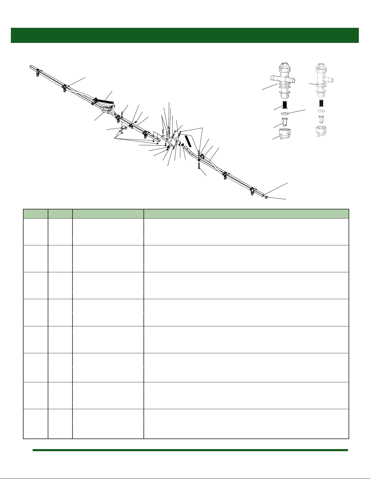
PBZ CropCare ATV-MX160 User manual

13’ Manual Fold Boom
Model ATV-MX160
Form: ATV-MX160OM
Revision A Rev. Date 01/17
Manufactured PBZ LLC
A Paul B Zimmerman Inc. Company
www.CropCareEquipment.com
Owner's Manual

2
Notes

3
Table Of Contents
• Be aware of all safety guidelines, warnings, and cautions including those of the tractor manufacturer.
• Read and understand the chemical manufacturer’s labels, warnings, and instructions.
• Know and fulll all state pesticide applicator license requirements.
• Familiarize yourself and other operators with the sprayer’s components and how all parts are operated.
Before You Begin
Please read and understand this manual and its instructions and warnings completely before operating.
Before You Begin....................................................................................3
Safety Precautions.................................................................................4
Before Operation ........................................................................4
During Operation .......................................................................4
Following Operation .................................................................4
Towing the Sprayer....................................................................4
Assembly Instructions .........................................................................5
Operating Instructions ........................................................................7
Operation ......................................................................................7
Calibrating the Sprayer........................................................................7
Calculating the Speed...............................................................7
Determining Nozzle Size/Using Calibration Chart .........8
Maintenance Instructions ..................................................................8
Winterizing Your Sprayer .........................................................8
Routine Maintenance................................................................9
Breakdowns & Parts Lists ....................................................................9
TeeJet®Nozzle Body Breakdown & Parts List ....................9
ATV-MX160Breakdown.......................................................... 10
ATV-MX160 Parts List ............................................................. 10
CropCare® Limited Warranty........................................................... 11
Odering Parts....................................................................................... 11

4
During Operation
• To avoid injury from chemical hazards, wear the proper
protective clothing. Each chemical manufacturer’s
clothing requirements are listed under the “Personal
Protective Equipment (PPE) section in the chemical’s
instructions
• Always be aware of bystanders, particularly children!
Always look before moving the sprayer or engaging the
pump. Bystanders should never be allowed near the
sprayer during operation.
Towing the Sprayer
• When transporting the sprayer, the sprayer’s boom
must be in the fully folded position.
Safety Precautions
• Completely rinse the entire boom and all of its
components of all chemical residue after every use.
Following Operation
• Dispose of rinsate in accordance with chemical
application guidelines.
• Be aware of dangerous terrain such as holes, slopes,
drop-os, banks, rocks, and hidden hazards. Operate
the tractor and sprayer up and down slopes, not across.
• Allow for sprayer boom length when making turns.
• Rememberthataccidentscanevenhappentoseasoned
operators. Always take your time and follow all safety
instructions.
Before Operation
• Be aware of the location of all the safety and warning
decals. Always replace any decals that are illegible or are
missing.
• Carefully study and understand this owner’s manual.
• Give the boom a visual inspection for any worn parts,
loose bolts, or other visible problems, and make any
necessary repairs. See the maintenance section (page 9).
• All maintenance should be performed with the sprayer
unhooked from the tractor and clean of any harmful
chemicals.
• Make sure the area is clear of any people or obstructions
before using the sprayer.

5
Assembly Instructions
The model ATV-MX160 boom requires some assembly. Follow the step-by-step instructions to ensure proper assembly. Before
assembling, ensure that you have all of the necessary components and parts.
160” Boom Kit Box
Ref. Qty. Description
1 Center boom section
1 Right boom wing section
1 Left boom wing section
1 Boom hardware kit (Figure 1)
a 2 Boom mounting clip
b 2 1” x 8” extension spring
c3 Stainless steel hose clamp
d8 3/8” ange nut
e 4 3/8” at washer
f 4 3/8” acorn nut
g2 3/8” x 1” carriage bolt
h6 3/8” x 2” carriage bolt
1 Nozzle kit (Figure 2)
a 8 Purple polymer spray tip
b 8 Red mesh tip strainer
c 8 Rubber Washer
d 8 Black nozzle cap
d
Figure 1: Boom hardware kit
a
c
b
Figure 2: Nozzle kit
Figure 4: Boom wing mounting
Figure 3: Center frame mounting
a
b
Assembly Instructions
1. Bolt the boom mounting clips (c) to the center section
(a), using 3/8” x 2”bolts (d) and 3/8”ange nuts (e). Bolt
the boom mounting clips to the sprayer frame using 3/8”
x 1” bolts (b) and 3/8” ange nuts (e) (Figure 3).
2. Position the right boom wing (a) as shown and insert the
3/8” x 2” bolts (b) through the holes in the boom wing
hinge and the center frame. Fasten the bolts with 3/8”
ange nuts (c) (Figure 4).
3. Rotate the boom wing towards the center frame to the
closed position.
c
d
e
a
c
b
e
d
f
g
h
a
c
b

6
4. Attach the extension spring (a) to the brace on the center boom section and to the bolt on the boom wing using 3/8” at
washers (c) and 3/8” acorn nuts (b) (Figure 5).
5. Install the left boom wing using the same procedure.
6. Insert the spray tip (a) into nozzle cap (b), then push the rubber washer into the nozzle cap. Insert the tip strainer into the nozzle
body with the mesh facing upward as shown and turn the spray cap onto the nozzle body (Figure 6).
7. Connect the boom supply hose (a) coming from the sprayer tank to the white barbed tee on the center boom section. Insert
the 1/2” barbed tee (b) into the boom supply line and tighten with a hose clamp (c) (Figure 7).
8. Slide hose clamps (b) over the hoses on the boom wings . Connect the boom wing hoses (a) to the black nozzle body hose
barbs (c) on the center boom section. Be sure that the boom wing can open and close with no pinching or stretching of the
hose. Then position the hose clamp (b) directly over the barb and tighten (Figure 8).
Assembly Instructions
Figure 6: Nozzle assembly
Figure 7: Tee/Supply hose
Figure 5: Extension spring mounting
Figure 8: Spray hose installation
a
c
b
a
c
b
a
c
b
d
a
b
c

7
Operating Instructions
1. Unfold the boom by pulling the boom wings toward the
rear of the sprayer as shown (Figure 1).
2. Note: Do not pull on the boom hoses or nozzle bodies,
as this could cause damage to the components.
3. Engage the boom by operating the sprayer’s control
valve(s).
4. When folding the boom, fold the right side boom wing
rst, folding the wing until it rests against the stop on the
hinge. Then fold the left side boom wing to complete
the folding process.
Operation
Figure 1: Unfolding the boom
Note: All calibration needs to be done with water only!
When spraying with the boom, the sprayer must be calibrated to ensure proper spray coverage. Before calibrating the sprayer, it is
important to familiarize yourself with the operating instructions. The calibration process is simplied when broken down into the
following steps:
1. Calculate the speed of the sprayer or equipment.
2. Determine the nozzle size and consult the calibration chart for the desired or instructed Gallons per Acre (GPA).
Calibrating the Sprayer
1. Calculating the Speed
It is important to determine what speed you will be traveling while spraying. Although some tractors may have speedometers,
calculating speed is still recommended for accuracy purposes. To determine the speed follow these four steps:
Note: It is helpful for future references to record the exact RPM and gear used to nd your speed.
1. Measure a 200 foot or 300 foot distance on a eld or a surface similar to where you will be spraying.
2. Drive the equipment and sprayer (half-full is optimal) across the measured distance at a constant rate of speed. There should be
no changes in speed while you are measuring the time. This should be a comfortable speed for spraying.
3. Have someone measure the amount of time (in seconds) it takes to travel the measured distance.
4. Your speed can be calculated by entering your data into the equation Speed (mph) = (Distance (ft) x 60) ÷ (Time (seconds) x 88).

8
2. Determining Nozzle Size/Using Calibration Chart
The spray nozzles on your sprayer are color-coded to match up with the calibration chart. After you have determined your nozzle
size, you need to look at the calibration chart. Using your calculated speed, nozzle size, and desired gallons per acre (GPA), nd the
pressure (psi) necessary to achieve your GPA. It is important to note that lower pressure settings will result in less spray drift.
Example: Assume you have found your calculated speed to be 5 MPH, your nozzles are lavender (110025), and you want to spray
13 GPA. Upon looking at the chart, you nd that you should set the sprayer's pressure at about 29 psi in order to apply 13 GPA.
Tip Size PSI GPM of one
nozzle
Gallons Per Acre (GPA)
3 MPH 4 MPH 5 MPH 6 MPH
AIXR
(Lavender)
110025
15 0.15 14.8 11.1 8.9 7.4
20 0.18 17.8 13.4 10.7 8.9
30 0.22 21.8 16.3 13.1 10.9
40 0.25 24.8 18.6 14.9 12.4
Please note: Flow rates are calculated using water.
Winterizing your Sprayer
It is essential that you winterize your sprayer to avoid damage and to allow for optimal performance. The winterization process
should be undertaken before freezing conditions and/or after each season of use. Failure to winterize your sprayer will void the
manufacturer’s warranty.
Note: Please reference your sprayer owners manual for proper winterizing.
Calibrating the Sprayer
Maintenance Instructions

9
Maintenance Instructions
Routine Maintenance
1. It is recommended to perform a visual and physical inspection for worn parts, loose bolts, damaged hoses, or other visible
problems. Make all necessary repairs before spraying. To order parts or receive technical help, please contact the original
retailer
2. After each use it is important to rinse the boom and all components by running water through the entire system.
3. Tip strainers should be taken out and rinsed on a regular basis. Tip strainers are the small screens located behind each spray
nozzle on the boom (Figure 6, page 6).
4. Check the amount of grease between the hinge plate and the boom wing. Add grease as needed to keep the wing folding
smoothly and quietly.
It is very important to perform routine maintenance on your sprayer boom before and after each use. Good maintenance practices
will help to guard against any breakdowns or accidents.
Note: Always wear the proper Personal Protective Equipment (PPE) when performing maintenance on your sprayer.
TeeJet®Nozzle Body Breakdown & Parts List
Breakdowns & Parts Lists
Ref # Qty. Part Number Description
1 1 22251311500NYB Elbow body, 1/2” (shown)
- 1 22252312500NYB Tee body, 1/2”
21CP21953EPR* Rubber diaphragm
312195010NYB* Diaphragm cap, 10 psi
3
1
2
Note: Items 2 & 3 are included with Item 1

10
ATV-MX160 Breakdown
Ref # Qty. Part Number Description
1 12’ 1208 Hose, EPDM Rubber 1/2”200 PSI
2 17 6806052 Hose Clamp, 1/2”- 19/32” SS
3 2 22251311500NYB * Body, Nozzle Elbow 1/2”QJ300
4 6 22252312500NYB * Body, Nozzle Tee 1/2” QJ300
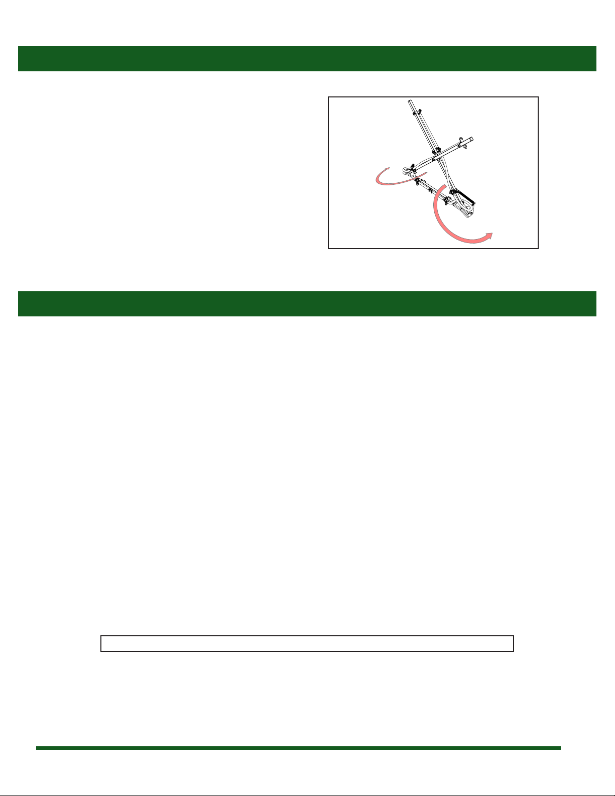
5 8 256121NYR Cap & Gasket, Quick TeeJet Black
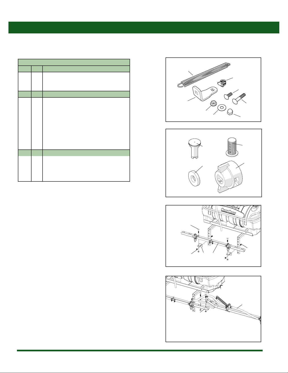
6 2 33*TS Spring, Extension 1” x 8” (8.5” OAL)
7 8 8079PP50 Strainer, Tip 50 Mesh Red Poly Body SS Screen
8 8 AIXR110025VP Tip, AIXR TeeJet Polymer Purple
9 4 AN38 Nut, Acorn 3/8-16
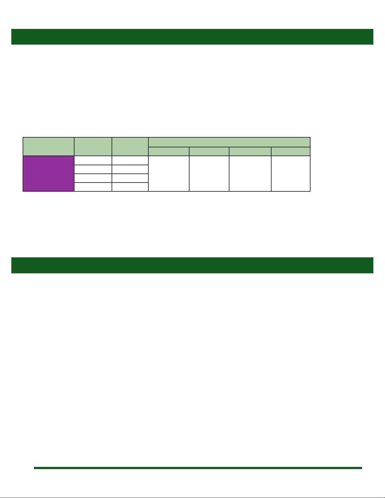
10 1 BF1220 13’ Manual Fold Boom, center tube
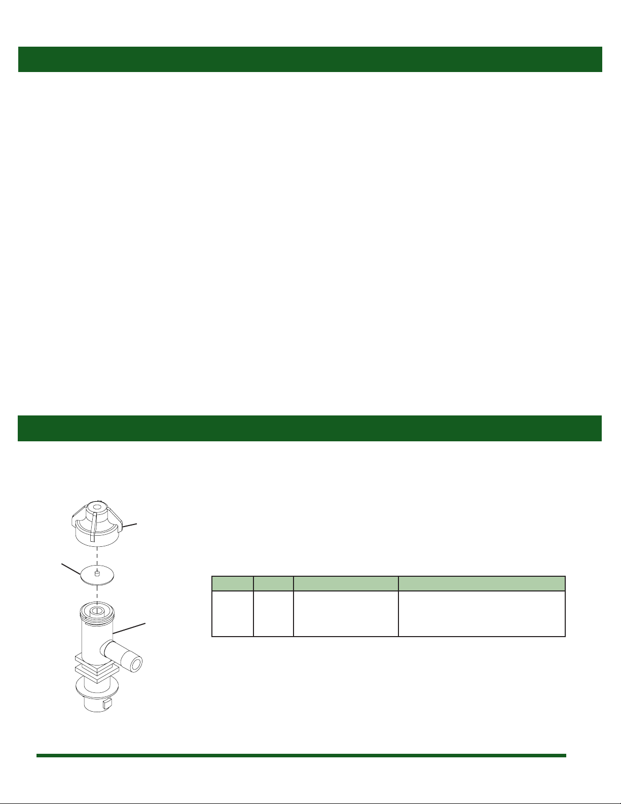
11 1 BF1221 13’ Manual Fold Boom, inner hinge, left
12 1 BF1222 13’ Manual Fold Boom, inner hinge, right
13 2 BF1223 13’ Manual Fold Boom, outer wing
14 2 BF1224 13’ Manual Fold Boom, mounting brackets
15 2 CB38*1G5 Bolt, Carriage 3/8-16 x 1” Gr 5
16 2 CB38*212G5 Bolt, Carriage 3/8-16 x 2-1/2” Gr 5
17 6 CB38*2G5 Bolt, Carriage 3/8-16 x 2” Gr 5
18 2 CB38*312G5 Bolt, Carriage 3/8-16 x 3-1/2” Gr 5
19 4 CC5520 Cap, Poly Square 1-1/4”x 14-20 Ga Blk
20 2 CN38*118 Nut, Coupling 3/8-16 x 1 1/8”
21 2 D-1335 Spring, Die 1/2”Rod ID x 2” x .225x.158 Wire 840lbs/in
22 4 FB38*112G5 Bolt, Flange 3/8-16 x 1 1/2”Gr 5
23 12 FN38 Nut, Flange 3/8-16
24 2 FW12 Washer, Flat 1/2” USS
25 4 FW38 Washer, Flat 3/8”
26 2H5C12*4 Bolt, Hex 1/2-13 x 4” Gr 5
27 2NNC12 Nut, Lock Nylon 1/2-13
28 8QJ111SQ114 Clamp, Nozzle Body 1-1/4”Sq Tube Steel
29 1 T12 Tee, 1/2” Hose Barbs Nylon
30 2 CN38 Nut, Coupling 3/8-16 x 1-3/4”
31 2 H5C38*34 Bolt, Hex 3/8-16 x 3/4” Gr 5
32 2 618UV Cable Tie, 6” 18 Lb black
Breakdowns & Parts Lists
ATV-MX160 Parts List
* Nozzle body breakdown is listed on page 9
Contact the original retailer for ordering information
4
5
7
8
3
5
1
2
6
9
10
11
12
13
14
15
16
17
17
18
19
19
20
21
22
23 23
23
24
25
26
27
28
29
22
30
31
32

11
CropCare®Limited Warranty
Warranty Coverage
Warranty Is Void if:
Getting Service
Manual Fold Boom ATV-MX160
1. The Product has been subjected to, in the opinion of CropCare®, negligent handling, misuse, an accident or if the instructions in
the owner's manual were not completely followed.
2. The Product’s components have been altered in any manner or repairs have taken place with unapproved parts.
3. The Product and its components were subject to freezing or freezing conditions. The Product must have been winterized as per
the maintenance instructions to retain the Product Warranty.
4. A non-compatible chemical was used and/or if the Product operator failed to rinse all chemical residue out of the Product’s
components after use.
5. A petroleum-based, oil-based, or ammable product was used and caused damage to the pump, tank, hoses, or any other
component.
All Product Warranty claims must be made through the original retailer. All warranty claims must be submitted with an invoice or
a proof of purchase that denotes the purchase date and place of purchase. If you have any questions or comments concerning
this warranty, please contact the original retailer.
CropCare® hereby provides a Limited One (1) Year Warranty on the Products manufactured by CropCare® that such Products shall
be free from manufacturer’s defects in any of the Product’s components in the 12 month period following the original date of
purchase from the authorized dealer (the“Warranty Period”). CROPCARE® HEREBY EXCLUDES AND DISCLAIMS ANY AND ALL OTHER
WARRANTIES, STATUTORY, EXPRESS OR IMPLIED, INCLUDING WITHOUT LIMITATION ANY IMPLIED WARRANTY OF MERCHANTABILITY
OR FITNESS FOR ANY PARTICULAR PURPOSE AND ANY WARRANTY ARISING FROM USAGE OF TRADE OR COURSE OF DEALING.
Defective components will be repaired or replaced at the discretion of the manufacturer. It is the responsibility of the purchaser
to return warranted components to the manufacturer. This Product Warranty is limited to the repair or replacement of Product
components only. CROPCARE®IS NOT TO BE HELD LIABLE FOR INCIDENTAL OR CONSEQUENTIAL DAMAGES OF ANY KIND. This
Product Warranty covers the purchaser of this Product and any other owners who own it during Warranty Period.
To retain the Product Warranty, the Product must be operated and maintained as set forth by its owner’s manual. For warranty
service, please have a copy of the purchase invoice available.
Ordering Parts
Please contact the original retailer to order replacement parts for your product.

Manufactured by PBZ LLC
A Paul B Zimmerman Inc. Company
www.CropCareEquipment.com
Table of contents
Other PBZ Paint Sprayer manuals
Popular Paint Sprayer manuals by other brands

Ideal Vacuum
Ideal Vacuum P1012177 user manual

TECHWOOD
TECHWOOD TQHV-260D instruction manual

Task Force Tips
Task Force Tips Ultimatic INSTRUCTIONS FOR SAFE OPERATION AND MAINTENANCE

Glas Craft
Glas Craft Probler P2 user manual

Binks
Binks 230 Operation manual

paasche
paasche A-AU Automatic Spray Gun operating instructions