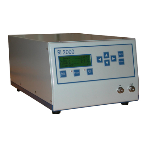
Alltech ELSD 2000 User manual

Table of Contents
1. INTRODUCTION
1.1 About the ELSD 2000 ............................................................................................................................. 4
1.2 What Is Included with the ELSD 2000 .................................................................................................... 4
1.3 Principle of Operation ............................................................................................................................. 5
2. INSTALLATION
2.1 What You Will Need ................................................................................................................................ 6
2.2 Unpacking............................................................................................................................................... 6
2.3 Controls and Features ............................................................................................................................ 7
2.3.1 Front Panel .................................................................................................................................... 7
2.3.2 Left Side Panel .............................................................................................................................. 7
2.3.3 Right Side Panel ............................................................................................................................ 8
2.3.4 Rear Panel..................................................................................................................................... 8
2.4 Making Electrical and Fluid Connections................................................................................................ 9
3. INSTRUMENT CONTROL
3.1 ELSD 2000 Control Options ................................................................................................................. 12
3.2 Using the ELSD 2000 Control Panel .................................................................................................... 12
3.3 Navigating the Screens......................................................................................................................... 12
3.4 Powering Up ......................................................................................................................................... 13
3.5 Operation Screen.................................................................................................................................. 13
3.6 Instrument Status.................................................................................................................................. 13
3.6.1 Standby........................................................................................................................................ 13
3.6.2 Run .............................................................................................................................................. 13
3.7 Menu Screen ........................................................................................................................................ 14
3.8 Setting Up a Run .................................................................................................................................. 14
3.9 Method Screen ..................................................................................................................................... 15
3.10 Method Options .................................................................................................................................... 15
3.10.1 Select a Previously Saved Method ............................................................................................ 15
3.10.2 Edit an Existing Method ............................................................................................................. 16
3.10.3 Create a New Method................................................................................................................ 17
3.11 Configuration Screen ............................................................................................................................ 17
1

3.12 Configuration Options............................................................................................................................ 18
3.12.1 Set Audio Alarm .......................................................................................................................... 18
3.12.2 Select Full-Scale Voltage............................................................................................................ 18
3.12.3 Set Fault Relay Override ............................................................................................................ 18
3.13 Diagnostics ............................................................................................................................................ 18
4. ROUTINE OPERATION
4.1 Safety .................................................................................................................................................... 18
4.2 Operation Notes .................................................................................................................................... 19
4.3 Important Operating Parameters ........................................................................................................... 19
4.4 Selecting Initial Operating Conditions.................................................................................................... 21
4.4.1 Selecting Initial Conditions for Impactor ‘Off’ Mode...................................................................... 21
4.4.2 Selecting Initial Conditions for Impactor ‘On’ Mode...................................................................... 22
4.5 Start-Up Sequence ................................................................................................................................ 23
4.6 Shutdown Sequence ............................................................................................................................. 24
4.7 Optimization Procedure ......................................................................................................................... 24
4.7.1 Optimization for Impactor‘Off’ Mode ............................................................................................ 24
4.7.2 Optimization for Impactor ‘On’ Mode ............................................................................................25
5. DIAGNOSTICS AND TROUBLESHOOTING
5.1 Operation Error Messages .................................................................................................................... 26
5.2 Diagnostics Options............................................................................................................................... 27
5.3 Performing Diagnostic Tests.................................................................................................................. 27
5.3.1 Optics Test.................................................................................................................................... 27
5.3.2 Nebulizer Gas Pressure Test........................................................................................................ 28
5.3.3 Flow Meter Test ............................................................................................................................ 29
5.3.4 Communication Test ..................................................................................................................... 30
5.4 Manual Control Screen.......................................................................................................................... 31
5.5 Error Log................................................................................................................................................ 31
5.6 Diagnosing Baseline Noise.................................................................................................................... 32
5.7 Troubleshooting Charts ......................................................................................................................... 33
2

6. APPENDICES
6.1 Specifications ........................................................................................................................................ 36
6.2 Replacement Parts ................................................................................................................................ 36
6.3 Contact Information ............................................................................................................................... 36
6.4 Volatile Mobile Phase Modifiers............................................................................................................. 37
6.5 ELSD 2000 Cleaning Procedures.......................................................................................................... 38
6.5.1 Drift Tube Cleaning Procedure ..................................................................................................... 38
6.5.2 Nebulizer Cleaning Procedure...................................................................................................... 38
6.6 Power Module Adjustments................................................................................................................... 39
6.6.1 Changing the Input Voltage .......................................................................................................... 39
6.6.2 Fuse Replacement ....................................................................................................................... 39
6.7 Warranty, Returns, and Repairs ............................................................................................................ 40
6.8 Useful References ................................................................................................................................. 41
3

1.2 WHAT IS INCLUDED WITH THE ELSD 2000
The ELSD 2000 shipping container should contain the
following:
• ELSD 2000 Detector
• Operating Manual
• Power Cord
• Signal Cable
• Tools:
Open-End Wrench, 3/8'' x 7/16''
Open-End Wrench, 1/4'' x 5/16''
Hex Ball Driver, 3/32'' (long)
Hex Ball Driver, 3/32'' (short)
Drift Tube Cleaning Brush
• Replacement Fuses:
3A and 6A (1 ea.)
• Flex Connect PEEK Tubing, 6'' x 0.005'' ID
• Nebulizer Gas Supply Line:
Teflon® Tubing, 50' x 1/8'' ID
1/8'' Parker Brass Nut and Ferrule*
• Drain Collection Materials:
Tygon®Drain Tubing, 4' x 3/8'' OD
Drain Waste Bottle with Lid, 500mL
3/8'' Parker Stainless Steel Nut and Teflon® Ferrule*
• Exhaust Trap Kit:
Exhaust Tubing
Collection Flask with Stopper, 500mL
Exhaust Elbow
Lead Ring
• ELSD 2000 PC Control Software**
CD-ROM
RS-232 Cable
Operating Manual
* The detector is shipped with these parts attached to their
respective ports.
**NOTE: The ELSD 2000 Detector must contain a
compatible EPROM chip to be functional with
the PC control software. Consult the
ELSD 2000 Control Software Manual for
further details.
Refer to Section 6.2, Replacement Parts, for part numbers if
replacement parts are needed.
1. INTRODUCTION
1.1 ABOUT THE ELSD 2000
The Alltech ELSD 2000 (Evaporative Light Scattering
Detector) is designed for use with High Performance Liquid
Chromatography (HPLC) systems to analyze any compound
that has sufficiently lower volatility than the mobile phase.
Some of its possible application areas include the analysis of
carbohydrates, pharmaceuticals, lipids, triglycerides,
underivitized fatty and amino acids, polymers, surfactants,
nutraceuticals, and combinatorial libraries.
Evaporative light scattering detection eliminates the common
problems associated with other HPLC detectors. RI detection
can be complicated by solvent front interferences, baseline
instability due to extreme temperature sensitivity, and
incompatibility with gradients. RI can also have a less
sensitive response than ELSD’s. Low-wavelength UV can
suffer baseline drift when using steep gradients and also
requires that the analyte have a chromophore. The ELSD is
not plagued by these limitations. Unlike these other detectors,
the ELSD can achieve stable baselines with multisolvent
gradients for improved resolution and faster separations.
Also, since the ELSD response does not depend on the
sample’s optical characteristics, the sample does not require
a chromophore or fluorophore for detection.
The ELSD 2000 offers the most advanced evaporative light
scattering detection technology available. The nebulizer has
been redesigned for increased ruggedness. Digital gas flow
control allows you to adjust flowrate directly from the front
panel or remotely via PC. You now have the option to select
from two modes of operation: Impactor ‘On’ and Impactor
‘Off’. Impactor ‘Off’ mode is ideal for analyzing non-volatile
compounds with highly organic mobile phases or with highly
aqueous/low flowrate (1.0mL/min or less) mobile phases.
This mode maximizes sensitivity for these applications by
sending the entire sample stream to the optical cell for
detection. Impactor ‘On’ mode is best for analyzing non-
volatile compounds with higher flowrate or highly aqueous
mobile phases (up to 5.0mL/min, including steep gradients),
and for analyzing semi-volatile compounds. In Impactor ‘On’
mode, larger droplets in the aerosol are removed, so optimum
mobile phase evaporation can be obtained at significantly
lower drift tube temperatures. Only the ELSD 2000 offers
dual-mode operation, which allows you to maximize sensitivity
and baseline stability for all possible mobile phases and
analytes.
Several instrument control options are available for the ELSD
2000. Instrument parameters can be displayed and controlled
directly through the front panel using membrane-based screen
keys and a numeric keypad. Built-in software provides an
intuitive series of screens for storing and editing up to ten
methods; configuring audio alarm, fault relay, and full-scale
voltage settings; and performing diagnostic tests and
troubleshooting functions. The ELSD 2000 can also be PC
controlled using the software included with the unit or
AllChrom™Plus software (sold separately, contact Alltech for
details).
4

1.3 PRINCIPLE OF OPERATION
The unique detection principle of evaporative light scattering
detectors involves nebulization of the column effluent to form
an aerosol, followed by solvent evaporation in a heated drift
tube, and then detection of the remaining non-volatile solute
particles in the light scattering cell.
Lower mobile phase flowrates require lower gas flowrates for
proper nebulization. Substitution of a 2.1mm ID column for
your standard 4.6mm ID column will allow you to greatly
reduce the mobile phase flowrate while also increasing the
sensitivity of the analysis.
Evaporation
Evaporation of the volatile components in the aerosol occurs
in the heated stainless steel drift tube. The proper drift tube
temperature setting for an application will depend on mobile
phase composition and flowrate, and on sample volatility.
Highly organic mobile phases require lower drift tube
temperatures for evaporation than highly aqueous mobile
phases. Lower mobile phase flowrates require lower drift
tube temperature than higher mobile phase flowrates. Semi-
volatile analytes require the use of much lower drift tube
temperatures to obtain optimum sensitivity. The optimum
temperature should be determined by observing the signal-
to-noise ratio with respect to temperature.
In order to provide optimum sensitivity for all applications,
the ELSD 2000 is designed to operate in two different modes
(patent pending). Depending on the application, the Teflon®-
coated stainless steel impactor is placed either parallel
(Impactor ‘Off’ mode) or perpendicular (Impactor ‘On’ mode)
to the flow path of the aerosol. In the Impactor ‘Off’ mode,
the impactor does not disturb the flow of the aerosol as it
travels through the drift tube. This allows the entire sample
stream to reach the optical cell for maximum sensitivity. This
mode is best for analyzing non-volatile compounds and/or
compounds separated using volatile (mostly organic) mobile
phases. In the Impactor ‘On’ mode, the aerosol contacts the
impactor and larger droplets exit through the drain tube. The
remaining droplets pass around the impactor and travel
through the drift tube. The Impactor ‘On’ mode is best for
analyzing semi-volatile analytes or for analyzing compounds
separated using high flowrates (up to 5.0mL/min, including
steep gradients) and/or highly aqueous mobile phases.
Nebulization
Evaporation
Detection
Nebulization
The column effluent from an HPLC separation enters the
nebulizer, where it is mixed with a steady stream of nebulizing
gas (usually nitrogen) to form an aerosol. The aerosol consists
of a uniform distribution of droplets whose size is dependent
on the gas flowrate used for the analysis. The lower the gas
flowrate, the larger the resulting droplets will be. Larger
droplets scatter more light and increase the sensitivity of the
analysis, but they are also more difficult to evaporate in the
drift tube. There will be an optimum gas flowrate for each
method which will produce the highest signal-to-noise ratio.
Non-volatile impurities in the mobile phase or nebulizing gas
will produce noise. Using the highest quality gas, solvents,
and volatile buffers (preferably filtered) will greatly reduce
baseline noise. Noise will also increase if the mobile phase
has not been completely evaporated. Detector settings must
be carefully selected to ensure adequate mobile phase
evaporation.
Detection
The sample particles emerge from the drift tube in the mobile
phase vapor and enter the light scattering cell. In the optical
cell, the sample particles scatter light emitted by a laser light
source while the evaporated mobile phase does not. The
scattered light is detected by a silicon photodiode, generating
a signal that is sent to the analog output for data collection.
5

• Solvent reservoirs, tubing, inlet filters, paper,
pens, etc. required for pump and data system
operation. Consult the appropriate manuals
for requirements.
NOTE: Only volatile buffers may be used in the mobile
phase. Mobile phases containing buffers
should be filtered to prevent noise. Refer to
Section 6.4, Volatile Mobile Phase Modifiers,
for a list of suitable buffers.
2.2 UNPACKING
The ELSD 2000 detector and its accessories are shipped in
the same container. Unpack components carefully, making
sure all items on the packing list have been included and are
in good condition. Save the container and packing material
for future use.
The ELSD 2000 has been carefully shipped to ensure that it
is received in proper condition. Any damage to the container
or its contents should be reported immediately to your local
distributor or to Alltech Associates. Please refer to Section
6.7, Warranty, Returns, and Repairs, for more information.
2. INSTALLATION
2.1 WHAT YOU WILL NEED
In addition to the ELSD 2000 detector and its accessories,
you will need the following for installation of a complete
chromatographic system:
Exhaust System:
• A fume hood or other ventilation device located
close to the detector to remove the detector
exhaust from the laboratory. Use only the
exhaust trap kit provided with the detector.
Gas Supply:
• A supply of clean, dry nebulization gas, preferably
nitrogen, regulated from 65 to 80 psig. 99.9%
purity or better is recommended. This can
be a high pressure gas cylinder, a high pressure
liquid tank, or a nitrogen generator.
HPLC System Components:
• An HPLC pump, isocratic or gradient, capable of
low-pulsation solvent delivery at a flowrate ranging
from at least 0.1 to 1.5mL/min against pressures of
at least 3,000 psig. Lower flowrate capabilities may
be necessary for microbore columns.
• An autosampler or manual injection valve.
• A column capable of separating the compounds of
interest. If you are uncertain which column to use,
contact your Alltech representative or the Alltech
Technical Support Group for assistance (Phone:
1-800-33-SOLVE).
• A guard column or cartridge compatible with the
separation column is recommended to prolong
separation column lifetime.
• A column heater, if needed.
• A data system, integrator, or stripchart recorder
capable of accepting analog voltage data. 0-10mV
or 0-1000mV systems can be used.
Other:
• HPLC-grade mobile phase solvents.
6

Set Read
Tube Temp: 30.0 30.0 °C
Gas Flow: 2.0 2.0 L/min
Gain: 2
Impactor: On
METHOD: A OUTPUT mV
1000mV/FS
0.5
[Edit] [Menu] [Standby] [Zero]
2.3 CONTROLS AND FEATURES
1. LCD (Liquid Crystal Display): The main screen displayed
on the LCD panel during use of the instrument is the Operation
screen. The Operation screen lists instrument status and
parameters such as method name, drift tube temperature,
gas flowrate, impactor position, gain, signal output, full-scale
voltage setting, and the total number of operation errors
occurring (if any). The LCD panel also displays all screens
related to method, configuration, and diagnostic functions.
All instrument parameters for the ELSD 2000 can be displayed
and controlled through the front panel:
2. Numeric Keypad: Membrane-based keypad provides
values 0 through 9, ‘ * ’ (asterisk), and ‘Enter’ for adjusting
instrument parameters.
3. Screen Keys: Four circular, membrane-based screen
keys are located on the front panel. The function of each key
is screen-dependent, with its current function listed
immediately above it on the LCD panel if the key is active in
that screen.
2.3.2 LEFT SIDE PANEL (Figure 2.2)
1.Liquid Inlet: The column effluent tubing connects to the
LIQUID INLET with a 1/16” male fingertight fitting.
2.Gas Inlet: The GAS INLET consists of a 1/8" CPI
Parker fitting that accepts the nebulizer gas supply line.
LIQUID
INLET GAS
INLET
12
2
3
1
2.3.1 FRONT PANEL (Figure 2.1) Figure 2.1
Figure 2.2

2.3.3 RIGHT SIDE PANEL (Figure 2.3)
1. Drain: The DRAIN bulkhead accepts 3/8" OD Tygon®
tubing which is then extended into the 500mL drain waste
container provided.
2.3.4 REAR PANEL (Figure 2.4)
1. Power Module: Contains a socket for the incoming
power cord, which can be adjusted to a voltage of 120V (US
standard) or 240V (European Standard). It also contains the
main power switch, which is used to turn the system power
On/Off, and the line fuse.
2. Twelve-Pin Connector: Outputs TTL/contact closure
signals or accepts signals from peripheral equipment. Only
pins 1 through 7 currently have programmed functions.
CAUTION: Operation at the wrong input voltage may
damage the detector. Refer to Section 6.6, Power
Module Adjustments, for details on changing the
voltage setting and line fuse. The fuse value will
depend on the line voltage (6A for 120V, 3A for 240V).
DRAIN
1
-+-+NOCNC
RS 232
OUTPUT
Alltech Associates, Inc.
2051 Waukegan Rd.
Deerfield, IL 60015
1
2
3
5
4
6
Remote
Gas Auto
Zero Fault
Relay
123456789101112
Remote Gas Autozero Fault Relay
NO C NC
-+-++-+
1234567
Figure 2.3
NOTE: The waste container must ALWAYS contain
enough liquid to cover the end of the drain
tube during operation of the detector.
Otherwise, nebulizer gas may escape through
the drain tube, causing improper nebulization.
Figure 2.4
8

Remote Gas Control: Pin 1: Ground (-) Pin 2: Signal (+)
A momentary TTL/contact closure input signal
toggles the gas supply solenoid On/Off.
Autozero: Pin 3: Ground (-) Pin 4: Signal (+)
A momentary TTL/contact closure input signal
activates the autozero. It mimics the function
of the [Zero] key.
Fault Relay: Pin 5: Normally Open (NO ) (+)
Pin 6: Common (-)
Pin 7: Normally Closed (NC) (+)
Outputs a TTL/contact closure signal to shut down
pump flow when any operation error occurs on the
detector. Normally Open (NO) or Normally Closed
(NC) will be used, depending on the instrument.
3. RS-232 Port: An RS-232 cable is connected to this port
for PC control of the ELSD 2000. PC control will also require
the use of either the ELSD 2000 Control Software included
with the unit or AllChrom™Plus software (sold separately,
contact Alltech for more information).
4. Exhaust Outlet: Nebulizer gas, mobile phase vapor,
and solute mist or particles produced during an analysis
will exit the detector through this outlet. The exhaust outlet
accepts the provided exhaust tubing, which must then be
connected to the exhaust trap kit and a fume hood.
5. Signal Output: The signal cable is connected to the
OUTPUT on the rear panel of the detector and is used to
send analog signal to your data collection device.
6. Fan: Provides cooling airflow through the instrument.
Do not block.
NOTE: Use of the fault relay override will prevent
the pump flow from being shut down when
errors occur on the detector. Refer to section
3.12.3, Set Fault Relay Override, for more
information.
2.4 MAKING ELECTRICAL AND FLUID
CONNECTIONS
1. Unpacking the Unit: Remove the ELSD from its shipping
container and position it near the column outlet of your HPLC
system and the fume hood. Make sure there is free flow of
air to the bottom of the ELSD and to the cooling fan at the
rear panel of the ELSD. Allow the detector to warm to
ambient temperature if necessary. Save the shipping
container for future use.
2. Power Connection: Plug the power cord provided with
the unit into the power module on the rear panel of the
detector. Make sure the unit is set to the proper voltage.
The voltage is field selectable for operation at 120V (US
standard) or 240V (European Standard).
3. Gas Connection: Connect the gas supply (preferably
nitrogen) to the GAS INLET on the left side panel. Gas
supply should be regulated from 65 to 80 psig. This inlet
accepts a 1/8” CPI Parker fitting. A stable gas flow and
pressure are necessary for reproducible results. The gas
must be free of contaminants, such as oil, water, particulates,
or any other non-volatile substances. A 0.1µm gas filter is
built into the instrument.
4. Liquid Connection: Connect the column effluent line to
the LIQUID INLET with a 1/16" male fitting. The ID and
length of the tubing between the column and the detector
should be kept as small as possible to avoid band broadening.
We recommend 0.005" ID tubing for best results.
5. Drain Setup: Using tubing cutters, cut an appropriate
length of 3/8" OD Tygon®tubing to be used in the drain
setup. Attach the tubing to the DRAIN outlet on the right side
panel using the stainless steel nut and Teflon®ferrule attached
to the drain port. Submerge the drain tube into a drain
collection container filled with enough liquid (water initially)
to cover the end of the tube and secure with the lid to prevent
solvent fumes from escaping. Use the 500mL waste container
provided at bench level, or use a larger container at floor
level (with drain tube submerged in liquid) for longer or
overnight runs. Monitor the liquid level in the drain collection
container during Impactor ‘On’ applications, and decant
excess liquid when the level approaches the top of the
container.
CAUTION: Operation at the wrong input voltage may
damage the detector. Refer to Section 6.6.1,
Changing the Input Voltage, for details on adjusting
the voltage setting.
CAUTION: The liquid level in the drain container must
remain lower than the level of the nebulizer for proper
drainage and detector operation. To ensure this, only
the 500mL waste container provided may be used at
bench level. A larger container may be substituted for
longer and/or unattended (i.e. overnight) runs but it
must be placed at floor level.
9

CAUTION: The liquid level in the drain container must
be monitored during Impactor ‘On’ mode, and excess
liquid should be removed when the level approaches
the top of the container. When removing excess liquid,
remember to leave enough liquid in the container so
the drain tubing remains submerged. There is no
need to monitor liquid levels during Impactor ‘Off’
mode because no liquid drains during this mode.
CAUTION: Do not allow the drain container to
completely fill during operation as this will cause
spillage and/or improper drainage.
Figure 2.5
7. Signal Output: Connect a signal cable from your data
collection device to the OUTPUT port on the rear panel of the
detector.
8. RS-232 Connection: Connect the RS-232 cable from
the RS-232 port on the rear panel of the detector to the PC or
the AllChrom™interface box. Refer to the appropriate manual
for further instructions.
6. Exhaust Connection: Connect the exhaust elbow
provided to the EXHAUST outlet on the rear panel of the unit.
Extend the exhaust tubing from the elbow to the condensation
trap. The tubing should permit continuous downward flow of
any condensate into the collection flask. The lead ring
provided can be placed on the collection flask for stability.
Connect the additional piece of exhaust tubing to the
condensation trap and direct to a fume hood or other
ventilation system. There should be no low spots in the
tubing where condensate can collect. If necessary, the
exhaust tubing can be shortened by cutting with a razor to
the desired length. See Figure 2.5 below.
Should Be Emptied
When Half Full
Lead Ring
Exhaust Elbow
Recommended Set-Up for Exhaust Trap and Drain Collection
To Fume Hood
Or Vent System
No Low Spots
Bench Level
ELSD
2000
DRAIN
10

Autozero: Pin 3: Ground (-)
Pin 4: Signal (+)
Pins 3 and 4 on the ELSD 2000 can accept a TTL/contact
closure signal from a start signal cable to autozero the detector
after each injection. This signal is typically sent from an
autosampler or a manual injection valve with a position-
sensing switch. Consult the appropriate manuals for wiring
information.
Fault Relay: Pin 5: Normally Open (NO) (+)
Pin 6: Common (-)
Pin 7: Normally Closed (NC) (+)
Pins 5, 6, and 7 on the ELSD 2000 can output a TTL/contact
closure signal to stop pump flow whenever an operation
error occurs on the detector. Consult the appropriate manuals
for wiring details.
NOTE: The fault relay override function can be used
to temporarily disable the fault relay without
disconnecting the wiring. Refer to Section
3.12.3, Set Fault Relay Override, for more
details.
9. 12-Pin Connections: Make connections to the 12-pin
terminal strip on the rear panel of the detector depending on
which of the following functions are needed:
Remote Gas Control: Pin 1: Ground (-)
Pin 2: Signal (+)
Pins 1 and 2 on the ELSD 2000 can accept a TTL/contact
closure signal to turn gas flow on/off. It is especially useful
for turning off gas flow at the end of a run. This signal is
typically sent from an autosampler or a data collection system.
Consult the appropriate manuals for wiring information.
11

3. INSTRUMENT CONTROL
3.1 ELSD 2000 CONTROL OPTIONS
The ELSD 2000 may be controlled either directly through the
front panel or remotely using a PC.
NOTE: Only the ELSD 2000 PC Control software
included with the unit or AllChrom™ Plus
software can be used for PC control of the
ELSD 2000. The ELSD 2000 is not compatible
with any other PC control software.
This section of the manual describes operation of the ELSD
2000 directly through the front control panel. For details on
PC control of the ELSD 2000, please consult the ELSD 2000
Control Software Manual for instructions.
3.2 USING THE ELSD 2000 CONTROL PANEL
The ELSD 2000 can be controlled directly from the front
control panel using the screen keys, numeric keypad, and
LCD display. Refer to Section 2.3.1, Front Panel, for a
diagram and more details.
3.3 NAVIGATING THE SCREENS (Figure 3.1)
Figure 3.1
Audio
Alarm Full-Scale
Voltage Fault Relay
Override
Select
Method Edit
Method
Method Diagnostics
Configuration
Welcome Screen
Operation Screen
Edit Method Menu
Diagnostic
Tests Manual
Control Error Log
Optics
Test Nebulizer
Gas Pressure
Test
Flow Meter
Test Communication
Test
12

3.6.2 RUN
In ‘Run’ mode, the laser, gas flow, and drift tube heaters are
turned on and impactor position will match its setpoint. The
signal output will now be displayed. The Operation screen
will display signal output in mV, and screen key options
[Edit], [Menu], [Standby], and [Zero] will be available.
NOTE: Press ‘Enter’ at any time from the Operation
screen to list error messages. Refer to Section
5.1, Operation Error Messages, for error
message descriptions and solutions.
3.6 INSTRUMENT STATUS
The ELSD 2000 has two different operational states:
‘Standby’ and ‘Run’. Current status of the instrument is
displayed on the Operation screen:
3.6.1 STANDBY
The detector enters ‘Standby’ mode immediately after
powering up. In this mode, the laser, gas flow, and drift tube
heaters are turned off. The Operation screen will display a
‘Standby’ message with a timer indicating how long the
instrument has been in this state. Screen key options are
[Menu] and [Run].
Operation Screen in ‘Standby’ Mode
METHOD: ABC OUTPUT mV
Set Read
Tube Temp: 70.0 23.4 oC
Gas Flow: 1.9 0.0 L/min Standby
Gain: 1 00:30:23
Impactor: Off 1000mV/FS
[Menu] [Run]
3.4 POWERING UP
The ELSD 2000 is powered up using the power switch on the
rear panel of the instrument. A Welcome screen will appear
briefly on the display panel once the unit has been turned on:
3.5 OPERATION SCREEN
The Operation screen is the main screen displayed during
use of the instrument. This screen provides the following
information for the currently loaded method:
• Method: Currently loaded method name.
• Tube Temp: Setpoint and current reading of the
drift tube temperature in oC.
• Gas Flow: Setpoint and current reading of the
nebulizer gas flowrate in L/min.
• Gain: Current gain setting. Possible values are 1,
2, 4, 8, and 16. A gain setting of 1 produces an
unamplified signal, and each gain increase will produce
a twofold signal amplification over the previous value.
• Impactor: Current position of the impactor. Either ‘Off’
or ‘On’ depending on your application.
• Output: The signal output in mV is displayed when
the instrument is in ‘Run’ mode. A ‘Standby’ message
with time elapsed is displayed when the instrument is
in ‘Standby’ mode.
• Full-Scale Voltage: Full-scale voltage setting. Either
10mV or 1000mV, depending on the data collection
system used.
• Total Errors: The total number of operation errors
currently occurring on the instrument (if any).
• Screen Keys: Used to change instrument status or to
access functions from other screens.
[Edit]: Shortcut that takes you directly from the ‘Run’
screen to the <<Edit Method>> screen.
[Menu]: Brings up the <<Menu>> screen from either
the Standby or ‘Run’ screens.
[Standby]: Puts the instrument into ‘Standby’ mode
from the ‘Run’ screen.
[Zero]: Autozeros the signal output from the ‘Run’
screen.
[Run]: Runs the currently loaded method settings,
taking the unit out of ‘Standby’ mode.
Operation Screen in ‘Run’ Mode
METHOD: ABC OUTPUT mV
Set Read
Tube Temp: 70.0 70.3 oC
Gas Flow: 1.9 1.9 L/min
Gain: 1
Impactor: Off
Total Errors: 2 1000mV/FS
[Edit] [Menu] [Standby] [Zero]
3.4
ELSD 2000
Alltech Associates, Inc.
The Operation screen will then appear displaying a message
indicating the unit is in ‘Standby’ mode and a timer indicating
how long the instrument has been in this mode. The unit will
automatically display the settings for the last method that
was in use before shutdown.
13

3.7 MENU SCREEN
The <<Menu>> screen is accessed through the Operation
screen by pressing the [Menu] screen key. It offers the
following options:
3.8 SETTING UP A RUN
To set up a run you will need to:
1. Load the desired method.
Choose from the following method options:
• Select a previously saved method
• Edit an existing method
• Create a new method.
Refer to Section 3.10, Method Options, for details.
2. Configure the instrument.
Set the following non-method dependent parameters:
• Audio Alarm
• Full-Scale Voltage
• Fault Relay Override.
Refer to Section 3.12, Configuration Options,
for details.
1. Method: Brings you to the <<Method>> screen for method
options.
2. Configuration: Brings you to the <<Configuration>>
screen for configuration options.
3. Diagnostics: Brings you to the <<Diagnostics>> screen
for diagnostic options.
Press 1, 2, or 3 to select one of the above options.
Press [Exit] to return to the Operation screen.
<<Menu>>
1. Method
2. Configuration
3. Diagnostics
[Exit]
14

3.10 METHOD OPTIONS
3.10.1 SELECT A PREVIOUSLY SAVED METHOD
Press 1 from the <<Method>> screen to choose the Select
Press [Cancel] to cancel loading this method, and you will
return to the <<Method List>> screen with the original method
loaded.
Press [OK] to accept this method, and you will return to the
Operation screen with the new method loaded.
NOTE: After the new method is loaded, the instrument
will enter the Operation screen in the same
mode it was in prior to loading the method. If
the unit was in ‘Standby’ when the new method
was accepted, it will remain in ‘Standby’ until
you press [Run]. If the unit was in ‘Run’ mode
prior to loading the new method, the new
method will run immediately after loading the
new method.
<<Method List>>
0. METHOD A
1. METHOD B
2. METHOD C
3. METHOD D
4. METHOD E
[Menu] [More]
<< Confirmation>>
Number: 0
Name: METHOD A
Temperature: 70.0 °C
Gas Flow: 1.9 L/min
Gain: 1
Impactor: Off
[OK] [Cancel]
From the <<Method List>> screen, you may select from up to
ten previously saved methods. Method numbers 0 through 4
are displayed on the first screen. Press [More] to reach
method numbers 5 through 9. Press [More] again to return
to method numbers 0 through 4.
Press the number of the desired method, and a
<<Confirmation>> screen will appear:
3.9 METHOD SCREEN
Press 1 from the <<Menu>> screen to bring up the
<<Method>> screen. It offers the following options:
1. Select Method: Select from a list of up to ten previously
saved methods.
2. Edit method: Edit a previously existing method or create
a new method.
Press 1 or 2 to select one of the above options.
Press [Menu] to return to the <<Menu>> screen.
<<Method>>
1. Select Method
2. Edit Method
[Menu]
Method option. This will bring up the <<Method List>>
screen:
15

Press [OK] to accept the new name, and the <<Edit
Method>>screen will appear with the new method
name listed.
Press [Cancel] to reject the new name, and the <<Edit
Method>> screen will reappear with the original
name intact.
<<Confirmation>>
New Name: METHOD A
[OK] [Cancel]
3.10.2 EDIT AN EXISTING METHOD
Methods are edited through the <<Edit Method>> screen.
To access this screen:
1. Press 2 from the <<Method>> screen, OR
2. Press [Edit] from the Operation screen while
in ‘Run’ mode.
The <<Edit Method>> screen will display the currently loaded
method:
<<Edit Method>>
1. Method Number: 0
2. Method Name: METHOD A
3. Tube Temp: 70.0 °C
4. Gas Flow: 1.9 L/min
5. Gain: 1
6. Impactor: Off
[Cancel] [Menu] [Save] [Run]
<<Edit Name>>
Press Enter when name is completed.
Name:
ABCDEFGHIJKLMNOPQRSTUVWXYZ 1234567890
[<=] [=>] [Accept] [Back]
Use the arrow keys to move the cursor to the desired letter,
number, or space (position between Z and 1). Press [Accept]
to select a character. Press [Back] to remove the most
recently selected character. Method names can contain up
to 18 characters (numbers, letters, and spaces). Press ‘Enter’
when you have completed the method name, and a
<<Confirmation>> screen will appear:
Press the number corresponding to the parameter you want
to change:
1. Method Number: Press 1 to change the method number,
and the current value will flash. Select the new method
number, using any number between 0 and 9. Press ‘Enter’
to accept, and the new value will be listed in the method, or
press ‘ * ’ (asterisk) to cancel the change, and the original
value will return in the method.
2. Method Name: Press 2 to change the method name.
This will bring up the <<Edit Name>> screen:
3. Tube Temperature: Press 3 to change the drift tube
temperature, and the current setpoint will flash. Enter the
new temperature setting using the numeric keys. The
allowable drift tube temperature range is 25°- 120oC. Press
‘Enter’ to accept, and the new setpoint will be listed in the
method; or press ‘ * ’ (asterisk) to cancel the change, and the
original setpoint will return in the method.
4. Gas Flow: Press 4 to change the gas flowrate, and the
current setpoint will flash. Enter the new gas flowrate using
the numeric keys. Gas flowrates from 0 to 4.0L/min are
allowed and values outside of this range will not be accepted.
Press ‘Enter’ to accept the change, and the new value will
be listed in the method, or press ‘ * ’ (asterisk) to cancel the
change, and the original value will return in the method.
5. Gain: Press 5 to change the gain setting, and the current
setpoint will flash. Press 5 repeatedly until the desired value
is displayed, from a choice of 1, 2, 4, 8, or 16. Press ‘Enter’
to accept the change, and the new value will be listed in the
method, or press ‘ * ’ (asterisk) to cancel the change, and the
original value will return solidly in the method. Each increase
in gain value will produce a twofold signal amplification over
the previous value.
6. Impactor: Press 6 to change the impactor position, and
the current setting will flash. Press 6 to toggle between the
‘Off’ and ‘On’ positions until you reach the desired setting.
Press ‘Enter’ to accept the change, and the new setpoint will
be listed in the method; or press ‘ * ’ (asterisk) to cancel the
change, and the original setpoint will return in the method.
16
A

Cancelling Method Changes
Press [Cancel] from the <<Edit Method>> screen to cancel
ALL method changes made in the current editing session,
and you will return to the <<Menu>> screen with the original
method settings intact.
Saving Method Changes
You may press [Save], [Run], or [Menu] from the <<Edit
Method>> screen to activate the method change(s):
Press [Save] to permanently save these changes to the
method. The Operation screen will then appear with the new
settings.
Press [Run] to make temporary changes to the method.
The Operation screen will then return with the new settings
listed, and the method name will now have an asterisk in
front of it to indicate that the changes are temporary.
Temporary changes will not be saved if the method is reloaded
or if the unit has been powered off and on.
Press [Menu] to permanently save these changes to the
method and then go directly to the <<Menu>> screen. Refer
to Section 3.7, Menu Screen, for details on using the
<<Menu>> screen.
3.10.3 CREATE A NEW METHOD
Create a new method by saving the new method name,
number, and parameter settings over a previously existing
method. Follow the instructions in Section 3.10.2, Edit an
Existing Method.
3.11 CONFIGURATION SCREEN
Press 2 from the <<Menu>> screen to access the
<<Configuration>> screen.
1. Audio Alarm: Set audio alarm. If activated, an
audio alarm will sound whenever an operation error occurs
on the instrument.
2. Full-Scale Voltage: Set full-scale voltage
to either 10mV or 1000mV, depending on your data
collection system.
3. Fault Relay Override: Set the fault relay override. In the
‘On’ position, the fault relay will be disabled and the pump
flow will not shut down when operation errors occur. In
the ‘Off’ position, the fault relay is active. This function is
useful during equilibration and method optimization.
Press 1, 2, or 3 to select one of the above options.
Press [Menu] to return to the <<Menu>> screen.
<<Configuration>>
1. Audio Alarm: Off/On
2. Full-Scale Voltage: 10mV/1000mV
3. Fault Relay Override: Off/On
[Menu]
17

3.12 CONFIGURATION OPTIONS
3.12.1 SET AUDIO ALARM
Press 1 on the <<Configuration>> screen to toggle the audio
alarm between the ‘Off’ and ‘On’ settings until you reach the
desired setting.
In the ‘On’ position, the audio alarm will be triggered whenever
operation errors occur on the detector while it is in the ‘Run’
mode. The error(s) must be remedied in order to deactivate
the alarm. The total number of errors is displayed on the
operation screen, and error details can be checked by
pressing ‘Enter’.
In the ‘Off’ position, the audio alarm will not be triggered
when operation errors occur.
3.12.2 SELECT FULL-SCALE VOLTAGE
Press 2 on the <<Configuration>> screen to toggle between
the 10mV and 1000mV full-scale voltage settings until you
reach the desired setting. The correct setting will depend on
the data collection system that is used.
If output exceeds 999.9mV, signal output will read ‘HI’. If
output drops below -99.9mV, signal output will read ‘LO’.
3.12.3 SET FAULT RELAY OVERRIDE
Press 3 from the <<Configuration>> screen to toggle between
the ‘Off’ and ‘On’ settings for the fault relay override until you
reach the desired setting.
In the ‘On’ position, the fault relay function will be disabled,
and operation errors will not turn off the pump flow. This
feature is useful when you want to change operating
conditions and do not want to trigger the fault relay while the
instrument equilibrates.
In the ‘Off’ position, the fault relay will be active, and the
pump flow will be stopped whenever an operation error occurs
on the ELSD 2000.
3.13 DIAGNOSTICS
Refer to Section 5, Diagnostics and Troubleshooting, for
information on using diagnostic functions.
4. ROUTINE OPERATION
4.1 SAFETY
7. USE FAULT RELAY to prevent operation of the ELSD
2000 under undesirable conditions.
Please use the following guidelines to insure safe operation
of the ELSD 2000:
1. KEEP LABORATORY WELL-VENTILATED to prevent
buildup of vaporized solvent.
2. USE A FUME HOOD or other ventilation device to
prevent the inhalation of any solvent fumes expelled
through the exhaust tube.
3. AVOID OPEN FLAMES AND SPARKS when using
flammable solvents.
4. USE AN INERT GAS, preferably nitrogen, to nebulize
mobile phases containing organic solvents.
5. DO NOT REMOVE THE COVER of the instrument
unless instructed to you by an Alltech representative.
6. ALWAYS POWER OFF before removing the cover.
DANGER: Avoid direct eye exposure to laser light.
CAUTION: Inside parts can be hot.
NOTE: The proper wiring must be connected for fault
relay to function. Refer to Section 2.4, Making
Electrical and Fluid Connections, for details.
NOTE: Detector can output a maximum of 2000mV,
as your data system permits.
18

4.3 IMPORTANT OPERATING PARAMETERS
Ideal performance of the ELSD 2000 is obtained by choosing
the best settings for an application. Nebulizer gas flowrate,
mobile phase flowrate, drift tube temperature, and impactor
position are parameters that must be optimized for best
results. The following paragraphs describe each parameter
and provide suggestions on selecting the proper settings:
1. IMPACTOR POSITION: The correct impactor position for
an application will depend on the mobile phase composition
and flowrate, and on the volatility of the analyte. Achieving
the proper balance between sensitivity and adequate mobile
phase evaporation is the key.
The Impactor ‘Off’ setting is best for the analysis of non-
volatile compounds with low flowrate/highly aqueous mobile
phases (1.0mL/min or less), or highly organic mobile phases.
This setting provides maximum sensitivity by allowing the
entire sample stream to reach the optical cell.
The Impactor ‘On’ setting is best for analyzing non-volatile
compounds with high flowrate/highly aqueous mobile phases,
and for the analysis of semi-volatile compounds. With the
Impactor ‘On’, a portion of the sample stream is diverted to
the drain tube. This results in adequate mobile phase
evaporation at flowrates up to 5.0mL/min, including steep
gradients. The Impactor ‘On’ setting is ideal for the analysis
of semi-volatile compounds because it allows the use of
significantly lower drift tube temperatures for greater
sensitivity.
NOTE: The Impactor ‘On’ setting should be used with
highly organic mobile phases only when the
analyte is semi-volatile. Otherwise, sensitivity
will be unnecessarily reduced.
The impactor position that you choose will greatly affect the
settings for all other parameters. See the following sections
for details.
NOTE: Only the 500mL drain container provided can
be positioned at bench level. Larger containers
must be placed at floor level.
2. Mobile phase should not be flowing when the drift tube
is not at proper vaporization temperature or when the
nebulizer gas is turned off. Otherwise you may get
liquid buildup in the drift tube.
3. IMPORTANT: Only volatile buffers are allowed in the
mobile phase. Non-volatile buffer particles will be viewed
as sample by the detector, causing unwanted baseline
noise. Refer to Section 6.4, Volatile Mobile Phase
Modifiers, for a list of suitable buffers.
4. Check the exhaust line and condensate trap daily.
Dispose of condensate, if necessary. Do not allow the
bottle to become full, as this will cause the exhaust gas
to bubble through the condensate, creating excess noise.
4.2 OPERATION NOTES
1. Monitor the liquid level in the 500mL drain waste
container during Impactor ‘On’ mode and remove excess
liquid when necessary. Or, submerge the drain tube in
a large container at floor level so that you do not have to
decant excess liquid as often. There is no need to
check the waste container during Impactor ‘Off’
applications, since no liquid will be draining.
2. NEBULIZER GAS FLOWRATE: The nebulizer gas
flowrate determines the size of the droplets formed during
nebulization. Higher gas flowrates produce smaller droplets,
which evaporate more easily than larger droplets. On the
other hand, smaller droplets scatter less light and therefore
will produce smaller signals than large droplets. You will
need to experiment to determine the gas flowrate that will
produce the best signal to noise ratio (S/N). Selection of the
proper gas flowrate will be largely dependent on your impactor
setting:
Impactor ‘Off’: The lowest possible gas flowrate needed for
effective nebulization will produce the largest signal. Refer
to Table 1 for the gas flowrate recommended for Impactor
‘Off’ applications.
19

Impactor ‘On’: The gas flowrates used for Impactor ‘On’
mode will generally be lower than flowrates used for Impactor
‘Off’ mode. Gas flowrates will usually be about 2.2L/min or
less for mobile phase flowrates of 1.0mL/min. Higher mobile
phase flowrates may require higher gas flowrates. If the gas
flowrate is set too high, more droplets will get past the
impactor then can be evaporated in the drift tube at that
temperature. This results in a noisy baseline. If the gas
flowrate is set too low, the droplets created will be too large
and there will be increased sample loss through impaction.
This results in decreased sensitivity. Refer to Section 4.7,
Optimization Procedure, for details on optimizing the gas
flowrate for Impactor ‘On’ applications.
3. MOBILE PHASE FLOWRATE:
Impactor ‘Off’: The Impactor ‘Off’ setting is effective for
highly organic mobile phases at flowrates up to 1.5mL/min,
and for highly aqueous mobile phases up to 1.0mL/min.
Higher mobile phase flowrates will require higher gas flowrates
and higher drift tube temperatures. It is therefore
advantageous to use the lowest possible mobile phase
flowrate.
Substitution of a smaller bore column for your standard 4.6mm
ID column will permit the use of lower solvent flowrates
without affecting retention times. For example, a flowrate of
0.2mL/min with a 2.1mm ID column is equivalent to a
1.0mL/min flowrate with a 4.6mm ID column. Smaller bore
columns will also provide an increase in sensitivity over
standard size columns due to decreased sample dilution.
Impactor ‘On’: The Impactor ‘On’ mode can be used with
mobile phase flowrates up to 5.0mL/min, including mobile
phases that are highly aqueous and/or have steep gradients.
Impactor ‘Off’: Aqueous solvents and volatile buffers require
higher drift tube temperatures than organic solvents for
evaporation. Higher mobile phase flowrates also require
higher drift tube temperatures than lower mobile phase
flowrates. Lower gas flowrates produce larger droplets and
therefore will require higher drift tube temperatures for mobile
phase evaporation. Drift tube temperatures for Impactor ‘Off’
mode are generally higher and have a greater range than
those used for Impactor ‘On’ mode. Refer to Table 1 for
recommended starting temperatures for Impactor ‘Off’ mode.
NOTE: If the drift tube temperature setting is too high,
a noisy baseline will result. The solvent can
boil in the nebulizer and cause poor
nebulization.
NOTE: When running a gradient, optimize the
parameters for the mobile phase portion which
is the most difficult to vaporize.
Impactor ‘On’: Impactor ‘On’ applications will require lower
drift tube temperatures than the Impactor ‘Off’ mode, generally
about 50°C or lower. A temperature of 40oC is usually
sufficient for evaporation of a highly aqueous mobile phase
at 1.0mL/min with a non-volatile analyte. Higher mobile
phase flowrates may require higher temperatures. Semi-
volatile compounds can be analyzed at even lower drift tube
temperatures for better sensitivity. If the drift tube temperature
is set too high, semi-volatiles may evaporate too readily. If
the drift tube temperature is too low, a noisy baseline will
result from inadequate evaporation of the mobile phase.
Ideally, you should use the lowest temperature that can
produce an acceptable, low-noise baseline without
compromising sensitivity. Refer to Section 4.4.2 for
information on selecting the proper drift tube temperature for
Impactor ‘On’ mode.
4. DRIFT TUBE TEMPERATURE: The proper drift tube
temperature setting will be based on mobile phase volatility
and flowrate, nebulizer gas flowrate, and analyte volatility.
Drift tube temperatures can be selected from 25°- 120oC in
1oincrements. The impactor setting you have selected for
your application will reflect these parameters:
20
Table of contents
Popular Security Sensor manuals by other brands

Lince
Lince 1597ZENITHDT Programming and operating manual

Metrohm
Metrohm 944 manual

Gas Clip Technologies
Gas Clip Technologies Multi Gas Clip Simple user manual

Lince
Lince JOLLY Programming and operating manual

PCB Piezotronics
PCB Piezotronics 482C24-SU Installation and operating manual

LEGRAND
LEGRAND Mosaic 0 489 22 manual