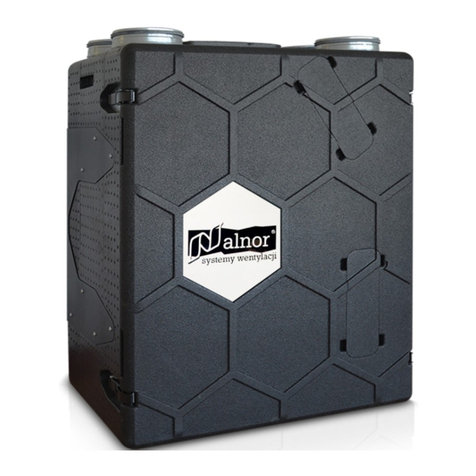
Alnor HRU-MinistAir-W-450 User manual

www.vent�lat�on-alnor.co.uk
Recovery vent�lators
HRU-M�n�stA�r-W-450
1

ALNOR
®
vent�lat�on systems
�s a legally protected trademark and techn�cal patent. All r�ghts reserved.
User’s manual of recovery vent�lators HRU-M�n�stA�r-W-450
Table of contenst
Safety Informat�ons......................................................................................................................................................3
Components.................................................................................................................................................................4
Techn�cal Data...............................................................................................................................................................5
Performance Curve......................................................................................................................................................6
Sound Curve..................................................................................................................................................................6
W�r�ng D�agram..............................................................................................................................................................7
Un�tD�mens�ons............................................................................................................................................................8
Serv�ce Space...............................................................................................................................................................8
Installat�on...................................................................................................................................................................8
SelectofElectr�calCableCross-Sect�on........................................................................................................................12
Control..........................................................................................................................................................................13
Ma�ntenance................................................................................................................................................................25
www.vent�lat�on-alnor.co.uk
2
Energy Label..............................................................................................................................................................26
Offer.............................................................................................................................................................................27

ALNOR
®
vent�lat�on systems
�s a legally protected trademark and techn�cal patent. All r�ghts reserved.
User’s manual of recovery vent�lators HRU-M�n�stA�r-W-450
!
ATTENTION
Safety �nformat�ons
• Th�s un�t has to be used under proper cond�t�ons accord�ng to �ts techn�cal spec�f�cat�on and
des�gn purpose. (Otherw�se respons�b�l�ty belongs to pract�t�oner.)
• Unauthor�zed personnel must not �nterfere �n un�t and/or must not use unor�g�nal spare parts.
(Otherw�se respons�b�l�ty of fa�lure that may occur belongs to pract�t�oner.)
• Do not �nstall th�s product �n a refr�gerated warehouse, heated sw�mm�ng pool or other
locat�on where temperature and hum�d�ty are s�gn�f�cantly d�fferent. (Fa�lure to heed th�s
warn�ng may result �n electr�cal shock or malfunct�on�ng.)
• Do not �nstall th�s product where �t w�ll be d�rectly exposed to ra�n. (Fa�lure to heed th�s
warn�ng may result �n electr�cal shock or malfunct�on�ng.)
• Do not �nstall th�s product �n a locat�on where ac�d, alkal� or organ�c solvent vapors, pa�nts or
other tox�c gases, gases conta�n�ng corros�ve components or h�gh concentrat�ons of o�ly
smoke are present. (Fa�lure to heed th�s warn�ng may result not only �n malfunct�on�ng but
also f�re, power leakage and electr�cal shock.)
• Do not use th�s product outs�de the range of �ts rated voltage and control capac�ty.
• Install th�s product �n an env�ronment where the the temperature ranges from 0 °C to +40 °C
and the relat�ve hum�d�ty �s less than 80%. If condensat�on �s expected to form,heat up the
fresh outs�de a�r by a duct heater etc.
• Select an adequately sturdy pos�t�on for �nstall�ng the product and �nstall �t properly and
securely.
• Use the des�gnated electr�cal w�res for the term�nal board connect�ons and connect the w�res
securely so that they w�ll not be d�sconnected. (Fa�lure to ensure proper co�nonnesc tmay
result �n f�re.)
• When pass�ng metal ducts through wooden bu�ld�ngs clad w�th metal laths, w�re laths or
metal, these ducts must be �nstalled �n such a way that they w�ll not make electr�cal contact
w�th metal laths, w�re laths or metal sheets. (Power leakage can cause �gn�t�on.)
• The outs�de ducts must be t�lted at a grad�ent (1/30 or more) downwards toward the outdoor
area from the ma�n un�t, and properly �nsulated. (The entry of ra�n water may cause power
leaks, f�re or damage to household property.)
• Gloves should be worn wh�le �nstallat�on. (Fa�lure to heed th�s warn�ng may result �n �njury.)
• A ded�cated c�rcu�t breaker must be �nstalled at the or�g�n of ma�ns power supply. Th�s c�rcu�t
breaker must be prov�ded w�th a means for lock�ng (lock and key).
• The body of the un�t, room control panel and cables keep away un�t 3 m. d�stance
• Th�s product must not be d�sassembled under any c�rcumstance. Only author�zed repa�r
techn�cans are qual�f�ed to conduct d�sassembly and repa�rs. (Fa�lure to heed th�s warn�ng
may result �n f�re, electr�cal shock or �njury.)
• Connect the product properly to the ground.(Malfunct�on�ng or power leaks can cause
electr�cal shock.)
• An �solator sw�tch hav�ng m�n�mum contact gap of 3 mm �n all poles must be prov�ded as
a means of d�sconnect�ng the power supply.
NOTE: The �nstallat�ons,wh�ch �s not ava�lable for �nstallat�on and operat�on manual, �s out of guarantee.
www.vent�lat�on-alnor.co.uk
3
PROHIBITED

www.vent�lat�on-alnor.co.uk
4
ALNOR
®
vent�lat�on systems
�s a legally protected trademark and techn�cal patent. All r�ghts reserved.
User’s manual of recovery vent�lators HRU-M�n�stA�r-W-450
Components
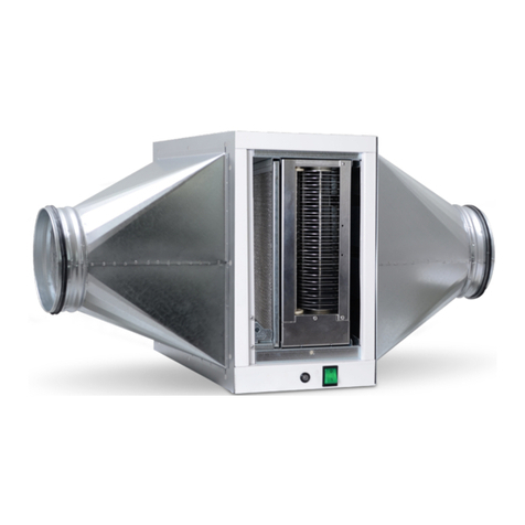
HRU-M�n�stA�r-W-450 un�ts are des�gned for recover�ng part of the energy of the exhausted a�r �n a vent�lat�on system. The
recovered energy �s d�rectly transferred to the suppl�ed fresh a�r, that reduce the necessary load on the a�r cond�t�on�ng system.
1
Control
Exhaust and Supply A�r F�ltres
By-Pass
Heat Recovery Exchanger
Cas�ng
Exhaust and Supply A�r Fans
1
2
3
4
5
6

ALNOR
®
vent�lat�on systems
�s a legally protected trademark and techn�cal patent. All r�ghts reserved.
User’s manual of recovery vent�lators HRU-M�n�stA�r-W-450
Techn�cal data
www.vent�lat�on-alnor.co.uk
5
SEC1
Average -37,41 A
Warm -12,67 E
Cold -76 A+
Typology B�d�rect�onal
Type of dr�ve Var�able speed
Heat recovery system Recuperat�ve
Thermal eff�c�ency %90,5
Max�mum flow rate (@0Pa) m³/h
m³/h
m³/s
450
Max�mum flow rate (@100Pa) 370
Electr�cal power �nput at max�mum flow W 169
Sound power level at reference flow rate Lwa57,3
Reference flow rate 0,072
Reference pressure d�fference Pa 50
SPI 2W/(m³/h)0.259
Control factor and typology 1/Manual
Declared leakage rates 0.3-Internal
0.4-External
M�x�ng rate %0
Pos�t�on and descr�pt�on of f�lter warn�ng www.ventilation-alnor.co.uk
Instruct�on of gr�lles www.ventilation-alnor.co.uk
Model HRU-MinistAir-W-450
Trade Mark ALNOR
Internet address www.ventilation-alnor.co.uk
A�r flow rate sens�v�ty N/R
Indoor/outdoor a�r t�ghtness N/R
AEC 3
Average 8.6
Warm 8.1
Cold 13.9
AHS 4
Average 46
Warm 20.8
Cold 89.9
¹ Specific Energy Consumption [kWh/(m².a)]
² Specific Power Input (W/(m³/h))
³ Annual Electricity Consumption [kWh electricity/a]
Annual Heating Saved [kWh primary energy/a]
*Technical data according to UE No. 1254/2014 (ErP).
4

www.vent�lat�on-alnor.co.uk
6
ALNOR
®
vent�lat�on systems
�s a legally protected trademark and techn�cal patent. All r�ghts reserved.
User’s manual of recovery vent�lators HRU-M�n�stA�r-W-450
Performance curve
Sound curve
External Pressure (Pa)
Air Volume (m3/h)
100 200 300
0
50
100
150
200
250
300
350
400
450
500
400 450 500350250150
Octave Sound Pressure Level (dB: Overall A Scale )
Central Frequency (Cycle per Second) Hz
dB
63 125 250 500 1000 2000 4000 8000
60
50
40
30
20
10 NR0 NR10
NR20
NR40
NR50
NR60
NR30
*Acoustic test is performed 1.5 meter away from the unit.

ALNOR
®
vent�lat�on systems
�s a legally protected trademark and techn�cal patent. All r�ghts reserved.
User’s manual of recovery vent�lators HRU-M�n�stA�r-W-450
W�r�ng d�agram
www.vent�lat�on-alnor.co.uk
7

www.vent�lat�on-alnor.co.uk
8
ALNOR
®
vent�lat�on systems
�s a legally protected trademark and techn�cal patent. All r�ghts reserved.
User’s manual of recovery vent�lators HRU-M�n�stA�r-W-450
Un�t d�mens�ons
610
V�ew from top
V�ew from front
V�ew from front
* All measurement values are mm.
* A clear space of 600 mm must be prov�ded �n front of the un�t for serv�ce.
710
725
797
160
min. 600 mm
RA
OA
EA
SA
Serv�ce space
Installat�on
EA - Exhaust A�r
SA - Supply A�r
OA - Outdoor A�r
RA - Return A�r
Installat�on Vers�on

ALNOR
®
vent�lat�on systems
�s a legally protected trademark and techn�cal patent. All r�ghts reserved.
User’s manual of recovery vent�lators HRU-M�n�stA�r-W-450
Installat�on
D�scharge Condensate Installat�on
Mo�sture condensed water should be dra�ned out of the un�t, to prevent water damage �n heat recovery un�t and ductwork system.
Follow�ng precaut�ons should be observed:
1. Condensate p�pe connect�ons to ma�n dra�nage l�ne should not be less than the d�ameter of the dra�nage outlet connect�on
(Not less than a d�ameter of 20 mm).
2. A un�on or p�pe coupl�ng should be f�tted at the p�pe connect�ons to perm�t easy d�sconnect�on to clean any d�rt sed�ments.
3. The connect�on dra�n p�pe shall have a d�ameter of at least 20mm and a suff�c�ent slope; under no c�rcumstance may the dra�n
p�pe be connected d�rectly.
Installat�on / Remove of Cover Plate
1. Remove front and rear cover plates by unscrew�ng f�tt�ngs.
2. Front cover plate has 4 pcs. M5x10 screws.
3. Rear cover plate has 6 pcs. M5x10 screws.
m�n. 110 mm
Clearance for condensate dra�n
www.vent�lat�on-alnor.co.uk
9

www.vent�lat�on-alnor.co.uk
10
Installat�on / Remove the By-Pass Damper
1. Remove front cover plate by unscrew�ng f�tt�ngs.
2. Remove / �nstall by-pass damper module by unscrew�ng 4 pcs. M5x10 screws.
3. Insert front cover plate by screw�ng f�tt�ngs.
Note: By-pass �s �nstalled as a standard
Connect�on of Power Supply
1. Power supply (230V / 50Hz / 1 Phs), power connect�on (L, N, Ground)
2. Control cable (5m). Length of control cable �s 5m. Please cabl�ng th�s control cable to the place where control panel w�ll be
connected.
ALNOR
®
vent�lat�on systems
�s a legally protected trademark and techn�cal patent. All r�ghts reserved.
User’s manual of recovery vent�lators HRU-M�n�stA�r-W-450
Installat�on

ALNOR
®
vent�lat�on systems
�s a legally protected trademark and techn�cal patent. All r�ghts reserved.
User’s manual of recovery vent�lators HRU-M�n�stA�r-W-450
Installat�on
Wall Mount�ng
1. Screw 1 wall bracket to the rear cover w�th appropr�ate f�tt�ngs. (4 pcs M5x10)
2. F�t 1 bracket to the wall. (4 pcs Ø5x40 screw, 4 pcs M7 plast�c wall plug.)
3. Be sure that two brackets are f�tted together f�rmly.
* Be sure that condensat�on dra�n �s connected properly.
* For level�ng the un�t, use the screws wh�ch are located at the bottom of the back surface of un�t.
Floor Mount�ng
Wall brackets also can be used for floor mount�ng to l�ft the un�t up.
1. Remove un�t’s base feet. (4 pcs).
2. Screw 2 wall brackets to the unders�de of the un�t.
3. Install base feet on to the wall brackets.
Note: M�n�mum d�stance between unders�de the un�t and floor should be 80mm to assemble dra�nage p�pe eas�ly.
min. 80 mm
www.vent�lat�on-alnor.co.uk
11
123

www.vent�lat�on-alnor.co.uk
12
ALNOR
®
vent�lat�on systems
�s a legally protected trademark and techn�cal patent. All r�ghts reserved.
User’s manual of recovery vent�lators HRU-M�n�stA�r-W-450
Selection of electrical cable cross-section
Un�t ModelUn�t Power Input
(kW)
HRU-M�n�stA�r-W-450 230 0.166 0.5 0.5 1.5
Un�t Voltage
(V)
Current
(A)
Fuse
(A)
Cable Cross-Sect�on(mm²)
for 50M and PF=0.8
I current
I cable > I fuse > I current
I cable = 12A
S3 = 0.5 mm²
Cable cross-section S = Max (S1, S2, S3, 1.5 mm²)
S = Max (0.5, 0.5, 0.5, 1.5)
S = 1.5 mm²
I cable > 0.5A > 0.09A
“I fuse”which will be higher than “I current”, is selected.
S2 > 0.09 mm² > 0.5 mm²
S2 = 0.5 mm²
Cable Cross-Section S=Max (S1, S2, S3, 1.5mm²)
%e
S0.09 mm²
S
,
I currentI cable
%e=%3
%e = %3
S1 = 0.5 mm²
1
1
P
I
U
S
k
L
%e
:
:
:
:
:
:
:
Power
Current
Voltage
Conductor cross section
Conductor coefficient
Conductor length
The voltage drop
2
2
3
3
>
P
166 W
100.P.L
100.166.50
100.P.L
U.CosQ
230.0,8
k.S.U²
56.3.230²
k.%e.U²
=
= =
=
= =
=
P
U
PF
L
%e
k
:
:
:
:
:
:
0,169 kW
230V
CosQ : 0,8
50m
%3
56m /
Cable Cross-Sect�on Formulas Example of Cable Cross-Sect�on Calculat�on
The cable will be used, is selected from the cable cross-section table so
that the equivalent ampere value in the table should be higher than
calculated “I current” value.
The cable will be used, is selected from the cable cross-section table so
that the equivalent ampere value in the table should be higher than
selected “I fuse” value.
I current 0.9 A

ALNOR
®
vent�lat�on systems
�s a legally protected trademark and techn�cal patent. All r�ghts reserved.
User’s manual of recovery vent�lators HRU-M�n�stA�r-W-450
Control
Operat�on Descr�pt�on
Fan Speed Control 3 steps fan speed control of supply and exhaust fan �s ava�lable.
By-Pass Funct�on F�ltered fresh a�r �s suppl�ed �ndoor w�thout pass�ng �n heat exchanger.
Boost Funct�on
Ava�lab�l�ty
3 steps (each fan)
(H�gh/Med/Low)
Standard
Standard
Standard
Opt�onal
Standard
Opt�onal, depends on
Return A�r or Room or
Supply A�r
Opt�onal
Standard
Standard
Standard
Standard
Standard
Standard
Standard
Standard
(D�splay error code)
Standard
It �s used for �ncreas�ng fan speed:
Alternat�ve-1: V�a boost button on the control panel
Alternat�ve-2: V�a dry contact (volt free) or 230V ( e.g. k�tchen or bathroom
l�ght sw�tch) connectors on the PCB board.
F�lter Funct�on
There are 2 alternat�ves to control f�lters:
Alternat�ve-1: It records run t�me of the un�t and when set t�me exp�res, control
board g�ves an alert for f�lter change.
Alternat�ve-2: F�lter change t�me can be controlled w�th pressure sw�tch
mechan�cally.
W�th th�s method, when f�lter needs to be changed control board g�ves an alert.
Electr�c Heater
Control Funct�on
Electr�c heater �s controlled up to 2 steps automat�cally accord�ng to the set
temperature and �ndoor temperature.
Sensor (VOD) Fans are runn�ng cont�nuously �n accordance w�th CO2 sensor, a�r qual�ty
sensors or or hum�d�ty sensor.
Modbus Funct�on It controls all funct�ons of un�t v�a PC or central automat�on board.
Frost Protect�on
Funct�on
Where outdoor a�r �s too low, th�s funct�on �s a protect�on method to prevent
heat exchanger from freez�ng.
Pre-Heater
Funct�on
Where outdoor a�r �s too low, fresh a�r �s heated by a pre-heater before �t
enters �nto the un�t. Th�s funct�on �s a protect�on method to prevent heat
exchanger from freez�ng.
External Control
(BMS) Funct�on
IN: Un�t can be turned on/off v�a control board.
OUT 1: Informat�on of “un�t status”.
OUT 2: Informat�on of “fault”.
Weekly T�mer
Funct�on Un�t can be programmed to operate on certa�n per�ods of the week.
Log Funct�on All poss�ble work�ng opt�ons of the un�t can be recorded.
F�re Funct�on It �s used for chang�ng work�ng status of the un�t �n case of f�re.
Warn�ngs
- F�lter change
- Fan Fault
- Pre-Heater Fault
- Heater Fault
Ch�ld-Proof
Protect�on Funct�on It �s used to lock the keypad.
www.vent�lat�on-alnor.co.uk
13

www.vent�lat�on-alnor.co.uk
14
ALNOR
®
vent�lat�on systems
�s a legally protected trademark and techn�cal patent. All r�ghts reserved.
User’s manual of recovery vent�lators HRU-M�n�stA�r-W-450
Fan Speed Control Funct�on
Control board has 4 d�fferent fan speeds: ,,Low”, ,,Med�um”, ,,H�gh”, ,,Boost”. These fan speeds are set to spec�f�c values by
default. The max�mum fan speed �s ,,Boost”. If �t �s des�red to change fan speeds, ,,Low” and ,,H�gh” set values can be changed
by potent�ometers on control board. Control board automat�cally set the value of “med�um” by averag�ng ,,H�gh” and ,,Low” values.
Note: If ,,Low” �s set to the h�ghest and ,,H�gh” �s set to the lowest value, un�t cont�nues to run accord�ng to default sett�ngs.
Factory sett�ng values can be change.
F�lter funct�on
Th�s funct�on controls f�lter change t�me. There are 2 alternat�ves to control f�lters:
1. It records run t�me of the un�t. F�lter change t�me �s set a part�cular run t�me by factory sett�ngs. When set t�me exp�res, control
board g�ves an alert (red warn�ng l�ght flashes) for f�lter change. After f�lter clean�ng �s done, f�lter sett�ng t�me can be reset
by press�ng s�multaneously and .Hold the buttons dur�ng reset t�me that appears on screen. When countdown �s over,
press .
Note: Default run t�me set value �s changeable.
2. F�lter change t�me can be controlled by pressure sw�tch mechan�cally. W�th th�s method, when f�lter needs to be changed, control
board g�ves an alert (red warn�ng l�ght flashes). After chang�ng/clean�ng �s completed, warn�ng l�ght goes off automat�cally.
Note: To act�vate th�s funct�on, turn „d�p sw�tch 3” on
By-pass Funct�on
By-pass funct�on �s used when f�ltered fresh a�r �s des�red to
be suppl�ed to �ndoor w�thout pass�ng through heat
exchanger (trans�t�on seasons). Control board dec�des
whether by-pass module w�ll be opened or not by controll�ng
outdoor a�r temperature, return a�r temperature and set
temperature values.
Electr�c Heater Control Funct�on
Electr�c heater control funct�on controls electr�c heater that
�s used to �ncrease temperature of supply a�r. It runs due to
the return a�r temperature and set temperature values. 1 or
2 steps electr�c heater can be controlled.
Note: To act�vate th�s funct�on, turn “d�p sw�tch 1” on.
Control
Potent�ometer “Low” Potent�ometer “H�gh”

ALNOR
®
vent�lat�on systems
�s a legally protected trademark and techn�cal patent. All r�ghts reserved.
User’s manual of recovery vent�lators HRU-M�n�stA�r-W-450
Control
Frost Protect�on Funct�on
Condensat�on occurs �ns�de the un�t where outdoor a�r temperature �s below 0°C. Heat changer can be damaged �f condensat�on
water freezes �ns�de. Control board changes fan speed per�od�cally to protect freez�ng.
Note: Th�s funct�on �s act�ve when outdoor a�r temperature �s below -3°C. Set temperature value �s changeable.
Pre-Heater Funct�on
Th�s funct�on helps to protect un�t from freeze�ng where outdoor a�r temperature �s too low. It runs due to outdoor a�r temperature.
1 step electr�c heater can be controlled.
Note: To act�vate th�s funct�on, turn “d�p sw�tch 2” on.
Heat�ng Co�l Funct�on (Opt�onal)
Th�s funct�on �s used �n un�ts wh�ch have duct type hot water co�ls. It controls the hot water co�l wh�ch helps to �ncrease supply a�r
temperature and works due to set and return a�r temperature. It can control 230V on/off valve connected to water co�l.
Note: To act�vate th�s funct�on, follow�ng must be appl�ed:
-Turn electr�c heater funct�on on. (Turn d�p sw�tch 1 on)
-Make short cut �n between HT_Fault and HT_P_Fault �nputs.
-Connect 230V on/off valve to 1.step electr�c heater control cable ends.
Cool�ng Co�l Funct�on (Opt�onal)
Th�s funct�on �s used �n un�ts wh�ch have duct type cold water co�ls. It controls the cold water co�l wh�ch helps to decrease supply
a�r temperature and works due to set and return a�r temperature. It can control 230V on/off valve connected to water co�l.
Note: To act�vate th�s funct�on, follow�ng must be appl�ed:
-Turn electr�c heater funct�on on. (Turn d�p sw�tch 1 on).
-Act�vate “Cool�ng Co�l” on un�t sett�ngs (Th�s can be done by author�zed techn�cal serv�ce or default �n factory).
-Make short cut �n between HT_Fault and HT_P_Fault �nputs.
-Connect 230V on/off valve to 2.step electr�c heater control cable ends.
Note: Th�s funct�on �s act�ve when outdoor a�r temperature �s below 0°C. Set temperature value �s changeable. When connect�ng
an after-heatr or pre-heater, the HT_FAULT or HT_P_FAUL should be br�dged respect�vely (one not used)
Boost funct�on
Th�s funct�on �s used when large amount of exhaust and fresh a�r �s needed (at the t�me of us�ng k�tchen/bathroom/wc, etc.) wh�le
vent�lat�on �s st�ll go�ng on. There are 2 boost funct�ons on controller. One of them �s on control panel, the other one �s on
control board:
1. ,,Boost” funct�on �s act�vated by press�ng for 3 seconds. After un�t runs at boost speed (max�mum speed) and dur�ng
boost t�me (15 m�nutes) �t beg�ns to run at the speed value that �s set before boost funct�on �s act�vated.
2. There �s one dry contact relay �nput (BOOST) and one 230V �nput (BOOST-AC) on control board. If one of these �nputs �s act�va-
ted, un�t beg�ns to run at ,,Boost” speed. When act�vated �nput �s pass�ve aga�n, un�t beg�ns to run at the speed value that �s set
before boost funct�on �s act�vated.
Note1: Boost speed and boost t�me are changeable
Note2: Dur�ng operat�ng at boost funct�on on Bas�c Panel, ,,H�gh” (H), ,,Med�um” (M) and ,,Low” (L) speed leds are on at the
same t�me.
www.vent�lat�on-alnor.co.uk
15

www.vent�lat�on-alnor.co.uk
16
Modbus Funct�on
Modbus funct�on helps to mon�tor the un�t and change all poss�ble funct�ons on a central automat�on system.
Weekly T�mer Funct�on
Weekly t�mer funct�on �s ava�lable. It can be programmed to operate automat�cally on certa�n per�ods of the week.
Three opt�ons are ava�lable:
1. 5+0: Act�ve for 5 weekdays, off on weekends
2. 5+1: Act�ve for 5 weekdays and saturday, off on sunday
3. 5+2: Act�ve for all days of the week
F�re Funct�on
There �s a dry contact relay on the control board. The f�re funct�on �s act�vated �n case of on f�re, �f the dry contact relay �s
attached to f�re system.
Note: In case of f�re, the un�t �s closed on Bas�c Panel. D�fferent scenar�os can be selected on Pro Panel.
Warn�ngs
There are three types of warn�ngs on panel:
1. If red warn�ng s�gnal l�ghts cont�nuously, �t means fan fa�lure or outdoor a�r therm�stor fa�lure. (Un�t �s not work�ng.)
2. If red warn�ng s�gnal and fan speed led l�ghts s�multaneously, �t means fa�lure of components. (Only fans are runn�ng.)
3. If red warn�ng s�gnal flashes, �t �s an alarm of d�rty f�lter
Screen fa�lure code �s “ERR” on Pro Panel. (See fa�lure code l�st.)
Note: After troubleshoot�ng, press for 3 seconds.
Ch�ld Proof Protect�on Funct�on
It �s used to lock the keypad. (See use of keypad.)
Note: Ch�ld proof protect�on �s ava�lable on Pro Panel. Th�s funct�on w�ll be act�vated �f any button �sn’t pressed for 10 seconds.
Sensor VOD
Sensor VOD funct�on �s ava�lable on Pro Panel. It runs w�th CO2 sensor, a�r qual�ty sensor or hum�d�ty sensor. Speed of fans changes
automat�cally accord�ng to the �nformat�on com�ng from these sensors.
ALNOR
®
vent�lat�on systems
�s a legally protected trademark and techn�cal patent. All r�ghts reserved.
User’s manual of recovery vent�lators HRU-M�n�stA�r-W-450
Control
BMS Funct�on
BMS Funct�on makes the un�t to be mon�tored on a central automat�on system
1. Dry contact outputs: There are 2 dry contact outputs. Work�ng status and fa�lure status of the un�t can be mon�tored.
2. Dry contact �nput: Operat�on of the un�t (on/off) can be done by dry contact �nput. When th�s funct�on �s act�ve, you can’t
turn on/off the un�t on control panel. To act�vate th�s funct�on, turn “d�p sw�tch 4” on.

1. ON / OFF: Press for 3 seconds.
ALNOR
®
vent�lat�on systems
�s a legally protected trademark and techn�cal patent. All r�ghts reserved.
User’s manual of recovery vent�lators HRU-M�n�stA�r-W-450
Control
Control Funct�on
4. Press to ex�t ex�st�ng menu.
5. Press to act�ve „boost” funct�on.
2. Press or to sw�tch to screens �n between.
- Press to sw�tch to next screen
- Press to sw�tch to prev�ous screen
3. Press to change any value on screen.
- Press to �ncrease ex�st�ng value +1
- Press to decrease ex�st�ng value -1
6. Ch�ld Lock: To act�vate th�s funct�on, press and for 3 seconds. When ch�ld
proof protect�on �s act�ve, keypad �s locked and buttons do not work. To deact�vate th�s
funct�on press and for 3 seconds.
7. To reset the durat�on of f�lter contam�nat�on depend�ng t�me, press and .
Hold the buttons dur�ng reset t�me that appears on screen. When countdown �s over, press .
8. Press and s�multaneously to adjust screen br�ghtness and contrast.
www.vent�lat�on-alnor.co.uk
17

ALNOR
®
vent�lat�on systems
�s a legally protected trademark and techn�cal patent. All r�ghts reserved.
User’s manual of recovery vent�lators HRU-M�n�stA�r-W-450
Control
1. Screen 2. Screen 3. Screen 4. Screen
Ma�n Screen T�mer Company Introduct�on Screen Br�ghtness
and Contrast Sett�ng
Panel Screen
1. Sreen Symbols (Ma�n Screen)
Standard mode
S�ngle fan mode (only
exhaust fan �s runn�ng)
Supply fan
Fan �s off
Fan �s on
Exhaust fan
S�ngle fan mode (only
supply fan �s runn�ng)
VOD (Auto) mode
Fan speed: H�gh
Fan speed: Med
Fan speed: Low
Fan speed: Boost
Fan speed: Auto (If un�t �s on VOD mode.)
www.vent�lat�on-alnor.co.uk
18

ALNOR
®
vent�lat�on systems
�s a legally protected trademark and techn�cal patent. All r�ghts reserved.
User’s manual of recovery vent�lators HRU-M�n�stA�r-W-450
Control
Outdoor a�r temperature There �s no pre-heater.
Pre-heater �s off.
Pre-heater �s on.
Indoor a�r temperature
Set temperature
There �s no heater.
Heater �s off.
There �s no by-pass.
By-pass �s off.
By-pass �s on.
Heater �s on at f�rst stage.
Heater �s on at f�rst and
second stage.
There �s water co�l. It �s off.
Cool�ng co�l �s on.
Heat�ng co�l �s on.
No fa�lure, freez�ng scenar�o �s off.
BMS and TIMER �s
not adjusted.
F�lter d�rty
BMS �s on.
TIMER �s on.
Freez�ng scenar�o �s on.
Dur�ng a fa�lure s�tuat�on, the
code “ERR” and �ts code w�ll be
seen on screen.
1. Screen Symbols (Ma�n Screen)
www.vent�lat�on-alnor.co.uk
19

ALNOR
®
vent�lat�on systems
�s a legally protected trademark and techn�cal patent. All r�ghts reserved.
User’s manual of recovery vent�lators HRU-M�n�stA�r-W-450
Control
TIMER �s off.
Start-up t�me of un�t
Shut down t�me of un�t
T�me hh.mm.ss
Date yy.mm.dd
Company logo and �nternet address
Pro panel software vers�on
Screen br�ghtness value
Screen contrast value
TIMER �s on: 5 weekdays
TIMER �s on: Weekdays+Saturdays
TIMER �s on: All days
2. Screen Symbols (T�mer)
3. Screen Symbols (Company Introduct�on)
4. Screen Symbols (Screen Br�ghtness and Contrast Sett�ng)
www.vent�lat�on-alnor.co.uk
20
Table of contents
Other Alnor Fan manuals