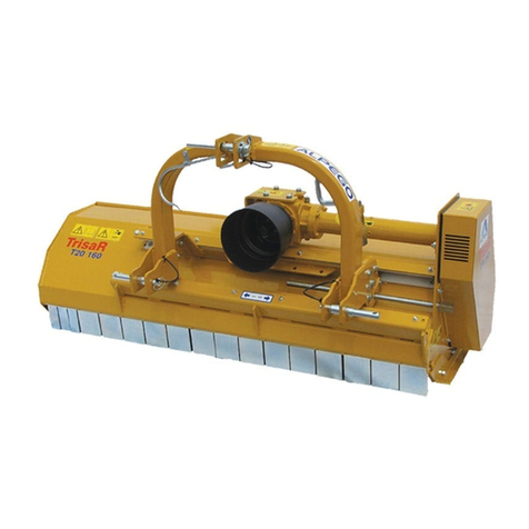
Alpego TT93 User manual

Cod: D14646/5
EN OWNERÊS MANUAL
From Serial No.: 33930
To serial No.: -
Copyright ©2009 della Alpego spa ®
All rights are reserved. Any re production or unauthorized use are specifically forbidden without the written permission of Alpego spa

ALPEGO s.p.a
36053 GAMBELLARA VICENZA ITALIA
VIA TORRI DI CONFINE , 6
TEL. 0444/646100 - FAX 0444/646199
E-mail: info @ alpego.com
Internet: www.alpego.com
CAP. SOCIALE L. 199.000.000
PART. IVA 02009840246
C.C.I.A.A. 199795
REG. SOC. TRIB. VI N° 22374
N. MECC. VI011754
MACCHINE ED ATTREZZATURE PER LA
LAVORAZIONE DEL TERRENO , SINGOLE
E COMBINATE
DISSODATORI, COLTIVATORI
ERPICI ROTANTI , FRESATRICI –
TRIVELLE
I GB D F E
Dichiarazione CE
di conformità’
ai sensi della direttiva
CE 2006/42
La ditta
sottoscritta
EC Certificate
of conformity
conforming to
EEC Directions
2006/42
We
EG Konformitatserklarung
entsprechend der
EG-Richtlinie
2006/42 EWG
Wir
Déclaration de
conformité pour la
CE
conforme à la directive
de la 2006/42 CE
Nous
Declaraciòn CE
de conformidad.
Conforme a la
directiva CE 2006/42
la empresa / el
productor
ALPEGO s.p.a.
VIA TORRI DI CONFINE N°6
36053 GAMBELLARA -(VI)-ITALIA
dichiara sotto
la propria
responsabilità’
che la macchina
modello :
declare in sole
responsability,
that the
product
model :
erklaren in alleineger
Verantwortung,
da das
Produkt
Typ :
déclarons sous
notre seule
responsabilite’
que le produict
modéle :
declara bajo su
propia
responsabilidad que
la màquina
modelo:
Codice / Code: MODELLO MACCHINA
TRINCIA TT TR«SEMIN_AS3__40032_IDRO_PLUS»
N° matricola / serial n°:
È’ Conforme ai
requisiti Essenziali
di Sicurezza e di
Tutela della Salute
di cui alla
Direttiva CE
2006/42
Per l’adeguamento
delle macchine
sono state adottate
le norme:
UNI EN 745
UNI EN 982
UNI EN ISO 4254-1
ISO 11684
to which this
applies, conforms
to the basic safety
and health
requirements of
EC Directions
2006/42
For the adaptation of
it blots some have
been adopted the
norms:
UNI EN 745
UNI EN 982
UNI EN ISO 4254-1
ISO 11684
auf das sich diese
Erklarung bezeith,
den einschlagigen
grundlegenden
Sicherheits und
Gesundheitsan-
forderungen
der EG-Richtlinie
2006/42 EWG
Für die Anpassung von ihr
befleckt einiges sind
angenommen worden den
Normen:
UNI EN 745
UNI EN 982
UNI EN ISO 4254-1
ISO 11684
faisant l’objet de
la déclaration est
conforme aux
prescriptions
fondamentales en
matière de sècuritè et
de santè stipulèes
dans la Directive de la
CE
2006/42
Pour l'adaptation d'elle
en éponge ont été
adoptés les normes :
UNI EN 745
UNI EN 982
UNI EN ISO 4254-1
ISO 11684
està conforme a los
requisitos esenciales de
seguridad y de defeusa
de la salud de la directiva
CE 2006/42
Para la equparaciòn de
las màquinas nan sido
adoptado las normas
UNI EN 745
UNI EN 982
UNI EN ISO 4254-1
ISO 11684
Gambellara: La

Carefully read this manual, before using the machine;
The knowledge of its contents is essential for the
safe use of the implement and it must be kept
throughout the lifespan of the machine.
We thank you for purchasing our machine, you have chosen a high-quality product, guaranteed
by an experience of dozens of years.
Before leaving the factory, each implement is accurately checked to guarantee it is free of any
defect.
If, in spite of this, any problem due to defective materials should arise, please contact
immediately your local dealer.
With the purpose of constantly improving the product and of maintaining it at the highest quality
level, we remain at your complete disposal to give you any information or explanation.
PAY ATTENTION TO THE TRIANGLE, IT MEANS DANGER
THE TERM “MACHINE” REPLACES THE COMMERCIAL DESCRIPTION OF THE ITEM
DESCRIBED IN THIS MANUAL.
The illustrations shown in this Owner’s Manual are meant to be purely
indicative. They may, therefore, present slight differences which are of no
consequence as far as the directions given in the manual are concerned

FOREWORD
The machine is meant for professional operators. Only specialized operators are allowed
to use it.
Use of the machine is forbidden to minors, illiterate people or to people with physical or
mental handicaps.
The use of this machine is forbidden to people who are not in possession of a valid and
adequate driver’s license or are not sufficiently informed or trained. The operator is
responsible for checking the performance of the machine, for the replacement and the
repair of the parts which are subject to wear-and-tear, which could cause damages.
This farm implement can only be operated by means of a universal joint connected with
the PTO of a farm tractor complete with a lifting device and with a universal 3-point hitch.
The regular performance of the implement depends on its correct use and on an adequate
maintenance.
It is, therefore, advisable to strictly follow the advice given herein, in order to avoid any
trouble which may impair the good performance and the lifespan of the implement.
It is also advisable to follow the advice given in this manual, since the Manufacturing
Company will refuse any and all liability for problems arising from negligence or the non-
observance of these rules.
The Manufacturer, however, is absolutely willing to insure an immediate and accurate
technical assistance and to do everything possible to guarantee the best performance and
the maximum yield of the implement.

TABLE OF CONTENTS
1 GENERAL INFORMATION
1.1 Purpose of the Manual
1.2 Documents supplied with the machine
1.3 Warranty
1.4 Identification of the machine
2 TECHNICAL SPECIFICATIONS
2.1 Description of the machine
2.2 Components of the shredder
2.3 Chart of technical data TT93
2.4 Chart of technical data TT97
2.5 Identification of the univarsal joint
3 SAFETY RULES
3.1 Safe Use of the Machine
3.2 Safe Maintenance
3.3 Clothing
3.4 Environment
3.5 Safety Signs
3.6 Sound level
3.7 Warning Signs
4 INSTALLATION
4.1 Lifting
4.2 Machines supplied partly assembled
4.3 Connecting the machine to the tractor and to the 3-point hitch
4.4 Connecting the universal joint
4.5 Checking the lifting capacity and the stability of the tractor
4.6 Assembly of roller scraper
5 DIRECTIONS FOR USE
5.1 Adjustment of the working depth
5.2 Side shift
5.3 Rear Wheels
5.4 Blades
5.5 Directions of Use
5.6 Useful Advice
5.7 Disconnection
5.8 Storage
5.9 Trouble and Trouble Shooting
5.10 Further advice for the Tractor Driver
6 MAINTENANCE
6.1 Check ups and Verifications
6.2 Lateral Transmission
6.3 Replacement of the Blades or Hammers
6.4 Lubrication
6.5 Lubrication Chart
6.6 Chart of the Lubricants to be Used
7 OPTIONS

1 - GENERAL INFORMATION
1.1 PURPOSE OF THE MANUAL
This manual has been written by the Manufacturer of the machine and is an integral part of the documents
accompanying the machine.
The manual defines the purposes for which the machine has been produced, specifying its correct use and the
limits of the same.
The punctual application of the indications contained in the present manual guarantees the safety of the persons
using the machine, the economy of operation and a longer lifespan of the machine.
The present manual has been divided into different paragraphs in order to make the search for the various items and
the consultation of the initial table of contents easier.
The pictures included in this manual are supplied by way of information only. Even if they greatly differ from your
machine, the safety rules and the information are always guaranteed to be applicable and pertinent.
1.2 DOCUMENTS SUPPLIED WITH THE MACHINE
The following documents must be supplied together with the machine
- Owner’s Manual
- Certificate of Compliance to CE Rules
- Owner’s Manual of the Universal Joint
1.3 WARRANTY
At the time of delivery, check whether the machine has been damaged in transit and if all its options are present.
Possible claims must be made in writing to the Dealer within 8 days after receiving the machine.
CONDITIONS OF WARRANTY
The warranty will become immediately void :
-if damage is caused by an incorrect operation
-if the maximum power limit allowed is exceeded (see Chart 2.3)
-in case the instructions given in this manual have not been strictly followed
-if non-original spare parts have been used
-if modifications have been made to the machine without the consent of the Manufacturer.
1.4 IDENTIFICATION OF THE MACHINE
At the 3 points of connection to the tractor is placed the identification plate of the machine bearing the following data:
1. Model of the machine
2. Serial number
3. Maximum weight of the machine
4. Costruction year [es: 1305 = 13 (2013) + 05 (may)]
The specified weight refers to the machine provided with the
accessories.


2 - TECHNICASL SPECIFICATIONS
2.1 DESCRIPTION OF THE MACHINE
Shredders are machines having a rotor which is driven by the tractor PTO through a universal joint and through the gear box
and the lateral belt transmission . They are used for the maintenance of green areas or the direct shredding on the soil where
they chop up organic residues of what is left of the crops (grassy residues). The quality of the shredding depends on the high
speed of the turning rotor, which is opposite to the driving direction of the tractor.
2.2 COMPONENTS OF THE SHREDDER
2
1 - SUPPORT OF THE UNIVERSAL JOINT
2 - UPPER ARM OF 3-POINT HITCH
3 - 3-POINT HITCH
4 - GEAR BOX
5 - IDENTIFICATION TAG
6 - COVER OF LATERAL TRANSMISSION
7 - SIDE SKIDS
8 - PROTECTION PLATES OR CHAINS
9 - LOWER ARMS OF 3-POINT HITCH
10 – TAIL-GATE
11 – REAR ROLLER (not shown in the picture)
12 – SUPPORTING STAND
13 - WHEELS
IFRONT
II REAR
III LEFT-HAND SIDE
IV RIGHT-HAND
SIDE
3
4
5
1
9
7
6
12
I
III
II
IV
13
8

2 - TECHNICAL SPECIFICATIONS
2.3 CHART OF TECHNICAL DATA
MOD. TT93
TECHNICAL DESCRIPTION
Model TT93
- 160 - TT93
- 200 - TT93
- 230 - TT93
- 250 -
Working width 160 200 230 250
Power required (HP) 40/100 50/100 60/100 70/100
Blades (n°) 32 40 48 52
Power of gearbox with free wheel (HP) 100
Transmission belts (n°) 4
Overall width (cm) 200 220 250 270
Overall depth (cm) 135
Overall height (cm) 104
Weight (Kg) 560* 630* 780* 840*
3-Point Hitch (category) II
PTO r.p.m. (r.p.m.)
540
Surface speed (m/s) 62
Rotor r.p.m. (r.p.m.)
1910
Transport position MOUNTED TRANSVERALLY ON LIFTING DEVICE
Primary Transmission UNIVERSAL JOINT OF THE TRACTOR
Secondary Transmission THROUGH SPB SECT. BELT
Adjstment of shredding height MECHANICAL - MANUAL: SKIDS / WHEELS /
ROLLER
Adjustment of side-shift MECHANICAL / HYDRAULIC
Gearbox ratio 1/3
Diameter of rotor pulley (mm) 250
Diameter of gearbox pulley (mm) 212
Rotor diameter (mm) 620
Tube diameter (mm) 193X10
*Weight including universal joint without rear roller
Chart of side shift
TT93-230
TT93-250
TT93-200
TT93-160
1174
1174
794
1554
896
716
516
1096
1226
1226
846
1606
992 992
612
1372
7

2 – TECHNICAL SPECIFICATIONS
2.4 CHART OF TECHNICAL DATA
MOD. TT97
TECHNICAL DESCRIPTION
Model TT97
-280- TT97
-300- TT97
-320-
Working width 280 300 320
Required power (HP) 90/160 90/160 90/160
Blades (No.) 60 64 68
Power of gearbox with free wheel (HP) 160
Transmission belts (No.) 5
Overall width (cm) 300 320 340
Overall depth (cm) 144
Overall height (cm) 105
Weight (Kg) - 1050 -
3-Point hitch (category) II
P.T.O. r.p.m. (RPM)
1000
Rotor surface speed (m/s) 55
Rotor r.p.m. (RPM)
1628
Transport position MOUNTED TRANSVERALLY ON LIFTING DEVICE
OF THE TRACTOR
Primary transmission UNIVERSAL JOINT
Secondary Transmission THROUGH SPB SECT. BELT
Adjustment of shredding height MECHANICAL - MANUAL:
SKIDS/WHEELS/ROLLER
Adjustment of side-shift MECHANICAL/HYDRAULIC
Gear ratio 1/1,92
Diameter of rotor pulley (mm)
212
Diameter of gearbox pulley (mm)
250
Rotor diameter (mm)
645
Tube diameter (mm)
219X12.5
*Weight including universal joint without rear roller

2 - TECHNICAL SPECIFICATIONS
2.5 IDENTIFICATION OF THE UNIVERSAL JOINT
The universal joint should work at a minimum angle of inclination (no more than 10 – 15 degrees) in order to increase
the lifespan of both the universal joint and the machine.
.
It is forbidden to replace it with other universal joints differing from the original.
Carefully read the directions given in the manual attached to the universal joint.
TE CHNICAL DATA OF THE UNIVERSAL JOINTS:
Machine Type Code
TT93-160 A6900-1”3/8 z = 6 1”3/8 z = 6 MO6951
TT93-200 A6900-1”3/8 z = 6 1”3/8 z = 6 MO6951
TT93-230 A6900-1”3/8 z = 6 1”3/8 z = 6 MO6951
TT93-250 A6900-1”3/8 z = 6 1”3/8 z = 6 MO6951
TT97-280 A81100-1”3/4 z = 6 1”3/8 z = 6 MO6953
TT97-300 A81100-1”3/4 z = 6 1”3/8 z = 6 MO6953
TT97-320 A81100-1”3/4 z = 6 1”3/8 z = 6 MO6953

3 SAFETY RULES
3.1 SAFE USE OF THE
MACHINE
Read the owner’s manual carefully before starting-up, before using the machine and before carrying out maintenance
operations on the equipment.
The manufacturer cannot be held responsible for injuries caused to people and animals, or damage caused because
the safety regulations have not been observed by the user.
It is absolutely forbidden to use the machine for purposes differing from the ones indicated in this Manual
Absolutely avoid touching moving parts.
When the machine and its options are transported on public roads, they must be complete with the appropriate
signals and safety guards.
It is forbidden for people to drive the tractor if they do not have an adequate driving licence, if they do not have the
necessary experience, or if they are not in good health.
Carefully check the stickers applied on the machine and follow the directions contained therein. The stickers
concerning safety rules must always be perfectly visible: they must be kept clean and must be replaced if they
become hard to read (they can eventually be obtained from your dealer).
The safety distance from the working machine or from the machine with a turning rotor is 80 meters.
While working never allow people, animals or objects to enter the radius of action of the machine, which may
sling clods, rocks or various residues.
It is absolutely forbidden to enter the area between the tractor and the machine to activate the external
controls of the hydraulic lifting device.
Always remain seated in the tractor driver's seat. Only leave the driver's seat when the tractor power-take-off has
been disengaged and the handbrake has been pulled.
During working breaks switch off the engine, lower the implement to the ground, disengage the tractor power take-off
and pull the tractor handbrake.
Make sure never to operate the machine if any safety guards have been
removed from it.
Do not work in terrains or places which may compromise the stability of the
implement.
Familiarize yourself with the area where you are going to work. Never
operate in areas presenting obstacles such as stones, poles or roots, which
would endanger the integrity of the implement.
When transporting it on public roads always turn on the flashing light.
When circulating on public roads, you must follow the traffic rules of your country. Always remember that road
holding, the ability to brake and changing directions can be influenced by the weight of the machine applied to the
lifting device of the tractor. When taking turns, take into consideration the action of the centrifugal force that shifts the
machine centre of gravity.
50 mt

3 SAFETY RULES
Do not let the implement run when raised (off
the ground). While working do not turn bends
while the machine is set in the ground. Never
work in reverse gear. Always lift it off the ground
when you change directions or drive in reverse
gear.
During transportation, or whenever the machine has to be lifted, the tractor lift should be regulated so that the
machine is kept at a maximum distance of not more than 30 cm. off the ground. Do not circulate on roads if the
machine is dirty with earth, grass or other materials which may soil the roads and/or cause traffic problems . Do not
lower the machine to the ground abruptly , but rather do so slowly .
Unless you follow this rule, strong stressing forces will be exerted on all the components of the machine and they
may compromise its integrity
While driving on the road with the machine lifted off the ground, put the lever controlling the hydraulic lifting
mechanism of the tractor in its locked position.
Never use the machine within closed buildings, if their ventilation system is not adequate.
Before you start the universal joint, make sure that the chosen number of revolutions is correct. Do not mistake 540
rpm for 1000 rpm
Use only the universal joint provided by the Manufacturer, complete with safety devices against overloads.
The safety guards of the universal joint must always be in good working order and
have to be checked at regular intervals and secured by means of chains in order to
prevent them from revolving.
Always disconnect the power takeoff when the universal joint forms an angle
exceeding 15°, see picture.
Always check the integrity of the universal joint, both in its working and in its transport position.
The mounting and/or the removal of the universal joint must always be undertaken with the engine switched off
Always pay a lot of attention to the correct connection and to the safety of the universal joint (and to both the PTO of the machine
and the PTO of the tractor).
Before engaging the PTO make sure there are no people or animals in its area of action and that the chosen rpm are
the correct ones. Never exceed the maximum rpm allowed.
In order to avoid burnings, never touch the gearbox and the components of the hydraulic system (if any) after a
lengthy use of the machine.
The side skids also act as safety guards by preventing an easy access to the rotor. If the machine has no skids, it will
be complete with side safety plates.
The machine is not to be used at night or, at any rate, whenever visibility is insufficient.
Before you start working, familiarize yourself with the control devices and their function.
Mount the machine as prescribed on a tractor having adequate power and configuration by using the appropriate
device (lifting device) complying with the relevant rules
Be extremely careful while hitching and unhitching the implement..
Never leave your driver’s seat while the engine is running..
Before getting off the tractor, lower to the ground the machine hanging on the lifting device, turn off the engine, pull
the hand-brake and remove the ignition key from the dashing board..
The category of the pins for mounting the machine must be the same as the category of the tractor lifting device. During
transportation block with the suitable chains and tie-rods the lower arms of the lifting device.

3 SAFETY RULES
If the tractor being used does not have a sound-proof and pressurized cab, the operator must use individual
protecting gear:
Earmuffs , if the sound exceeds the levels allowed
Dust-protecting mask, if, because of the material being treated or of a very dusty soil, or because the
machine is open, a large amount of dust is raised.
3.2 CARRYING OUT MAINTENANCE
SAFELY
DO NOT allow unauthorised people to carry out maintenance operations or to tamper with the machine in any way.
The use of the machine without protection plates or chains is strictly forbidden.
Plates Chains
Maintenance and repairs must be carried out in a suitable and well equipped workshop.
Before undertaking any maintenance operation disconnect the hydraulic hoses from the tractor oil plugs.
Always use original options and spare parts as instructed by the Manufacturer. If you fail to do this, the guarantee will
be rendered null and void, and you could risk operational irregularities that could prejudice the safety of the machine.
Make sure that the oils used have the recommended characteristics.
Before carrying out any operation on the machine, disengage the tractor power takeoff, pull the handbrake, remove
the ignition key and make sure that other people do not get into the tractor.
Before cleaning and lubricating the universal joint, stop the PTO, turn off the engine, pull the hand-brake and remove
the ignition key.
Before replacing the gears in the gearbox stop the PTO, pull the hand-brake and remove the ignition key. Then put
the lid of the gearbox back in place, before you start the machine again.
When the universal joint is not being used, prop it on the appropriate supporting hook (see picture)
Periodically check the tightness and the hold of all the nuts and bolts and tighten them, if necessary.
When maintaining and replacing the blades while the machine is lifted off the ground, prop up the machine on
suitable supporting stands.
Before working on the cutting tools, stop the PTO, turn off the engine, pull the hand-brake and make sure that the
cutting tools are completely still.
The spare parts must fulfill the requirements set forth by the Manufacturer. Only use original spare parts.
The Owner’s Manual must be kept for the entire lifespan of the machine.
Supportino hook for
universal joint

3 SAFETU RULES
3.3 CLOTHING
Always put on clothes protecting the body with no hanging parts that could get entangled in moving components.
Remove watches, rings, necklaces, etc. that could cause injury in dangerous situations. Tie up long hair into a
ponytail.
When required by the Law, the machine driver may have to wear suitable
safety equipment (glasses, gloves, mask, helmet, shoes, etc.). Check and
follow the safety rules in your country.
3.4 ENVIRONMENT
Always comply with the Laws of your country concerning the use and disposal of the products used for the lubrication,
the maintenance and the clearing of the machine; carefully follow the directions given on the packaging of the
products.
Comply also with the current rules when scrapping the implement.
3.5 SAFETY SIGNALS
A good number of labels on the machine point out the sources of danger. Observe them carefully and follow the
instructions for safe machine use. These stickers should be kept clean and legible. If damaged, they must be
replaced.
figura codice indicazioni
D02612
You MUST read the user and maintenance
manual and the safety instructions before using
the equipment. The manual and the instructions
must be followed during use.
D02627 Indicates the hooking point for machine
transportation
D02613 Indicates the danger of shearing while the
machine is working
D02618 Indicates the danger of flying rocks while the
machine is working.
D02619 Warns against the danger caused by the turning
rotor and recommends keeping a safe distance
D02608 Indicates the danger of entanglement while
working on the universal joint shaft. Do not
approach the shaft while it is rotating.
D02615 Indicates the need to switch off the tractor and
remove the ignition key during maintenance
operations
D02609 Indicates that it is forbidden to climb on top of the
machine while it is working.

3 SAFETU RULES
D02614 Indicates the danger of being crushed by turning
belts and pulleys
D02624 Indicates the danger caused by pressurised oil if
the hydraulic pipes break. Consult the instruction
manual before repairing the hydraulic system.
D08155 Indicates the danger caused by excessive noise
during while working
3.6 SOUND LEVEL
If the tractor has a cab, the sound level depends on the type of insulation of the cab.
If the tractor has no cab or if its windows are open, the sound level of the working machine, at a distance of
200 mm. from the rear window exceeds 85 dBa. Therefore, we recommend the use of soundproof earmuffs as
prescribed by the laws of different Countries.
3.7 Information signs
1. Hooking point for lifting (Max. lifting capacity is given.)
2. Oil-filling cap.
3. Oil discharge cap.
4. Oil-level check-up cap.
5. Greasing point.
6. R.p.m. of the PTO.
If the protection guards have been supplied separately because of transport reasons, mount them
before you start the machine for the first time.

4 ASSEMBLY
4.1 LIFTING THE MACHINE
The lifting and transport operations must be performed with means suited to the weight of the machine.
Hook the machine as shown in the picture and then transport it. During the latter operation the machine should not be
lifted more than 200 mm off the ground.
4.2 MACHINES SUPPLIED PARTLY DISASSEMBLED
Sometimes machines may be delivered with some components or options not assembled because of dimension
reasons (They are, however, always included in the same package)
Undertake the assembly of these parts very carefully, also taking into consideration the charts in the spare part
catalogue and, more specifically, comply with the values given concerning the torque wrench settings of the bolts
supplied with the parts.
4.3 CONNECTING THE MACHINE TO THE TRACTOR AND TO THE 3-POINT HITCH
The mounting of the machine on the tractor is a very dangerous operation. Pay the utmost attention
and follow all directions closely while performing the entire operation. The Manufacturer will not be
held responsible for breakings or damages to property or people caused by the non-observance of
the directions contained herein.
The correct position of the tractor and the machine is determined in that the tractor should be driven to such a
distance from the machine, that the universal joint remains extended by 10-15 cm. from its maximum retracted
position.
1. Bring the lower arms of the lifting device of the tractor to rest inside the plates (A-B-C Pict..), insert the pin
into the corresponding holes and lock with the spring pins.
2. Block the lower arms of the lifting device with the proper chains and parallel tie rods of the tractor. This
procedure is to be carried out to prevent any shifting of the machine in the transversal direction
3. Connect the upper arm (C Pict..) and adjust correctly through the tie rod, making sure that the top of the
machine is parallel to the ground.
This adjustment is very important in order to obtain a parallel setting between the axis of the shaft of the PTO
of the machine and the axis of the shaft of the PTO of the tractor. Working with the machine thus adjusted
implies keeping the vibrations of the PTO at a bare minimum, which in turn helps to lengthen the lifespan of
the PTO, of the universal joint and of the machine itself.
4. Connect the universal joint and make sure it is perfectly latched on the PTO. Make sure that the protecting
guard turns freely, then secure it with the proper chain. Remove the support from the universal joint.
5. Move the supporting stands from the parking to the working position

4 ASSEMBLY
4.4 OF THE UNIVERSAL JOINT
The angle of inclination of the working universal joint must be as small as possible (no more than 10 ÷ 15 degrees).
This will improve the lifespan of both the universal joint and of the machine (see picture).
Since the universal joint is an organ which rotates at a rather high speed, during its calibration it undergoes a
balancing adjustment: any modification following this operation may impair the performance of the machine, as well
as the performance of the universal joint itself.
When the universal joint is in its most stretched position, whatever the working conditions, the telescopic tubes must
overlap by at least 1/3 of their length..
When it is in its most retracted position the minimum play should amount to 4 cm..
If this is not possible, please call the Technical Dept. of the Manufacturing Co..
Before you begin working, make sure that the proper chains are present on the safety guards, in order to prevent the
guards from rotating together with the universal joint and make also sure that these guards are in perfect working
order.
Carefully read the Owner’s Manual supplied with the universal joint supplied by the Manufacturer of
the same.
If the universal joint is worn out or broken, replace it with one bearing the sign .
The Manufacturer of the universal joint warns against any modification of the universal joint.
It is, therefore, forbidden to perform any modification or variation of the universal joint.
4.5 CHECKING THE LIFTING CAPACITY AND THE STABILITY OF THE TRACTOR
When an implement is mounted on a tractor, it becomes an integral part of the same, as far as
travelling on public roads is concerned, and it can alter its stability and cause some driving and
working difficulties.
When you mount a machine on the tractor, you will change the weight
distribution over the axes. It is, therefore, advisable to add suitable
ballast to the front of the tractor in order to have a good weight
distribution over the axes.
Calculate the ballast to be used with the following formula:
M x s < 0,2 T x i + Z ( d + i )
( M x s ) – ( 0,2 T x i )
Z > -----------------------------------------------------------
( d + i )
where:
i = tractor wheel inter-axis (m)
d = distance between the front axis and the front ballast (m)
s= projection of the piece of equipment from the rear axis (m)
T = tractor mass (kg)
Z= ballast + hopper with seeds mass (Kg)
M= equipment mass (Kg)

4 ASSEMBLY
At least 20% of the total tractor/implement mass
should bear on the front bridge of the tractor. It
should be remembered, however, that stability can
be improved with the right choice of
tractor/implement coupling and with the application
of ballast at the front, within the limits and methods
indicated by the tractor manufacturer. Moreover,
when the tractor is stopped, the machine should be
lowered onto the ground. This also improves
stability.
Tractor wheel inter-axis i =……………… m
Distance between the front
axis and the front ballast d =………………m
Projection of the piece of
equipment from the rear axis s =………….. ….m
Tractor mass T =………………Kg
Ballast mass Z =………………Kg
Implement mass M =……………...Kg
4.6 ASSEMBLY OF ROLLER SCRAPER
The kit for scraping the mud from the rear roller is meant to keep the rear roller clean whenever it is working under
particularly severe conditions or in hostile environments. For this reason it is supplied standard but not assembled on
the shredder. The operator will decide whether to mount it on the machine depending on the working conditions.
The assembly is done inside the roller-supporting flanges using the same holes to secure it. It is necessary to use the
bolts supplied in the kit.
Secure both supports Insert the special bolt Adjust the height of the L-bar
When adjusting the L-bar make sure the roller can turn without any hindrance.
Any kind of contact can irreparably ruin or damage the machine

5 DIRECTIONS FOR USE
5.1 ADJUSTMENT OF THE WORKING DEPTH
Lift the implement off the ground and adjust
the working height.
Adjust the position of the machine with the lifting
device, making sure that the machine is horizontal or
only slightly higher at the front, in order to make the
intake of the material to be shredded easier.
In order for the machine to work properly it is necessary for
the blades to work at a minimum height of 2,50 cm. from the
ground. It is possible to adjust the shredding height by
acting on the skids, on the rear roller or on the tie-rod of the
upper arm of the tractor. The higher the blades are from the
ground, the smaller is their wear and the lower the power
absorbed.
a) Adjustment of the skids:
unscrew the bolts holding the skids at the sides of the
shredder, position the skids at the desired height and
tighten the bolts again;
b) Adjustment of the rear roller
unscrew the bolts holding the rear roller, position the
skids at the desired height and tighten the bolts again;
;
c) Adjustment of the tie-rod of the upper arm:
Lengthen or shorten the tie-rod of the upper arm of the
tractor in order to adjust the working height and place the
machine parallel to the ground
Adjustment of the
skids
Adjustment of the rear
rolller
Up
per arm

5 – DIRECTIONS FOR USE
5.2 SIDE SHIFT
The shredder may be complete with a manual or hydraulic side-shift of the frame of the 3-point hitch. This side-shift
is used when working close to ditches or in crops requiring the machine to be displaced laterally.
* MECHANICAL SIDE-SHIFT (with a telescopic tube)
The mechanical (or manual) side shift is to be set when the machine is standing still and not mounted on
the tractor
In order to obtain the side-shift proceed as follows:
-Remove the retaining pin from the bar (a)
-Shift the frame of the 3-point hitch (b) to the position suited to the job one needs to do
-Insert the retaining pin into the nearest hole
-Hitch the machine to the tractor
* HYDRAULIC SIDE-SHIFT
It can comfortably be activated with the machine mounted on the tractor: Plug the standard hydraulic hoses
into the corresponding plugs of the hydraulic circuit of the tractor, while keeping the machine a few
centimeters off the ground. Activate the controls from the driver’s seat and determine the extent of the side
shift of the implement (see picture).
Take into account the fact that the shifting of the implement entails a variation of the working
inclination of the universal joint. Make sure that this remains within the safety limits.
This manual suits for next models
1
Table of contents
Other Alpego Paper Shredder manuals