1.1 Safety and Warning
Introducon01
INTRODUCTION INTRODUCTION
1)Keep explosive or flammable materials, chemicals, vapors, and other hazardous
objects away from the charger.
2)Keep the charging socket clean and dry. If it is dirty, please wipe it with a clean and
dry cloth. Touching the socket core when the power is on is strictly forbid-den.
3)Do not use the charger if the device has defects, cracks, abrasions, bare leakage, or
any similar issues. Please contact the working staff if any of these condions occur.
4)Do not aempt to disassemble, repair, or modify the charger. If necessary, please
contact the working staff. The improper operaon could result in device damage, electric
leakage, etc.
5)If any abnormal condion happens, please press the emergency stop buon
immediately and cut off all input and output power supply.
6)Please charge cauously in rainy or lightning weather.
7)Keep the charger away from children to avoid injury.
8)Driving an EV during charging is strictly forbidden. Charge the EV only when it is
staonary. Charge hybrid electric vehicles only when the engine is switched off.
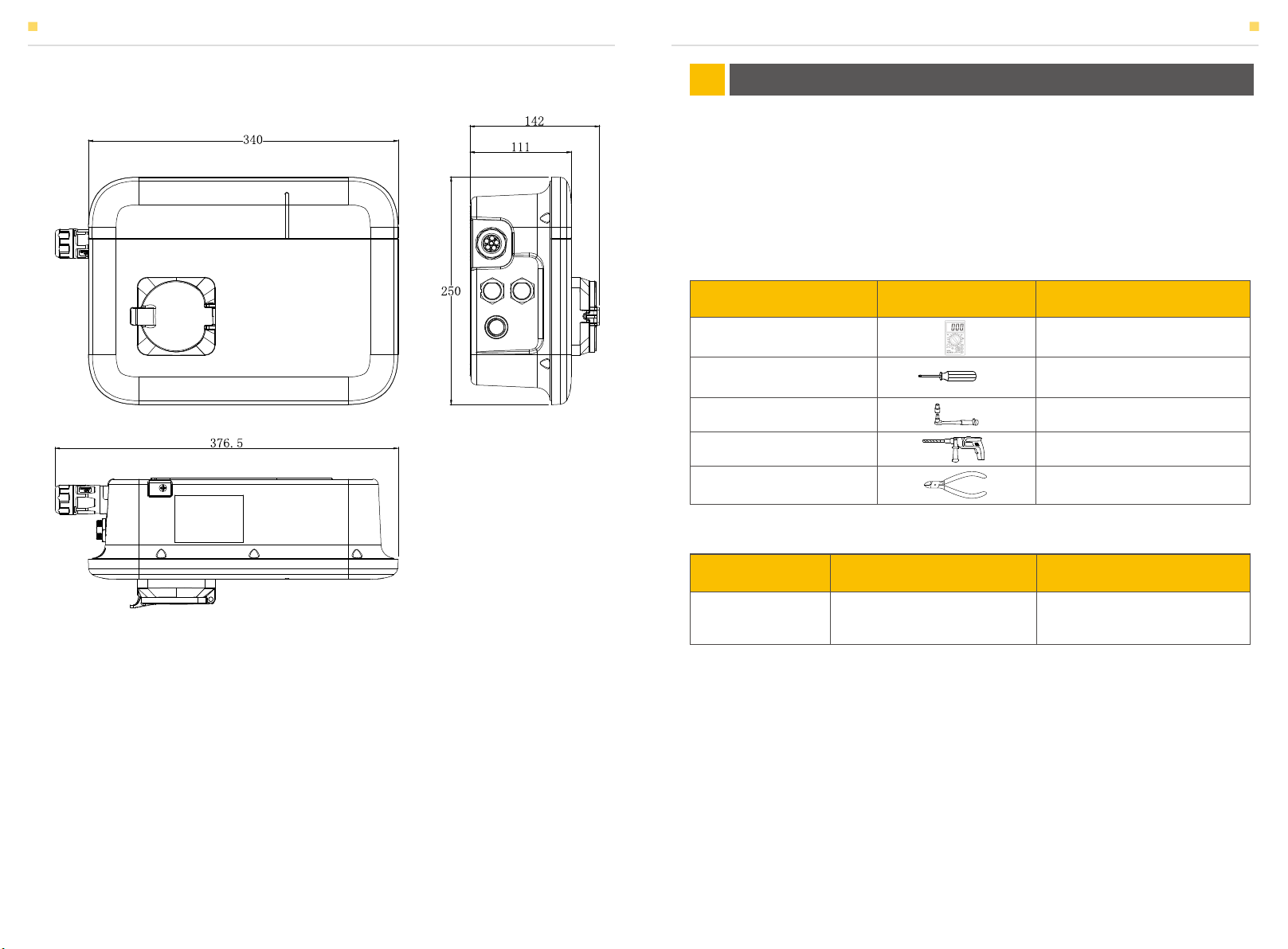
1.2 Scope of Delivery
Check the scope of delivery and inspect components to ensure they are present and
undamaged. Contact your distributor if the packed components are incomplete or
1.3 Liability Limitaon
AlphaESS will not assume any direct or indirect liability for any product damage or
property loss caused by the following condions:
• Product modificaon, design changes, or parts replacement without AlphaESS’s
authorizaon;
• Changes or aempted repairs, and erasing of series number or seals by unauthorized
technicians;
• The product wiring and installaon are not in compliance with standards and
regulaons;
• Failure to comply with the local safety regulaons;
• Transport damage (including painng scratch caused by rubbing inside packaging during
shipping). A claim should be made directly to the shipping or insurance company as
soon
as the container/packaging is unloaded and such damage is idenfied;
• Failure to follow any/all of the user manual, installaon guide, and maintenance
regulaons;
• Improper use or misuse of the device;
• Insufficient venlaon of the device;
• The product maintenance procedures have not been in compliance with an acceptable
standard;
• Force majeure (violent or stormy weather, lightning, overvoltage, fire, etc.);
• Damages caused by any external factors.
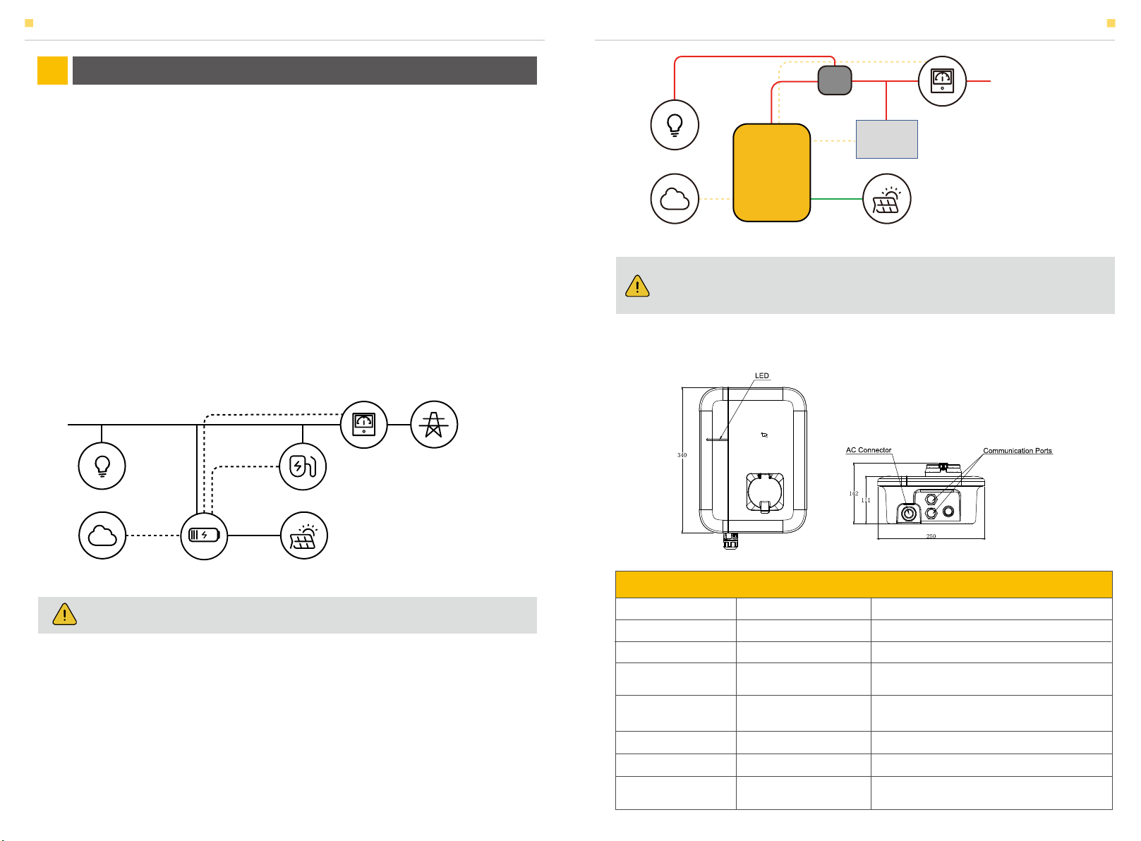
The input and output voltages of this device are dangerously high and
can pose a threat to human life. Please strictly observe all warn-ings and
operang instrucons on the device and in the manual. Un-authorized
and non-professional service personnel should not re-move the cover of
this device.
SMILE-G3-EVCT11
Warning
01 02
EV Charger
(x1)
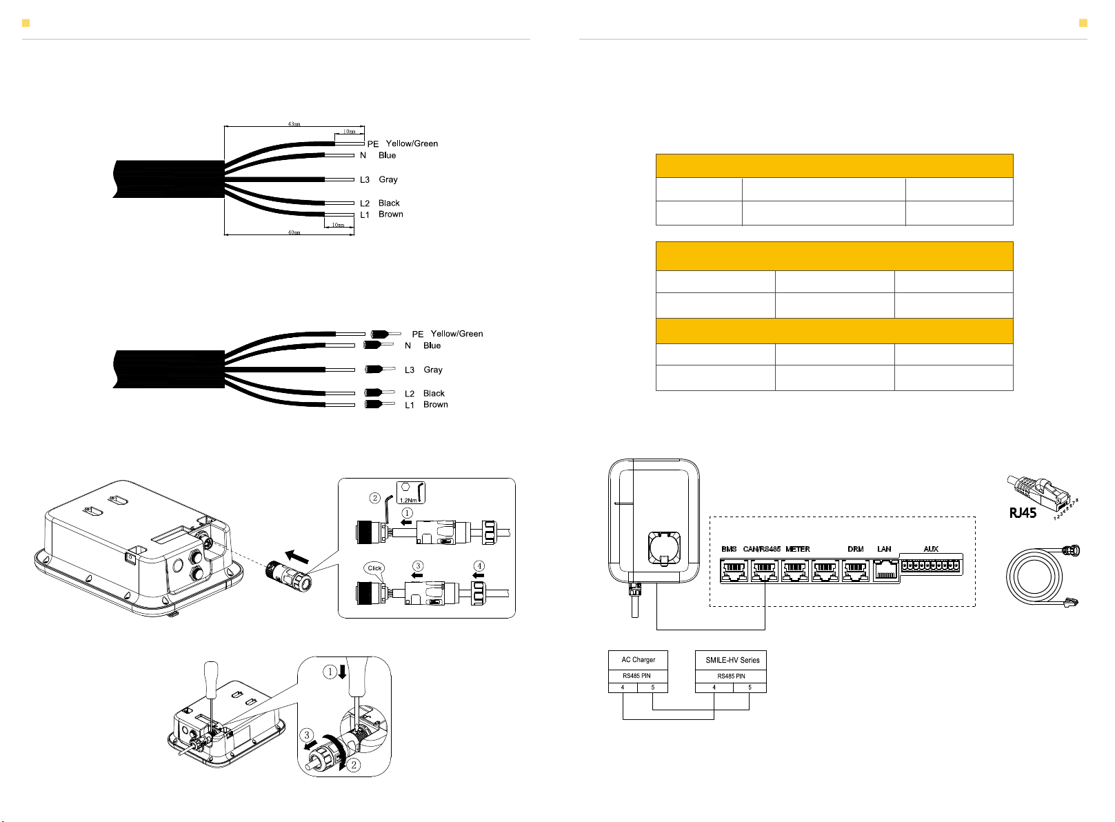
Terminal block
(x5)
AC Connector
(x1)
Installaon, operaon
& Maintenance Manual
(x1)
Terminal Resistor
(x2)
RFID Card
(x2)
M6*40 Screw
(x4)
Wall bracket
(x1)
Wrench
(x1)