8 of 110
1.1 Introduction
This handbook contains 8 sections and gives the operator a general overall description of the
Alpha 800 UAV.
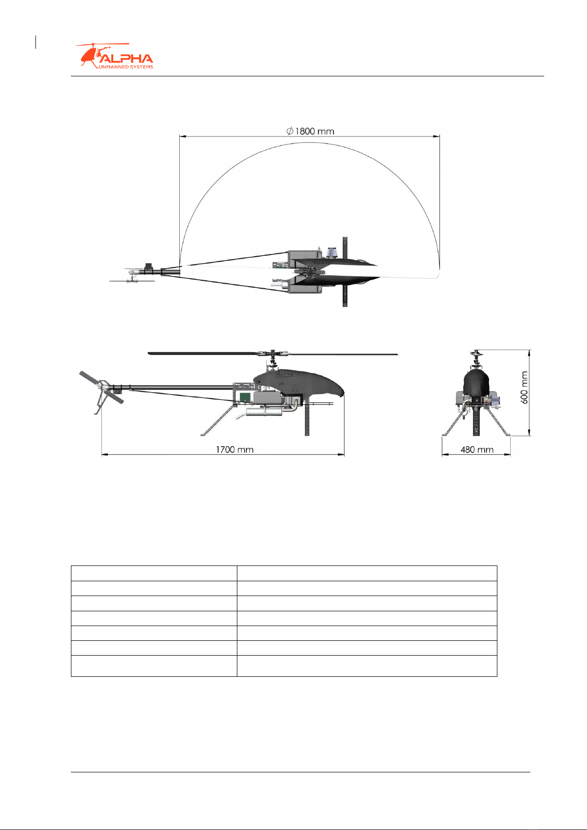
1.2 The ALPHA 800 UAV
The Alpha 800 is a rotary wing unmanned aircraft that operates as a helicopter with the
possibility of vertical take-off and landing, hovering and navigating in automatic flight
according to a previously-loaded flight plan. The operation is monitored by a Ground Control
Station (GCS) and communications between the UAV and the GCS are in real time, allowing
the ground operator to observe the images captured by the video camera installed on-board
or the data from any other client-specified payload, as well as to have full manual UAV control
by means of a joystick.
The ALPHA 800 can be used for a wide range of applications where an onboard operator’s
presence is not necessary. Avoiding risk to humans, unmanned aerial vehicles can be used for
military or civilian applications, such as aerial surveillance and reconnaissance, fire detection,
monitoring of law enforcement, etc.
The ALPHA 800 is a tactical, automatic VTOL UAV. It is suitable for day or night, non-military
or “Intelligence, Surveillance, Target Acquisition and Reconnaissance” (ISTAR) missions. The
ALPHA 800 can provide, depending on the configuration, from 2 to 3 hour endurance missions
with multiple payload capabilities.
Avoiding the need for highly qualified personnel, ALPHA 800 can complete its entire mission
automatically, from take-off to landing by means of a compact, redundant flight control
system.