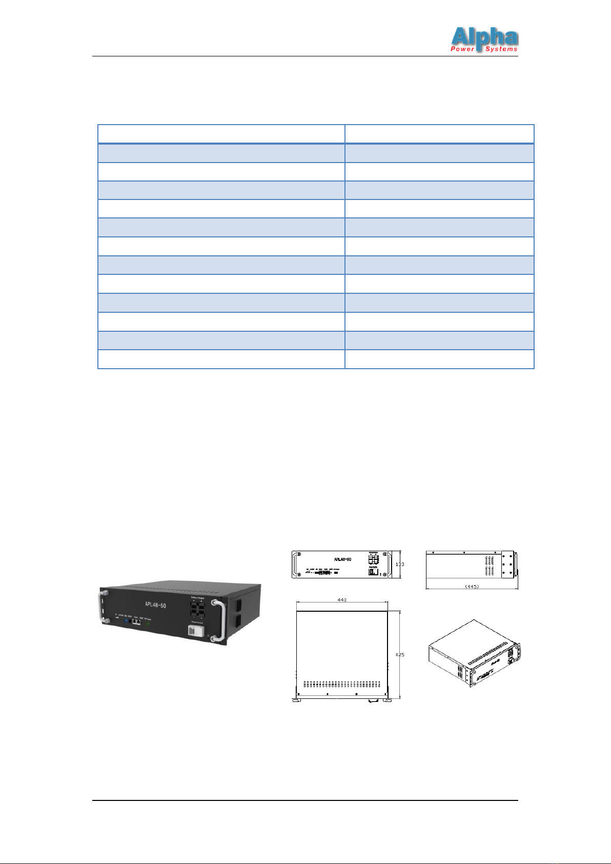
APL48-50LFP liFePO4 Battery Operation Manual
2.3–Battery Management System (BMS)
Integrated Smart BMS technology is adopted for battery modules of APL-LFP to assure smart
automatic management for batteries. Features of BMS are shown as below:
Overcharge Protection
When the voltage of any cell is greater than the overcharge detection voltage and the duration
exceeds the delay time of the overcharge detection, the protective plate judges that the over-
voltage state occurs and the charging MOSFET is closed, charging to the battery pack is
prohibited.
When the voltage of the highest cell after overvoltage occurs restores to the overcharge recovery
voltage or below, the protection plate judges that the over-charge state has been relieved. At the
same time, the charging MOSFET is turned on, the charger can charge to the battery pack, and
the green RUN light on the protection plate shines during charging.
The battery pack can still discharge to the load when the overvoltage state occurs.
Over-discharge Protection
When the voltage of any cell is less than the over-discharge detection voltage and the duration
exceeds the delay time of the discharge detection, the protective plate judges that the over-
discharge state occurs. The green RUN lamp and red ALM lamp are both extinguished, discharge
MOSFET is closed, and the battery pack is prohibited to discharge to the load.
When discharge under-voltage occurs, the protection plate goes to sleep, and the charging input
can be waked up by adding a charger.
Overcurrent/short circuit protection and recovery
When the discharge current exceeds the short-circuit protection current and the duration
exceeds the delay time of the short-circuit detection, the red ALM lamp is glitter, and the
protection plate enters the over-current protection/short-circuit protection state, under which
charge-discharge is prohibited.
After the protection plate enters the overcurrent/short circuit state, it will lock the state until the
charging input can be activated by adding a charger.
Heat Management
With the function of cell and environment temperature detection, when the temperature is too
high or too low the product will start up alarming and protection function. The temperature
sampling accuracy is less than ± 2°C within the operating temperature range. Four battery
temperature detection points and one ambient temperature detection point (maximum 16
battery temperature detection points) are supported by default.