manuals.online logo
Brands
  1. Home
  2. •
  3. Brands
  4. •
  5. Alpha
  6. •
  7. Marine Radio
  8. •
  9. Alpha XP-EDH3 User manual

Alpha XP-EDH3 User manual

Alpha Technologies
Alpha XP-EDH3 Transponder
Field Installation Instructions
Effective: February 2009
Before eld installation, the transponder's MAC address should be loaded into the CMTS, and DOCSIS conguration le
options should be set.
Alpha XM, XM2 and AM Models
See Subsequent Sections for power supply-specic setup instructions
Power Supply Communications Card Settings
XM - USM
P1 = 2 & 3
P2, P4, P5, P6 = Closed
P3 = Open
P7 = 5V
P8, P9, P13 = 1 & 2
P14 = N/A
SW4 = 0
Output Current switch settings are determined by the output current capability of the power supply and should be
setup accordingly. See your power supply user manual for setting details.
USM: N/A•
USM2: SW1-3 = Output #1, SW1-4 = Output #2•
USM2.5: SW1-3 = Output Current Scaling, 15A or 22A•
RPM : No switch setting required•
XM2 - USM2
SW1-1, 2, 6, 8 = On
SW2-1, 3, 4 = On
JP1 = C & 1
JP2 = 1 & 2
XM2 - USM2.5
SW1-1, 2, 6 = On
Overview to the eld installation instructions
CAUTION!
Use a surge protector in the cabinet when the transformer is used to measure line voltage.
Do not place the transponder on top of the power supply or batteries.
Make all battery harness connections and connect the interface cable to the power supply before
connecting the cables to the transponder.
745-419-C3-001 Rev. A (02/2009)
2
The XP-EDH3 transponder provides the ability to manage network power through an existing cable modem
infrastructure, for a variety of power supplies as shown in this document.
These instructions provide information important to the successful installation, connection and operational verication of
the Alpha XP-EDH3 transponder in a variety of systems.
Save these instructons for future reference.
Alpha AM power supplies with RPM interface cards marked 700-019-28, 700-019-31 and 700-019-40 are
compatible with the DOCSIS HMS Analog Transponder.
NOTE:
NOTE:
1. Switch Battery Breaker OFF prior to removing the Inverter Module for USM Card installation and conguration.
A chipset upgrade may be required; contact Alpha for more information.
Set the jumpers and calibrate the USM card before making connections and applying the load.
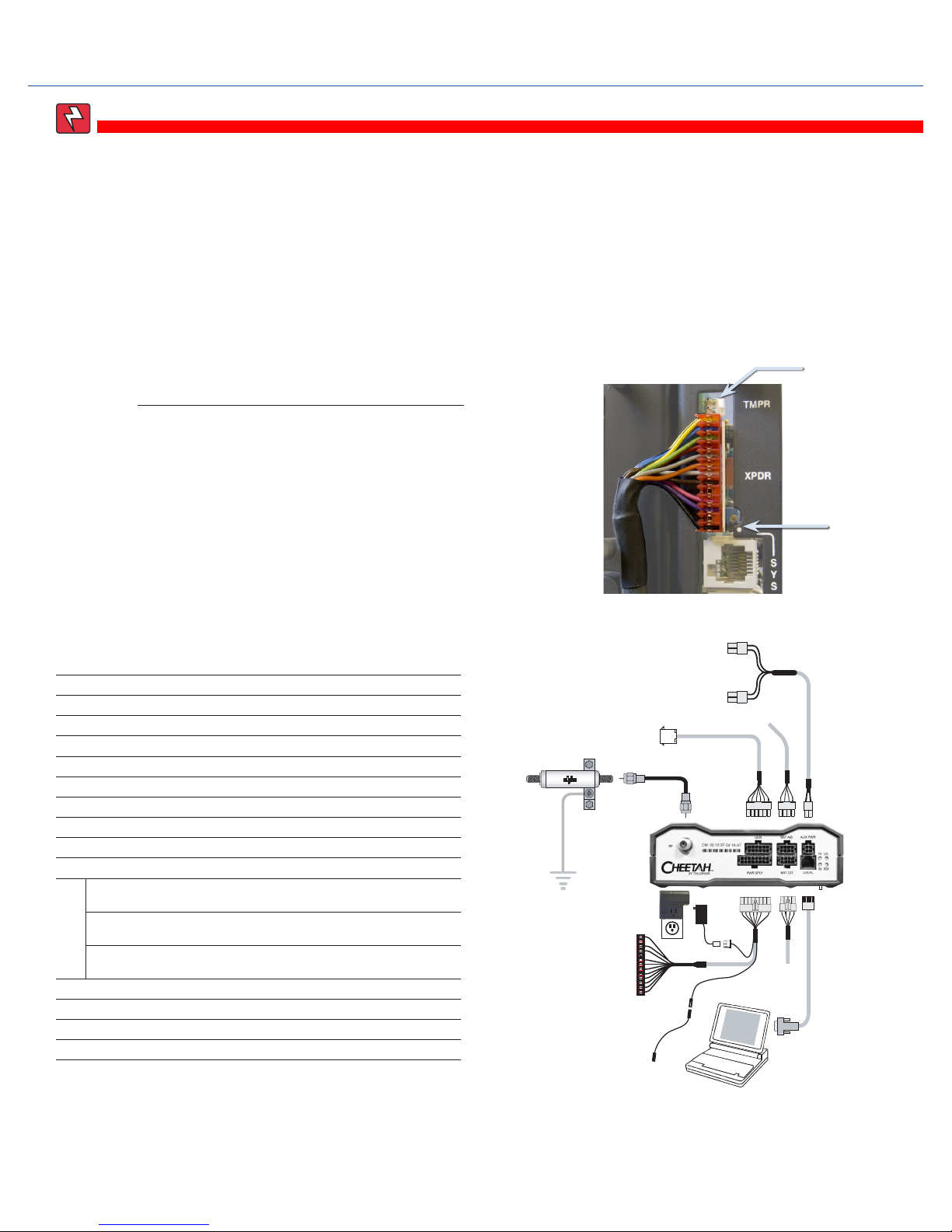
When connecting to an AM Series power supply, plug the 13-pin
connector so the black wire is in pin1 and two open pins are left
at the left for tamper switch connection (as viewed from the front
of the unit)..
AM SERIES POWER SUPPLY CONNECTION
Connection Instructions for the Alpha AM, XM Series Power Supply
Legend
1 Generator Interface (as needed) Alpha p/n 874-975-20
2, 5 Battery Sense Wire Kit for: 36V single string, 6', Alpha p/n 874-842-21
36V single string, 9', Alpha p/n 874-842-27
36V dual string, 6', Alpha p/n 874-842-20
36V dual string, 9', Alpha p/n 874-842-28
48V single string, 6', Alpha p/n 875-841-21
48V single string, 9' Alpha p/n 875-841-25
48V dual string, 6', Alpha p/n 875-841-20
48V dual string, 9', Alpha p/n 875-841-24
3 Ignition Battery/Aux Power Cable Alpha p/n 874-976-20
4
XM Series 2 Power Supply
Interface Cable
Alpha p/n 875-335-20 (USM2/2.5)
XM Series Power Supply
Interface Cable
Alpha p/n: 875-335-21 (USM)
AM Series Power Supply
Interface Cable
Alpha p/n: 875-335-21 (RPM)
6 Craft Port Cable (optional) Alpha p/n 875-349-10
7 RTS Cable (optional) Alpha p/n 745-178-21
8 Vin Sense (optional) Alpha p/n 875-493-21
9 Surge Protector Ground Block Alpha p/n 162-028-10
10 Plug-in Lightning Arrestor w/pass thru
(130V) L-G, L-N, N-G
Alpha p/n 162-046-10
WARNING!
When installing Battery Sense Cable Kit (BSC) or AlphaGuard sense cable, do not connect the black
(negative) wire of the BSC to the negative post on Battery 1.
2. It is advisable to install the Battery or Aux pwr cables (providing power to the External DOCSIS unit) and waiting until
the RDY LED is ashing normally before installing the power supply interface kit. This will reduce the chances of the
power supply transferring to inverter due to a low signal reference on the test control pin.
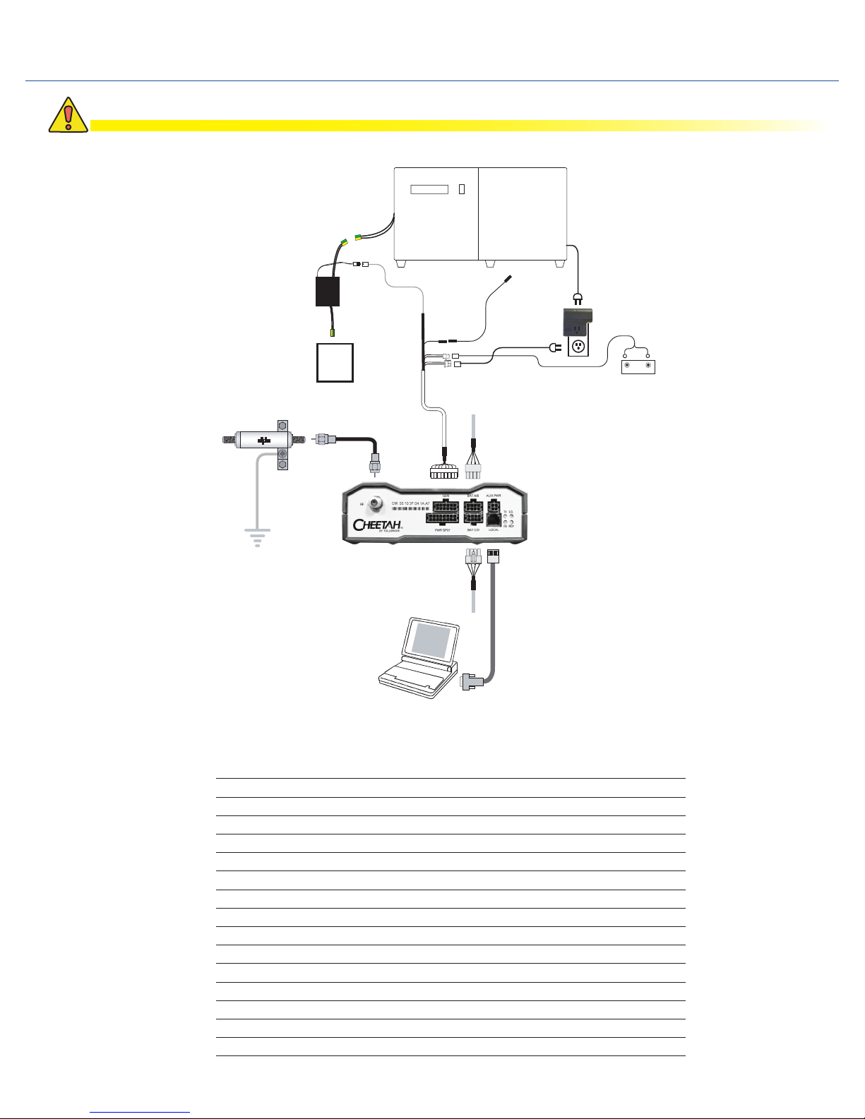
When connecting to an XM Series power supply, plug the 13-pin
connector so the black wire is in pin1 and two open pins are left at
the bottom for tamper switch connection (as viewed from the front
of the unit).
XM SERIES POWER SUPPLY CONNECTION
745-419-C3-001 Rev. A (02/2009) 3
1
2
3
456
7
8
9
Pin 1
Tamper switch
connection point
Connections between transponder, power supply and laptop
NOTE:
Pin 1
Tamper switch
connection point
10
745-419-C3-001 Rev. A (02/2009)
4
The XM2 batteries are isolated from chassis ground by design. Any voltage potential difference between battery (-)
and chassis ground must be eliminated before installing the transponder to avoid potential transponder damage. To
accomplish this, attach a ground jumper between battery (-) and chassis ground before installing the transponder. Once
the transponder is installed the jumper may be removed if desired.
WARNING!
Connection Instructions for the Alpha XM Series 2 Power Supply
Switch Battery Breaker OFF prior to removing the Inverter Module for USM2/USM2.5 Card installation and conguration.
When connecting to an XM Series 2 power supply, plug the 13-pin
connector so the black wire is in pin1 and two open pins are left at
the top for tamper switch connection.
XM SerieS 2 Power SuPPly ConneCtion note:
Connections between transponder, power supply and laptop
1
2
3
45
6
7
8
9
Pin 1
Tamper switch
connector
Legend
1 Generator Interface (as needed) Alpha p/n 874-975-20
2, 5 Battery Sense Wire Kit for: 36V single string, 6', Alpha p/n 874-842-21
36V single string, 9', Alpha p/n 874-842-27
36V dual string, 6', Alpha p/n 874-842-20
36V dual string, 9', Alpha p/n 874-842-28
48V single string, 6', Alpha p/n 875-841-21
48V single string, 9' Alpha p/n 875-841-25
48V dual string, 6', Alpha p/n 875-841-20
48V dual string, 9', Alpha p/n 875-841-24
3 Ignition Battery/Aux Power Cable Alpha p/n 874-976-20
4
XM Series 2 Power Supply
Interface Cable
Alpha p/n 875-335-20 (USM2/2.5)
XM Series Power Supply
Interface Cable
Alpha p/n: 875-335-21 (USM)
AM Series Power Supply
Interface Cable
Alpha p/n: 875-335-21 (RPM)
6 Craft Port Cable (optional) Alpha p/n 875-349-10
7 RTS Cable (optional) Alpha p/n 745-178-21
8 Vin Sense (optional) Alpha p/n 875-493-21
9 Surge Protector Ground Block Alpha p/n 162-028-10
10 Plug-in Lightning Arrestor w/pass thru
(130V) L-G, L-N, N-G
Alpha p/n 162-046-10
10
Installation of the Vout and Iout sense harness requires powering down the power supply. Use an alternate
source of power during this procedure.
CAUTION!
745-419-C3-001 Rev. A (02/2009) 5
Input and Output Connections, ZTT and ZTT+ Models
Connections between transponder, power supply and laptop
Legend
1Power Supply Interface Alpha P/N: 875-335-22 (ZTT and ZTT+ Post 1998)
Alpha P/N: 875-335-23 (ZTT+ Pre 1998)
2 Battery Sense Wire Kit for: 36V single string, 6', Alpha p/n 874-842-21
36V single string, 9', Alpha p/n 874-842-27
36V dual string, 6', Alpha p/n 874-842-20
36V dual string, 9', Alpha p/n 874-842-28
48V single string, 6', Alpha p/n 875-841-21
48V single string, 9' Alpha p/n 875-841-25
48V dual string, 6', Alpha p/n 875-841-20
48V dual string, 9', Alpha p/n 875-841-24
3 Craft Port Cable (optional) Alpha p/n 875-349-10
4 RTS Cable (optional) Alpha p/n 745-178-21
5 Vin Sense (optional) Alpha p/n 875-493-21
6 Surge Protector Ground Block Alpha p/n 162-028-10
7 Vout Iout Sense Harness Alpha p/n 875-456-10
8 Tamper Wire Kit Alpha p/n 875-493-21
9Plug-in Lightning Arrestor w/pass thru
(130V) L-G, L-N, N-G
Alpha p/n 162-046-10
SPI
ZTT/+
1
2 3
4
5
6
7
8
2
9

Popular Marine Radio manuals by other brands

Garmin GTX 45R installation manual

Garmin

Garmin GTX 45R installation manual

Garmin GTX 33 installation manual

Garmin

Garmin GTX 33 installation manual

Thrane&Thrane TT-6222A VHF DSC user manual

Thrane&Thrane

Thrane&Thrane TT-6222A VHF DSC user manual

Vesper Cortex HV1 installation guide

Vesper

Vesper Cortex HV1 installation guide

Thrane&Thrane Sailor RT5022 VHF DSC manual

Thrane&Thrane

Thrane&Thrane Sailor RT5022 VHF DSC manual

Saab R5 SUPREME AIS Operation & installation manual

Saab

Saab R5 SUPREME AIS Operation & installation manual

West Marine VHF580 owner's manual

West Marine

West Marine VHF580 owner's manual

Garmin VHF 315 Series installation instructions

Garmin

Garmin VHF 315 Series installation instructions

Barco MDSC-2226 user guide

Barco

Barco MDSC-2226 user guide

West Marine VHF490 owner's manual

West Marine

West Marine VHF490 owner's manual

GME GX800 instruction manual

GME

GME GX800 instruction manual

Garmin VHF100 - 25W VHF RADIO Declaration of conformity

Garmin

Garmin VHF100 - 25W VHF RADIO Declaration of conformity

Uniden UM425 VHF DSC owner's manual

Uniden

Uniden UM425 VHF DSC owner's manual

Kongsberg cNODE MiniS LF instruction manual

Kongsberg

Kongsberg cNODE MiniS LF instruction manual

Trig Avionics TT26 installation manual

Trig Avionics

Trig Avionics TT26 installation manual

West Marine VHF500 owner's manual

West Marine

West Marine VHF500 owner's manual

Siemens SIMATIC RTLS4060T manual

Siemens

Siemens SIMATIC RTLS4060T manual

Cobra Marine MARINE MR HH330 FLOAT owner's manual

Cobra Marine

Cobra Marine MARINE MR HH330 FLOAT owner's manual

manuals.online logo
manuals.online logoBrands
  • About & Mission
  • Contact us
  • Privacy Policy
  • Terms and Conditions

Copyright 2025 Manuals.Online. All Rights Reserved.