3
0570257-J0 Rev D
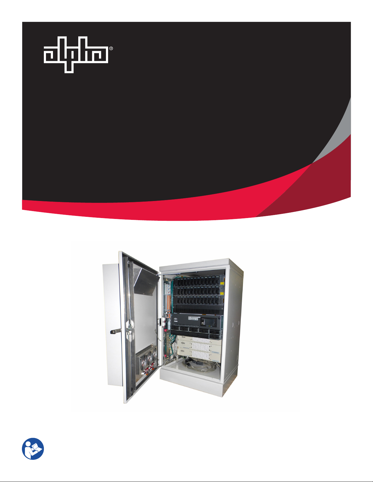
User Guide CPH-144 Central Power Hub
Contents
1. Safety......................................................................................................................... 5
1.1 Safety symbols..................................................................................................................................................................5
1.2 General warning and cautions..........................................................................................................................................5
1.3 Mechanical safety.............................................................................................................................................................6
1.4 Electrical safety.................................................................................................................................................................6
2. Overview.................................................................................................................... 7
3. Specifications ............................................................................................................ 8
4. Features..................................................................................................................... 9
4.1 Cordex® CXPS-E3 400A power system ............................................................................................................................9
4.2 Cordex® HP LPS36 up-converter......................................................................................................................................10
4.3 Cordex® CXC HP system controller .................................................................................................................................11
4.4 High voltage 50-pair protector panels ............................................................................................................................12
4.5 External AC loadcenter ...................................................................................................................................................12
4.6 48 Vdc heat exchanger....................................................................................................................................................13
5. Inspection ................................................................................................................ 14
5.1 Packing materials............................................................................................................................................................14
5.2 Returns for service ..........................................................................................................................................................14
5.3 Check for damage ...........................................................................................................................................................14
5.4 General receipt of shipment ...........................................................................................................................................14
5.5 Miscellaneous small parts..............................................................................................................................................14
6. Installation............................................................................................................... 15
6.1 Safety precautions ..........................................................................................................................................................15
6.2 Installation tools .............................................................................................................................................................15
6.3 Site selection ..................................................................................................................................................................15
6.4 Lifting ..............................................................................................................................................................................15
6.5 Mounting the enclosure..................................................................................................................................................16
7. Wiring...................................................................................................................... 18
7.1 Grounding the enclosure.................................................................................................................................................18
7.2 Internal wiring configurations of enclosure master ground bar .....................................................................................20