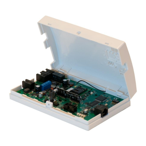
alphatronics AlphaCom PSTN-2-IP ML User manual

PSTN-2-IP ML
Installation
Manual

Service manual AlphaCom PSTN2IP ML transceiver Rev. 1.6 10-09-2011 Page 2/65
Technical specifications of the AlphaCom PSTN2IP ML transceiver:
Dimensions: 157 x 96 x 18 mm (l x w x h).
Power consumption standby: 115mA.
Power consumption operational: 210mA.
Power supply: 12-16 Volt dc
Operating temperature: 0- +50 C
LAN connection: 10 Mbit/s
Ordering code: 003611
The AlphaCom PSTN2IP ML transceiver complies with the following European standards:
EMC immunity EN50130-4 2003
Radio EN300220-3
Telephone TBR21 1998*)
Security Class European norm EN60950
Alarm transmission EN50136-2-1 1998
ATS classes 50136-1-1 D4, M4, T5, A3, S2, I3**)
*) the PSTN connection complies with the TBR21 norm, but is not connected to the public telephone
exchange network. The PSTN connection generates its own telephone line signals that imitate the signals of
a public exchange network, this makes it possible to receive alarm messages from the control panel that is
connected tot the PSTN connection and send them through an IP connection.
**) see chapter „Settings according to local requirements‟ for the correct settings of this device according to
the required local regulations for this specific installation. Also here you will find the settings for the dutch
regulations according to the AL1, AL2 and AL3 norm.
The AlphaCom PSTN2IP ML is manufactured with the most modern production methods and complies with
RoHS regulations. This means that components used and the soldering procedures are lead-free.
Alphatronics b.v.
Watergoorweg 71
3861 MA Nijkerk
The Netherlands
Telephone: +31 33-2459944
Fax: +31 33-2453149
Web: www.alphatronics.nl
E-mail: info@alphatronics.nl

Service manual AlphaCom PSTN2IP ML transceiver Rev. 1.6 10-09-2011 Page 3/65
TABLE OF CONTENTS
INTRODUCTION...........................................................................................................................................................4
GENERAL .......................................................................................................................................................................5
SETTINGS ACCORDING TO LOCAL REQUIREMENTS...................................................................................6
Forcing an alarm message manually........................................................................................................................6
Dutch regulations AL1, AL2 and AL3....................................................................................................................6
QUICK INSTALLATION GUIDE ..............................................................................................................................8
HARDWARE INSTALLATION................................................................................................................................10
PSTN tamper loop....................................................................................................................................................10
PSTN2IP ML PROGRAMMING...............................................................................................................................13
Log in .........................................................................................................................................................................18
Ethernet Settings..........................................................................................................................................................21
Webserver configuration .........................................................................................................................................22
Transceiver settings..................................................................................................................................................23
Monitoring Settings / Fault relay............................................................................................................................26
PSTN Interface Settings ..........................................................................................................................................28
Serial port configuration..........................................................................................................................................30
Factory Defaults........................................................................................................................................................32
ALPHACOM PSTN2IP ML PROGRAMMING WITH A DTMF-TELEPHONE.............................................34
OPERATION OF THE PSTN2IP ML.......................................................................................................................37
Transceiver 1 Backup function...............................................................................................................................37
Transceiver 2 as Double report function...............................................................................................................37
PSTN back-up function ...........................................................................................................................................38
LED indications on the PSTN2IP ML...................................................................................................................38
DIPSWITCH settings of the PSTN2IP ML..........................................................................................................40
New firmware flashen in the AlphaCom PSTN2IP ML (bios flash)................................................................41
APPENDIX A: Installing the FLASH software........................................................................................................48
APPENDIX B: DHCP server reservations................................................................................................................55
APPENDIX C: Cable wiring.......................................................................................................................................57
APPENDIX D: Reserved Port numbers.....................................................................................................................58
APPENDIX E: Explanatory notes ..............................................................................................................................59
APPENDIX F: Compatible control panels................................................................................................................62
APPENDIX G SIA-codes ............................................................................................................................................63
APPENDIX H: Release notes......................................................................................................................................64
REGISTER.......................................................................................................................................................................64
FIGURES
Figure 1: PSTN2IP ML transceiver..........................................................................................................4
Figure 2: PSTN2IP ML circuit board layout...........................................................................................10
Figure 3: Schematics PSTN tamper loop................................................................................................11
Figure 4: Jumper for PSTN tamper loop.................................................................................................11
Figure 3: LED and connector locations ..................................................................................................38
Figure 4: Connections for flash-mode (bios-update)................................................................................44
Figure 5: Jumpers in the „run-mode‟ ......................................................................................................47
Figure 4: Cross-over cable wiring..........................................................................................................57
Figure 5: Straight through cable wiring..................................................................................................57

Service manual AlphaCom PSTN2IP ML transceiver Rev. 1.6 10-09-2011 Page 4/65
INTRODUCTION
With the rapid expansion of broadband and Voice over IP connections in homes and businesses, alarm
transmissions for burglary systems are often overlooked. In most cases, the regular PSTN modem dialler of
the control panel will no longer be able to transmit its messages to the monitoring station. The AlphaCom
PSTN2IP ML transceiver is designed as an intelligent interface between control panels and the Internet. The
AlphaCom PSTN2IP ML offers the possibility to transmit messages via the Internet Protocol (IP) to receiver
equipment at the monitoring station in a safe and easy way.
The AlphaCom PSTN2IP ML transceiver can be used in combination with virtually any alarm control panel
supplied with an analogue alarm transmitter (PSTN dialler). The most common used protocols SIA-HA,
SIA, XSIA, Contact ID, Scancom slow (1400 Hz) and Scancom Fast (1600 Hz) are supported and can be
transmitted problem-free to a monitoring station using a standard broadband Internet connection.
The AlphaCom PSTN2IP ML is based on the same platform as the AlphaCom XL. The AlphaCom
PSTN2IP ML has the following features
PSTN line input (to receive dialer protocols)
LAN connection
Serial connection (for transparent RS-232 over IP)
RS-485 bus (for AlphaVision / AlphaHome / AlphaBox)
Tamper switch
PSTN tamper loop
Programming option via DTMF telephone
Power connection
The programming and functionality of the AlphaCom PSTN2IP ML and the AlphaCom XL are identical,
besides the fact that the PSTN2IP ML has less hardware present.
Figure 1: AlphaCom PSTN2IP ML transceiver

Service manual AlphaCom PSTN2IP ML transceiver Rev. 1.6 10-09-2011 Page 5/65
The text and illustrations used in this manual are based on the (kernel) firmware version 1.0 of the 19th of
December 2007.
GENERAL
The AlphaCom PSTN2IP ML is an alarm interface used to transmit alarm messages via IP to one or more
central stations.
The AlphaCom PSTN2IP ML can receive /generate messages from:
The PSTN connection
The serial connection (client-specific-application)
Internal (for example the tamper switch)
and can buffer these messages in an event buffer of maximum 100 messages. In the case that there are more
than 100 messages in the event buffer, then the oldest message will be erased and the new message will be
added (last in –first out).
From the buffer the AlphaCom PSTN2IP ML will transmit the message(s) to one of more central stations.
*) the serial connection is reserved for special applications and is not part of the standard AlphaCom
PSTN2IP ML specifications.
The AlphaCom PSTN2IP ML can be set-up and configured via a web interface. The set-up and
configuration is explained in the following pages.
PSTN input
Serial input*)
Internal
systems
Event buffer
(Max. 100 events.)
Dialer 1
Dialer 2
Standard
connection
Backup
connection
Standard
connection
Backup
connection

Service manual AlphaCom PSTN2IP ML transceiver Rev. 1.6 10-09-2011 Page 6/65
SETTINGS ACCORDING TO LOCAL REQUIREMENTS
The AlphaCom PSTN2IP ML can be used in various different applications. In installations were local or
European regulations apply (for instance EN50136-1-1 and EN50136-2-1) we strongly advise to take the
following into consideration:
Access to the web interface must be secured with a username and password. The password chosen must not
be a simple and easy password and it is advised to always use a combination of digits and letters.
After installing and programming the AlphaCom PSTN2IP ML dipswitch 3 must be set to OFF to make it
impossible to access the web interface remotely. See page 40 for an overview of dipswitch settings.
The AlphaCom PSTN2IP ML must be placed in a casing which complies to regulations and the security
class specified by local regulations. The AlphaCom PSTN2IP ML does not include a GPRS option and can
therefore not be installed in installations requiring grade 4. In these situations a AlphaCom XL can be used.
The PSTN line supervision should be enabled (see page 11 and 30)
The security settings for the PSTN priority switch must be enabled to ensure that the control panel detects
the disappearance of the analog telephone line if the IP connection for transceiver 1 or 2 fails or disappears.
Forcing an alarm message manually
According to the 50136-2-1 is must be possible to create an alarm message manually. When using the
AlphaCom PSTN2IP ML the analog dialer of the control panel is connected to the PSTN input. If the dialler
or control panel has the possibility of forcing an alarm message manually, the AlphaCom PSTN2IP ML
complies with the regulations.
In all other cases it is advised to program the tamper switch on the AlphaCom PSTN2IP ML to cause an
alarm when it is opened.
Dutch regulations AL1, AL2 and AL3
In the Netherlands local regulations require the security industry to work with security classes which have
been designed according to the European norm EN50131 and EN50136. Depending on the specified risk
class, various rules and regulations apply. These rules and regulations also include the type of alarm
transmission that must be used.
A simple overview of the security class is as follows:
Residential
Security Class
Regulations for Alarming / transmission
1
none (also known as AL0)
2
AL1
3
AL1
4
AL2

Service manual AlphaCom PSTN2IP ML transceiver Rev. 1.6 10-09-2011 Page 7/65
Industry
Security Class
Regulations for Alarming / transmission
1
AL1
2
AL1
3
AL1
3*
AL2
4
AL2
4*
AL3
Alarm transmission
AL0
None
AL1
Alarm transmission according to NEN EN 50136-1-
1 level AL1
AL2
Alarm transmission according to NEN EN 50136-1-
1 level AL2
AL3
Alarm transmission according to NEN EN 50136-1-
1 level AL2 accompanied with a back-up
transmission channel according to level AL1 via a
different transmission method (for example GPRS)
The above information is based on the „Verbeterde Risicoklassenindeling VRKI 2007‟. For a full overview,
see www.hetccv.nl.
If all parameters have been set correctly the AlphaCom PSTN2IP ML can be used in AL0, AL1 and
AL2 situations. Voor AL3 situations a AlphaCom XL with a GPRS module must be used.
According to the EN50136-1-1 there are specific rules and regulations that also apply for alarm transmission
over IP. The AlphaCom XL complies with regulations: D4, M4, T5, A3, S2, I3. A higher number indicates a
better performance.
The regulations for AL1 are: T2, T2, T2, D2, M2, S1, I2.
The regulations for AL2 are: T4, T2, T3, D3, M3, S2, I3
The regulations for AL3 are: primary transmission AL2 + back-up AL1 (only AlphaCom XL!)
Most of the features of the AlphaCom PSTN2IP ML with respect to the above mentioned information are
determined by the hardware design. It is therefore not necessary to fill in specific parameters to comply. The
only point of consideration is the Supervision Interval (polling time) and the periodic testmessage, see
Configuration IP dialer.
It is strongly recommended when using AL1 to program the Supervision Interval to a value not higher than
900 (15 minutes) and for AL2 no higher than 90 seconds.
The Periodic Testmessage is the automatic test message generated by the AlphaCom itself. In the Standard
Settings this is not necessary. When the AlphaCom PSTN2IP ML is used in a AL2 application this value
must be programmed in the Backup Settings to 1440 minutes (the regulation states less than 1x per 25
hours).

Service manual AlphaCom PSTN2IP ML transceiver Rev. 1.6 10-09-2011 Page 8/65
QUICK INSTALLATION GUIDE
The most common situation in which the AlphaCom PSTN2IP ML transceiver can be placed is a home
situation: the residents have an existing alarm installation and decide to switch over to Voice over IP (VoIP)
via a cable or ADSL connection. The consequence of this is that the alarm control panel no longer will be
able to send its messages to the monitoring station. By using the AlphaCom PSTN2IP ML transceiver, the
existing alarm installation can still be used and the alarm messages can be send reliably to the monitoring
station using an Internet connection.
The AlphaCom PSTN2IP ML transceiver is delivered complete in a synthetic casing and is ready to use. In
most cases, the transceiver can be mounted, connected and set up immediately.
Preparation
Make sure the following components are available before installation:
-Alarm control panel with an analog dialler
-12VDC power supply from the control panel
-Router or switch with a free LAN connection
-Working Internet connection
-Computer / Laptop with Internet Explorer *) version 6 or 7 or compatible browser. In this manual a
computer with Windows 2000 or Windows XP is used.
-Cross-over network cable for programming
*) Attention: Internet Explorer 5.0 (or lower) is not supported!
Also, make sure the following information is known:
-The protocol used by the analog dialer of the alarm control panel
-The IP address and the registration port of the RC-4001 IP receiver card or RX-5000 receiver at the
monitoring station
-The IP address of the (local) Gateway which has to be programmed in the AlphaCom PSTN2IP ML
-The subnet mask of the local network
Mounting
-It is advised to place the AlphaCom PSTN2IP ML in the cabinet of the control panel. The control
panel must have a proper earth connection.
-If the control panel‟s dialler is still connected to a telephone line (or VoIP), remove this connection.
-Connect the control panels dialer to the PSTN input on the AlphaCom PSTN2IP ML.
Attention: the cable between the dialler and AlphaCom PSTN2IP ML must not exceed 30m.
-Next, connect a Cross-over network cable to the LAN connection of the AlphaCom PSTN2IP ML
and to the LAN connection of a laptop.
- Set dipswitches 2*) **)and 3 **) to ON.
-Connect a 12VDC power supply from the control panel to the AlphaCom PSTN2IP ML transceiver.
*) Dipswitch 2 set to ON allows logging in by entering the standard login name (admin) and no
password. Dipswitch 2 can remain OFF when a login name and password is already programmed.
**) For a complete list of dipswitch settings see chapter dipswitch settings.

Service manual AlphaCom PSTN2IP ML transceiver Rev. 1.6 10-09-2011 Page 9/65
AlphaCom PSTN2IP ML PROGRAMMING
The AlphaCom PSTN2IP ML can now be programmed. Set the laptop‟s IP address to 192.168.0.49 and the
subnet mask to 255.255.255.0. The gateway address can be left empty.
Now start up your Internet browser and type in the address field 192.168.0.48. The login screen will now
appear. Follow the programming instructions as described at page 13.
Set dipswitches 2 and 3 back after programming and connect a standard (straight) network cable between the
AlphaCom PSTN2IP ML and the router. Reset the AlphaCom PSTN2IP ML by removing the power
connector or by shorting the reset pins. Do not forget to test the reporting to the monitoring station.

Service manual AlphaCom PSTN2IP ML transceiver Rev. 1.6 10-09-2011 Page 10/65
HARDWARE INSTALLATION
Figure 2: AlphaCom PSTN2IP ML circuit board layout
The AlphaCom PSTN2IP ML transceiver can be supplied with power in two ways: with the 2,1 mm jack
connection (+ in the middle), or directly on the + and 0V terminals of the RS-485 bus connection.
Attention: when the AlphaCom PSTN2IP ML is connected to the RS-485 bus, a choice must be made for the
following:
Either the AlphaCom PSTN2IP ML is powered through the RS-485 bus. This is the most common
situation.
Or the AlphaCom PSTN2IP ML is powered by an external power supply through the 2,1mm jack
connection. This is not common when also connecting to the RS-485 bus. If this is however the
case then only the A, B and 0V wires of the RS-485 bus must be connected !.
The analog dialer of the control panel is connected to the alarm dialler RJ-11 input (marked with CMK).
Only the two middle wires (2 and 3) are used.
PSTN tamper loop
The AlphaCom XL is equipped with an option to monitor the cable connection between the analog dialer of
a control panel and the PSTN input. To use this option jumper J19 must placed across pins 1 and 2. The
outer 2 wires (1 and 4) of the telephone cable are used. Both wires 1 and 4 should be connected together on
the side of the dialer in the control panel. To clarify the tamper loop solution see the schematics below:
Backup Telephone
line connection
Dialler
connection
RS-485 Bus
12VDC jack
power adapter
LAN
connection

Service manual AlphaCom PSTN2IP ML transceiver Rev. 1.6 10-09-2011 Page 11/65
Figure 3: Schematics PSTN tamper loop
Jumper J19 is easy to find using the picture below:
Figure 4: Jumper for PSTN tamper loop
To enable the PSTN tamper loop option jumper J19 must be placed over pin 1 and pin 2. This can be done
by moving the jumper of J19, which is situated directly next to the priority relay. The most upper pin (pin 3)
on J19 must be left open.
Also the PSTN tamper loop option must be enabled in the software. See programming PSTN interface.
The backup telephone line output (TEL) can be used to connect an external PSTN line or external GSM
interface. This connection can be used for backup purposes, in case the IP connection with the monitoring
station fails.
J19 is to select the PSTN tamper loop option.
Pin 3 of the schematics (0V) is the top pin of
the 3.

Service manual AlphaCom PSTN2IP ML transceiver Rev. 1.6 10-09-2011 Page 12/65
The difference with an integrated GSM module (like in the AlphaCom XL GPRS) and an external GSM
interface is that the external GSM interface uses a GSM audio connection to transmit the original PSTN
protocol via a GSM (audio) connection to the central station. The integrated GPRS (IP over GSM) modules
sends data packages over GPRS to the central station and more advanced and more reliable.
Finally a LAN connection has to be made. Connect the AlphaCom PSTN2IP ML to a free LAN output of a
router or switch. The ALPHACOM XL uses a 10Mbit/s connection and it is preferred to use a “straight
through” CAT5 cabling. When making a custom-made LAN cable, it is strongly recommended to use the
standard color scheme for the wiring, see appendix B.

Service manual AlphaCom PSTN2IP ML transceiver Rev. 1.6 10-09-2011 Page 13/65
AlphaCom PSTN2IP ML PROGRAMMING
The AlphaCom PSTN2IP ML can be programmed through an Internet browser or by means of a DTMF-
telephone. See chapter „AlphaCom PSTN2IP ML programming with a DTMF telephone (page. 34) to
program the AlphaCom PSTN2IP ML with a DTMF telephone or follow the instructions below to program
the AlphaCom PSTN2IP ML with an internet browser.
When programming the AlphaCom PSTN2IP ML for the first time, dipswitch 1 must be set to ON before
applying power to the unit. After applying power to the unit the factory default settings will be programmed
into the AlphaCom PSTN2IP ML. Set dipswitch 1 back to the “normal” position OFF.
When the AlphaCom PSTN2IP ML is programmed for the first time, dipswitch 2 must be set to ON (before
applying power) to force IP address 192.168.0.48 with web port 80 to be used. The „username‟ is „admin‟
and no password is needed to login. Use this procedure only to program the personal Ethernet settings
and username and password settings only. After doing this reset the AlphaCom PSTN2IP ML and set
dipswitch 2 to OFF.
With dipswitch 2 you can always enter the programming without the need for a valid user name.
Attention: when setting dipswitch 2 to ON you can gain access to the programming without entering a
username and password. Dipswitch 2 can stay OFF if you have already set a new username and password.
Use dipswitch 2 only to gain access to the programming and set the username, password and Ethernet
settings. After programming these settings, restart the AlphaCom PSTN2IP ML and set dipswitch 2 to OFF.
When the AlphaCom PSTN2IP ML is programmed for the first time, it must be connected directly to a
computer using a crossover cable. In this case, the computer has to be set up to use a fixed IP address, for
example 192.168.0.49 and subnet mask 255.255.255.0.
Dipswitchs

Service manual AlphaCom PSTN2IP ML transceiver Rev. 1.6 10-09-2011 Page 14/65
To set-up the fixed IP address, go to Start, Control Panel and open the Dial up and Network connections.
The present network connections will now appear on the screen.
Right click on the active LAN connection and open the properties menu. The characteristics of this LAN
connection will be shown on screen:

Service manual AlphaCom PSTN2IP ML transceiver Rev. 1.6 10-09-2011 Page 15/65
Select „Internet-protocol TCP/IP‟ and click „Properties‟. The following screen will appear:
Select the option „Use the following IP address‟ and enter 192.168.0.49 at the IP-address field and
255.255.255.0 at the subnet mask field. The default gateway field can be left empty. Press OK to save the
changes.

Service manual AlphaCom PSTN2IP ML transceiver Rev. 1.6 10-09-2011 Page 16/65
Programming the AlphaCom PSTN2IP ML can be done using a commonly used web browser. Supported
versions are Internet Explorer*) (versions 6 and 7), Mozilla Firefox (version 1.5) and Opera (version 8.5).
*) Attention: Internet Explorer 5.0 (or lower) is not supported!
Before programming, the dipswitches on the AlphaCom PSTN2IP ML have to be set to the correct
positions.
Set dipswitch 1 to OFF to ensure that the factory defaults are not set.
Set dipswitch 2 to OFF to use the programmed login name with password and also the programmed
IP address / webserver port. Dipswitch 2 determines whether or not the AlphaCom PSTN2IP ML
requires a valid login name or password and IP settings or whether the standard login name (admin)
without password is used and the fixed IP address 192.168.0.48 with web port 80.
Set dipswitch 3 to ON so the AlphaCom PSTN2IP ML can be reached via a standard web-browser.
If dipswitch is 3 is set to OFF the AlphaCom PSTN2IP ML cannot be reached in anyway via a web-
browser.
Ensure dipswitch 4 is set to OFF.
*) Set dipswitch 2 to ON only to program the username, password and Ethernet settings. Restart the
AlphaCom PSTN2IP ML and set dipswitch 2 to OFF after programming these parameters.
Attention: in this manual the standard IP address is 192.168.0.48 and web port 80.
When the dipswitches are set correctly, use the browser to open http://192.168.0.48 (or the IP address that is
already programmed into the AlphaCom PSTN2IP ML). Remember to type in only http://192.168.0.48,
without „www‟. If required, the used port number can be placed behind the IP address, as such:

Service manual AlphaCom PSTN2IP ML transceiver Rev. 1.6 10-09-2011 Page 17/65
192.168.0.48:81. The :81 is used to force the browser to use port 81 and only needs to be used when
dipswitch 2 is set to OFF.
Please note: In Internet Explorer, for „normal‟ web pages, using web port 80, it is not necessary to type in
http:// but when using another web port, like 81, it is necessary!
Web Port 80 is the standard HTTP port, meaning it can always be reached, regardless of the used router or
firewall. This is the reason for using port 80 in the AlphaCom PSTN2IP ML when dipswitch 2 is set to ON.
Since this is not the safest port, make sure to program the used port in the AlphaCom PSTN2IP ML to a
different one. The default port setting with dipswitch 3 set to OFF is port 80. This means when no other port
is programmed, the AlphaCom PSTN2IP ML can only be reached on port 80. It is recommended to use port
81 or 82.
Attention: when dipswitch 2 is in the OFF position and the AlphaCom PSTN2IP ML has been restarted, the
AlphaCom PSTN2IP ML can only be reached by using the programmed web port.
Attention: if it is necessary to reach the AlphaCom PSTN2IP ML from a remote location and the web
server port has been to 81, then port 81 must also be opened in the modem/router.
Hint: to check if the computer can reach the AlphaCom PSTN2IP ML, the PING command can be used.
This command can be executed in a DOS prompt. Also the computer‟s IP configuration can be displayed
easily by using the IPCONFIG command. To open a DOS prompt, go to Start, Execute and enter „cmd‟ at
the command line:

Service manual AlphaCom PSTN2IP ML transceiver Rev. 1.6 10-09-2011 Page 18/65
This opens a DOS screen, which, among other things, can be used to ping a certain IP address:
C:\>ping 192.168.0.48
Pinging 192.168.0.48 with 32 bytes of data:
Reply from 192.168.0.48: bytes=32 time=4ms TTL=100
Ping statistics for 192.168.0.48:
Packets: Sent = 4, Received = 4, Lost = 0 (0% loss),
Approximate round trip times in milli-seconds:
Minimum = 4ms, Maximum = 4ms, Average = 4ms
The IPCONFIG command can be used to show information of the PC’s network configuration:
C:\>IPCONFIG
Windows 2000 IP Configuration
Ethernet adapter Local Area Connection:
Connection-specific DNS Suffix . :
IP Address. . . . . . . . . . . . : 192.168.0.49
Subnet Mask . . . . . . . . . . . : 255.255.255.0
Default Gateway . . . . . . . . . : 192.168.0.16
To see even more information, the command ipconfig/all can be used.
Log in
After the correct IP address of the AlphaCom PSTN2IP ML has been entered in the browser, the following
screen will appear:

Service manual AlphaCom PSTN2IP ML transceiver Rev. 1.6 10-09-2011 Page 19/65
As long as dipswitch 2 is set to ON, the AlphaCom PSTN2IP ML does not require a valid password, the
password field can be left empty.
The supervisor (standard username „admin‟, no standard password) can view and edit all configuration
setting and view the status information
If a wrong combination of username and password is entered to many times, access to the web interface is
blocked and messages are ignored. For detailed explanation of the web server configuration see page 17.
After pressing the OK button, the status screen is displayed
(If an invalid username and password is entered the login screen will appear again)

Service manual AlphaCom PSTN2IP ML transceiver Rev. 1.6 10-09-2011 Page 20/65
After logging is as the supervisor (admin) the status screen is shown on your screen. This is a summary of all
statuses of the AlphaCom PSTN2IP ML. By using the menu buttons on the left hand side of the screen you
can access certain programming options. The various menus will be explained in the following pages of the
manual.
The status screen is automatically refreshed every 10 seconds
Possible messages for the transceiver:
Disabled: The transceiver has not been configured
Not in use: The transceiver is assumed to be programmed as a backup transceiver and is not operational
yet..
Busy: The transceiver is busy making a connection or sending a message.
Ready: The connection is operational. There are no messages in the buffer.
Error: There has been no connection with the central station for longer than 90 seconds.
This manual suits for next models
1
Table of contents
Other alphatronics Transceiver manuals