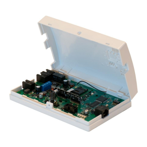
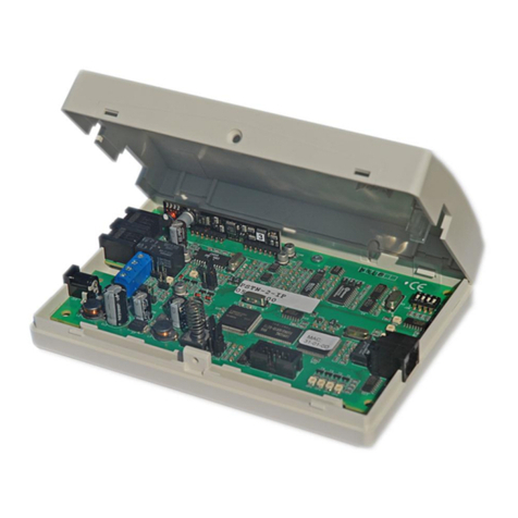
alphatronics AlphaCom XL User manual

Alphatronics bv * Watergoorweg 71* 3861MA Nijkerk * Tel.: 033-2459944 * Fax.: 033-2453149 * [email protected]
XL Transceiver
Service
Manual

Service manual AlphaCom XL transceiver Rev. 1.4 10-08-2011 Blz. 2/74
Technical details for the AlphaCom XL transceiver:
Dimensions: 163 x 92 x 18 mm (l x w x h).
Currentdrain active: 135mA. (no GPRS) *)
Currentdrain peek: 275mA. (no GPRS) *)
Currentdrain active: 145mA. (incl. GPRS) **)
Currentdrain peek: 385mA. (incl. GPRS)**)
Power supply: 12-16VDC
Working temperature: 0 tot +50 C
Humidity: max. 85% relative humidity
LAN connection: 10 Mbit/s
Articlecode: 003630
Technical details regarding relay outputs. Details which are based on outputs 2, 3 and 4, which can be
activated by the user remotely, are not part of the security concept and were not subject to official testing by
the testing authorities. It is highly recommended to power external devices through an external power supply
and thus not draining cuurent from the AlphaCom XL transceiver.
Currentdrain relay 2 to 4: 65mA (active).
Maximum current drain: 500mA (+12V terminal to relay 4)
*) no GPRS means, that the GPRS transceiver is not programmed. The GPRS module is present on the pcb
board, but not active.
**) incl. GPRS means, that the GPRS transceiver has been programmed and the GSM module is enrolled in
the GPRS network. The module is stand-by and waiting to send a message.
De ALPHACOM XL transceiver complies with the following European regulations:
EMC emission EN301489-3 2002
EMC immunity EN50130-4 2003
Radio transmission EN300220-3
Telephone TBR21 1998*)
Safety class European norm EN60950
Alarm transmission EN50136-2-1 1998
ATS classes 50136-1-1 D4, M4, T5, A3, S2, I3**)
*) the PSTN connection complies with the TBR21 norm, but is not connected to any public telephone system
or public telephone network. The PSTN connection generates its own signals to simulate a public telephone
exchange, so alarm messages sent by the analog dialer of the security alarm system, can be received and sent
via an IP connection.
**) see chapter „Settings according to local requirements‟ for the correct settings of this device according to
the required local regulations for this specific installation. Also here you will find the settings for the dutch
regulations according to the AL1, AL2 and AL3 norm.
The AlphaCom XL is manufactured according to the most modern production methodes and complies with
RoHS standards. This means that the components used and the soldering process are lead-free.

Service manual AlphaCom XL transceiver Rev. 1.4 10-08-2011 Blz. 4/74
TABLE OF CONTENTS
INTRODUCTION............................................................................................................................................7
GENERAL........................................................................................................................................................8
SETTINGS ACCORIDNG TO LOCAL REQUIREMENTS ..........................................................................9
Forcing an alarm message manually........................................................................................................................9
Dutch regulations AL1, AL2 and AL3....................................................................................................................9
QUICK INSTALLATION GUIDE ................................................................................................................11
ALPHACOM XL PROGRAMMING ............................................................................................................12
HARDWARE INSTALLATION ...................................................................................................................13
PSTN tamper loop....................................................................................................................................................14
Analog inputs............................................................................................................................................................15
Relay outputs.............................................................................................................................................................16
Connecting serial logprinter from control panel ..................................................................................................18
ALPHACOM XL PROGRAMMING ............................................................................................................20
Alphatronics Equipment Discovery Tool..............................................................................................................24
Log in .........................................................................................................................................................................24
Status screen..............................................................................................................................................................26
Ethernet configuration..............................................................................................................................................27
GPRS / GSM configuration.....................................................................................................................................29
Webserver configuration .........................................................................................................................................31
Configuration IP transceiver 1................................................................................................................................33
Configuration IP transceiver 2................................................................................................................................34
Monitoring Settings / Fault relay............................................................................................................................35
Configuration inputs 1 to 6..........................................................................................................................................36
PSTN interface configuration.................................................................................................................................38
Serial port configuration..........................................................................................................................................40
Relay output configuration......................................................................................................................................43
Restore Factory Default Settings............................................................................................................................44
Relay control by user ...............................................................................................................................................46
TESTING THE ALPHACOM XL.................................................................................................................47
Back-up function of transceiver 1..........................................................................................................................47
Transceiver 2 as dual transmission.........................................................................................................................47
PSTN back-up function ...........................................................................................................................................48
LED indications on the PSTN-2-IP........................................................................................................................48
DIPSWITCH settings of the AlphaCom XL ........................................................................................................49
Firmware upgrade for the AlphaCom XL (bios flash)........................................................................................50
APPENDIX A Installing the FLASH program...............................................................................................57
APPENDIX B Making a reservation on a DHCP server................................................................................64
APPENDIX C Cable wiring........................................................................................................................... 66
APPENDIX D Reserved port numbers...........................................................................................................67
APPENDIX E.................................................................................................................................................68
APPENDIX F Compatible control panels ...................................................................................................... 71
APPENDIX G SIA-codes............................................................................................................................... 72
APPENDIX H Release notes..........................................................................................................................73
REGISTER.....................................................................................................................................................73
ILLUSTRATIONS
Figure 1: AlphaCom XL transceiver........................................................................................................7
Figure 2: AlphaCom XL connections.....................................................................................................13
Figure 3: Schematics PSTN tamper loop................................................................................................14

Service manual AlphaCom XL transceiver Rev. 1.4 10-08-2011 Blz. 5/74
Figure 4: Jumper for PSTN tamper loop.................................................................................................14
Figure 5: Jumper settings for relay.........................................................................................................16
Figure 3: Connection serial logprinter to AlphaCom XL .........................................................................18
Figure 4: Serial cable from logprinter to AlphaCom XL..........................................................................18
Figure 6: Connections.for flashing firmware (bios-update)......................................................................53
Figure 6: Straight through cable wiring..................................................................................................66
Figure 7: Netwerk cross-over cable wiring.............................................................................................66

Service manual AlphaCom XL transceiver Rev. 1.4 10-08-2011 Blz. 6/74

Service manual AlphaCom XL transceiver Rev. 1.4 10-08-2011 Blz. 7/74
INTRODUCTION
With the rapid expansion of broadband and Voice over IP connections in homes and businesses, alarm
transmissions for burglary systems are often overlooked. In most cases, the regular PSTN modem dialer of
the control panel will no longer be able to transmit its messages to the monitoring station. The ALPHACOM
XL transceiver is designed as an intelligent interface between control panels and the Internet. The
ALPHACOM XL offers the possibility to transmit messages via the Internet Protocol (IP) to receiver
equipment at the monitoring station in a safe and easy way.
The ALPHACOM XL transceiver can be used in combination with virtually any alarm control panel
supplied with an analog alarm transmitter (PSTN dialer). The most common used protocols SIA-HA, SIA,
XSIA, Contact ID, Scancom slow (1400 Hz) and Scancom Fast (1600 Hz) are supported and can be
transmitted without any problems to a monitoring station using a standard broadband Internet connection.
If the AlphaCom XL does not succeed to send alarm messages through the hardwired LAN connection, the
AlphaCom XL has the possibility to send the alarm messages through the integrated GPRS-module. The
AlphaCom XL can also be used in locations were there is no hardwired LAN connection, in this case the
GPRS-module is used as the primary transmission device.
Figure 1: AlphaCom XL transceiver
The text and illustrations in this manual are based on firmware version 1.7 of the 18th of may 2009.

Service manual AlphaCom XL transceiver Rev. 1.4 10-08-2011 Blz. 8/74
GENERAL
The AlphaCom XL is an alarm interface used to transmit alarm messages via IP to one or more central
stations.
The AlphaCom XL can receive /generate messages from:
The PSTN connection
The 12 inputs
The serial connection, RS-485 bus and client-specific-application
Internal (for example the tamper switch)
and can buffer these messages in an event buffer of maximum 100 messages. In the case that there are more
than 100 messages in the event buffer, then the oldest message will be erased and the new message will be
added (last in –first out).
From the buffer the AlphaCom XL will transmit the message(s) to one of more central stations.
*) the existing firmware includes some special functions, like the support of the AlphaVision NG bus (RS-
485) and general printer output support (for instance compatible with Galaxy control panels).
The AlphaCom XL can be setup and configured via a web interface. The setup and configuration is
explained in the following pages.
Inputs
PSTN input
RS-232
RS-485*)
Internal
system
Event buffer
(100 events max.)
Dialer 1
Dialer 2
Standard
connection
Backup
connection
Standard
connection
Backup
connection

Service manual AlphaCom XL transceiver Rev. 1.4 10-08-2011 Blz. 9/74
SETTINGS ACCORDING TO LOCAL REQUIREMENTS
The AlphaCom XL can be used in various different applications. In installations were local or European
regulations apply (for instance EN50136-1-1 and EN50136-2-1) we strongly advise to take the following
into consideration:
Access to the web interface must be secured with a username and password. The password chosen must not
be a simple and easy password and it is advised to always use a combination of digits and letters.
After installing and programming the AlphaCom XL dipswitch 3 must be set to OFF to make it impossible
to access the web interface remotely. See page 49 for an overview of dipswitch settings.
The AlphaCom XL must be placed in a casing which complies to regulations and the security class specified
by local regulations. If the AlphaCom XL is used including the GPRS option, then the AlphaCom can be
installed in installation up to grade 4.
The PSTN line supervision should be enabled (see page 13, 14 and 35)
Relay 4 (fault relay) should be programmed to be activated if a fault occurs in one of the transmission
channels. The relay should be connected to an input on the alarm control panel to activate an alarm.
Forcing an alarm message manually
According to the 50136-2-1 is must be possible to create an alarm message manually. In cases were a dialler
or control panel has been connected to the PSTN input and the dialler or control panel has the possibility of
forcing an alarm message manually, the AlphaCom XL complies with the regulations.
In all other cases it is advised to program the tamper switch on the AlphaCom XL to cause an alarm when it
is opened or to connect a push button to one of the inputs on the AlphaCom XL and program the necessary
input definitions.
Dutch regulations AL1, AL2 and AL3
In the Netherlands local regulations require the security industry to work with security classes which have
been designed according to the European norm EN50131 and EN50136. Depending on the specified risk
class, various rules and regulations apply. These rules and regulations also include the type of alarm
transmission that must be used.
A simple overview of the security class is as follows:
Residential
Security Class
Regulations for Alarming / transmission
1
none (also known as AL0)
2
AL1
3
AL1
4
AL2

Service manual AlphaCom XL transceiver Rev. 1.4 10-08-2011 Blz. 10/74
Industry
Security Class
Regulations for Alarming / transmission
1
AL1
2
AL1
3
AL1
3*
AL2
4
AL2
4*
AL3
Alarm transmission
AL0
None
AL1
Alarm transmission according to NEN EN 50136-1-
1 level AL1
AL2
Alarm transmission according to NEN EN 50136-1-
1 level AL2
AL3
Alarm transmission according to NEN EN 50136-1-
1 level AL2 accompanied with a back-up
transmission channel according to level AL1 via a
different transmission method (for example GPRS)
The above information is based on the „Verbeterde Risicoklassenindeling VRKI 2007‟. For a full overview,
see www.hetccv.nl.
If all parameters have been set correctly the AlphaCom XL can be used in all cases !. In a AL3 situation the
GPRS module must be present.
According to the EN50136-1-1 there are specific rules and regulations that also apply for alarm transmission
over IP. The AlphaCom XL complies with regulations: D4, M4, T5, A3, S2, I3. A higher number indicates a
better performance.
The regulations for AL1 are: T2, T2, T2, D2, M2, S1, I2.
The regulations for AL2 are: T4, T2, T3, D3, M3, S2, I3
The regulations for AL3 are: primary transmission AL2 + back-up AL1
Most of the features of the AlphaCom XL with respect to the above mentioned information are determined
by the hardware design of the AlphaCom XL. It is therefore not necessary to fill in specific parameters to
comply. The only point of consideration is the Supervision Interval (polling time) and the periodic
testmessage, see Configuration IP dialer.
It is strongly recommended when using AL1 to program the Supervision Interval to a value not higher than
900 (15 minutes) and for AL2 no higher than 90 seconds.
The Periodic Testmessage is the automatic test message generated by the AlphaCom itself. In the Standard
Settings this is not necessary. When the AlphaCom XL is used in a AL2 application this value must be
programmed in the Backup Settings to 1440 minutes (the regulation states less than 1x per 25 hours). This
setting will determine that the backup medium, even though it is not active, will send a message 1x per 24
hours. With this combination, the AlphaCom XL complies with even the highest level AL3.

Service manual AlphaCom XL transceiver Rev. 1.4 10-08-2011 Blz. 11/74
QUICK INSTALLATION GUIDE
The most simple situation were the ALPHACOM XL transceiver can be used is in the consumer market: the
homeowner has an existing alarm system en has decided to step over to Voice over IP (VoIP) instead of his
existing analog or ISDN telephone line. Due to the migration to VoIP the transmission of alarm messages
from his alarm system to the central station do not work correctly or are unreliable. By using the
ALPHACOM XL transceiver the existing alarm system can be left untouched and the alarm messages can be
transmitted to the central station in an efficient and reliable way.
The ALPHACOM XL transceiver is available in a pcb only version and also in a version in its own synthetic
casing including power supply and battery backup. Assuming we use the pcb only version, the ALPHACOM
XL can be mounted inside the casing of the alarm system, connected to a free LAN connection on your
router of switch and it is ready to be connected and programmed.
Preperation
Before installing please ensure the following components are present:
-Alarm system with analog dialer
-12VDC power supply from your alarm system
-Router or switch with a free LAN connection
-A working internet connection
-A Laptop
-A cross-over network cable for programming
Make sure the following details are available before you start installing:
-The protocol that the analog dialer of the alarm system uses
-The IP address and registration port of the RC-4001 IP receivercard or RX-5000 receiver in the
central station
-The IP address of the (local) Gateway that needs to be programmed in the ALPHACOM XL
-The subnet mask of the local network
Tip: instead of using a local IP address and a subnetmask, the AlphaCom XL can also be set to work with
DHCP (factory default). In this situation the AlphaCom XL will ask the DHCP server of the network to
provide it with an IP address and a subnetmask.
Mounting
-Mount the ALPHACOM XL in a metal casing using the plastic pcb studs. It is recommended to
mount the AlphaCom XL in the metal cabinet of the alarm system. The metal cabinet and ground
connection of the power supply (alarm system) should be connected to a clean earth connection.
-If the analog dialer is still connected to the analog telephone line (or VoIP), disconnect the telephone
line cable from the dialer.
-Connect the cable from the analog dialer of the alarm system to the CMK connection of
ALPHACOM XL transceiver (see figure 2 ,page. 13).
-Connect a Cross-over network cable to the LAN connection of the AlphaCom XL and the LAN
connection of your laptop.
- Set dipswitches 2*) **) and 3***) to ON.
-Power-up the ALPHACOM XL transceiver.
*) dipswitch 2 set to ON: Logging in is possible just by using the login-name (admin). Dipswitch 2 can be
set to OFF if the login name and password have already been set in the web browser.

Service manual AlphaCom XL transceiver Rev. 1.4 10-08-2011 Blz. 12/74
**) See „Dipswitch settings of the ALPHACOM XL‟ (page 49) for a complete overview of all the dipswitch
settings.
***) The AlphaCom XL is set to DHCP as factory default. If both AlphaCom XL and computer/laptop are
connected to the same network, the AlphaCom XL can be traced using the Alphatronics Equipment
Discovery Tool.
ALPHACOM XL PROGRAMMING
The ALPHACOM XL can now be programmed. Change the IP address of the laptop (for example) to
192.168.0.49 and the subnet mask to 255.255.255.0 (see page 7 for instructions hoe to set the IP address in
your laptop). The gateway address can be left empty.
Open your internet browser . Type in the IP addreess 192.168.0.48 in the browser screen. The log-in prompt
of the AlphaCom XL will now appear on your screen. Follow the programming instructions as mentioned
from page 9 onwards.
Set dipswitches 2 and 3 back to OFF after programming and connect a standard (straight) network cable
between the PSTN2IP and the router. Reset the PSTN2IP by removing the power connector or by shorting
the reset pins. Do not forget to test the reporting to the monitoring station.
Attention: the AlphaCom XL is set to DHCP by factory default. If both AlphaCom XL and computer/laptop
are connected to the same network, the AlphaCom XL can be traced using the Alphatronics Equipment
Discovery Tool.

Service manual AlphaCom XL transceiver Rev. 1.4 10-08-2011 Blz. 13/74
HARDWARE INSTALLATION
Figure 2: ALPHACOM XL connections
The AlphaCom XL transceiver is powered through the +-16VDC terminal blocks
Attention: when using the RS-485 bus you must take into consideration:
the AlphaCom XL receives is power supply through the -+16VDC connections. This is always the
case when the AlphaCom XL is delivered including power supply and batterypack in a synthetic
casing. In this case for the RS-485 bus connections only the 0V, A and B wires must be connected.
The +-terminal connection of the RS-485 bus must not be connected.
the AlphaCom XL is powered by the RS-485 bus.
DIP switch‟s
Backup Telephone line
connection
Alarmdialer
connection
GPRS module*)
Power supply
connection
LAN activity LED
(see LEDs)
LAN connection
4 Status LEDs
(see LEDs)
LAN Link LED
Trouble output
Watchdog LED
12 Analog inputs
GPRS LED
Jumpers t.b.v. ingangen
(spanning sturing ja/nee)
0V for analog inputs
+12V en 0V for relay
Tamper switch
Red LED: Priority switch
of the Alarm dialer
is active
RS-485 bus connection (serial port 2)
Jumpers for
firmware update
4x jumper to
select OC
output instead
of relay output
4x jumper to
connect C-
contact of the
relay with +12V
RS-232 for flashing firmware(serial port 1)
Jumper for PSTN
tamper loop
3 relay or OC
outputs
RS-485 master/slave:
remove when using in
combination with
AlphaVision NG
RS-232 (serial port 3)

Service manual AlphaCom XL transceiver Rev. 1.4 10-08-2011 Blz. 14/74
The analog dialer of the control panel is connected to the alarm dialer RJ-11 input (marked with CMK). The
two center wires (2 and 3) are used voor the analog telephone connection (A/B line), the two outer wires (1
and 4) are used as a tamper loop.
PSTN tamper loop
The AlphaCom XL is equipped with an option to monitor the cable connection between the analog dialer of
a control panel and the PSTN input on the AlphaCom XL board. To use this option jumper J19 must placed
across pins 1 and 2. The outer 2 wires (1 and 4) of the telephone cable are used. Both wires 1 and 4 should
be connected together on the side of the dialer in the control panel. To clarify the tamper loop solution see
the schematics below:
Figure 3: Schematics PSTN tamper loop
Jumper J19 is easy to find using the picture below:
Figure 4: Jumper for PSTN tamper loop
J19 is to select the PSTN tamper loop option.
Pin 3 of the schematics (0V) is the top pin of
the 3.

Service manual AlphaCom XL transceiver Rev. 1.4 10-08-2011 Blz. 15/74
To enable the PSTN tamper loop option jumper J19 must be placed over pin 1 and pin 2. This can be done
by remving the jumper of J19, which is situated directly above the CMK RJ11 connector on the AlphaCom
XL board. The most upper pin (pin 3) on J19 must be left open.
Also the PSTN tamper loop option must be enabled in the software. See page 35.
The backup telephone line output (TEL) can be used to connect an external PSTN line or GSM interface.
This connection can be used for backup purposes, in case the IP connection with the monitoring station fails.
When the alarm control panel now sends out a message, it will be redirected immediately to the PSTN
output or GSM interface. The difference between the integrated GSM module and external GSM interface is
that the external GSM interface uses a the audio channel op de GSM network and the integrated GSM
module sends data packages via GPRS (IP over GSM) to the central station which is a much more reliable
backup source. A second advantage is that when sending data packages via GPRS, the backup messages can
be received by the same IP receivercard in the central station.
When nothing is connected to the PSTN output, the control panel dialer will return a Fail to Communicate
(FTC) message when the maximum number of dial attempts has been reached.
When using the GSM/GPRS backup facility, place a SIM card in the slot of the GSM module. The SIM card
placed must support GPRS. The SIM card used in the integrated GSM module was designed to work with
various network providers. Several providers in the Netherlands were tested but we cannot guaranty that it
will support all providers.
Some network providers (in the Netherlands for example Telfort) do not have there own GSM network and
use the network and GSM/GPRS antennas of other providers. Telfort uses mainly the KPN network but can
also use other networks. To be able to work with these providers the „roaming‟ option must be enabled in
the programming. In the default programming of the AlphaCom XL roaming has been purposely disabled
to ensure installations placed close to the border will not roam and use network providers in another country
thus causing extra high costs for the end-user.
The PIN-code on the SIM card must be set correctly before placing the SIM card in the GSM module. To set
the PIN-code correctly install the SIM card in a mobile telephone and set the PIN-code.
Finally a LAN connection has to be made. Connect the ALPHACOM XL to a free LAN output of a router or
switch. The ALPHACOM XL uses a 10Mbit/s connection and it is preferred to use a “straight through”
CAT5 cabling. When making a custom-made LAN cable, it is strongly recommended to use the standard
color scheme for the wiring, see appendix B.
Analog inputs
The AlphaCom XL can be triggered in many ways. One of the ways to trigger the AlphaCom XL is to
activate the 12 inputs.
In the factory default settings the inputs of the AlphaCom XL are configured as normal analog inputs. Inputs
1 to 8 (not inputs 9 to 12) can be also be configured as „power activated‟ inputs. In this case the jumpers J33
to J42 must be set to the correct (pin 2 and 3 must be connected) settings. The input is now connected to a
ULN2803 open collector driver through a 1K series resistor.
This means: if a power supply is connected to the input, the input is seen as closed (if the input is
programmed as normally closed). When the power is disconnected (or a 0V is applied) then the input is ssen
as open.
The power that can be connected to the input is 12-16VDC. The absolute maximum power that can be
applied is 24VDC.
Inputs 9 to 12 are always „normal‟ analog inputs an cannot be used as „power activated‟ inputs.

Service manual AlphaCom XL transceiver Rev. 1.4 10-08-2011 Blz. 16/74
Relay outputs
The AlphaCom XL is equipped with 4 potential-free relay outputs. Outputs 1 to 3 can be activated by the
end-user through the webinterface. Output 4 is the so-called trouble relay. This realy contact can be
programmed to activate in various trouble situations. For programming options refer to the section „output
programming‟.
In the default situation the terminal blocks AL1/C1, AL2/C2, AL3/C3 and AL4/C4 are normally open
potential-free relay contacts. Above the relays you will find a row of 2-pin headers. These 2-pins headers J8,
J15, J17 and J23 contain a jumper but are not connected together by the jumper.
From left to right: pin headers J8, J15, J17 and J23.
From left to right: pin headers J10, J16, J22 and J27.
Figure 5: Jumper settings for relay
When the jumpers on the 2-pins headers J8, J15, J17, and J23 are placed over both pins the common contact
(C1,C2,C3 and C4) is connected to the +12V. This means that once the relay is activated (normally closed)
the common contact is connected to the alarm contact and thus applying +12V to the alarm contact. By
default the jumpers are only placed on 1 pin of the 2-pins header.
Attention: when using this option the maximum current drain of all 4 relay contacts together must not
exceed 500mA. The maximum current drain is protected by an automatic fuse (polyswitch).
If this option is not used the jumpers may also be removed as shown in
this illustration.
Under the relay contacts a row of 3-pins headers J10, J16, J22 and J27 are situated. The position of the
jumper on pin headers determines whether the outputs AL1, AL2, AL3 and AL4 are relay contacts or Open
Collector (o.c.) outputs. The jumpers settings displayed in figure 5 illustrate the default position. All outputs
are set to operate as a relay contact, the jumper is placed over the left and middle pin.

Service manual AlphaCom XL transceiver Rev. 1.4 10-08-2011 Blz. 17/74
Jumpers J10, J16, J22 and J27 are illustrated in the right-hand
position indicating that the outputs operate as an Open Collector
(o.c.) output. The relays are not used in this position.
Attention: when using this option jumpers J8, J15, J17 and J23 should NOT be placed!
When using this option you must take into consideration that the maximum current drain per Open Collector
(o.c.) output should not exceed 100mA per Open Collector output.

Service manual AlphaCom XL transceiver Rev. 1.4 10-08-2011 Blz. 18/74
Connecting serial logprinter from control panel
The AlphaCom XL is equipped with the possibility to connect a serial logprinter from a control panel. All
the messages, that are received from the control panel will be transmitted via IP to the central station.
Connect the serial cable with the boxed connector to the 2nd serial port:
Figure 3: Connection serial logprinter to AlphaCom XL
Make the correct wiring to the logprinter output from the control panel, using following cable wires:
Figure 4: Serial cable from logprinter to AlphaCom XL
Wire 3: TX signal from AlphaCom XL back to the serial logprinter from the control panel. This is not a
„real‟ transmit data signal, but only a „high‟ indication, that the serial hardwarelink is established. For some
control panels (like the Galaxy productline) this signal is necessary.
Wire 5: RX signal from the serial logprinter to the AlphaCom XL. Via this wire, the serial messages are
received at the AlphaCom XL. Normally this wire will be connected to the transmit data of the logprinter
output.
Wire 9: ground connection.
RS-232 connector for (incoming) messages from logprinter
(serial port 3)
1: nc (RED marked wire)
3: TX
5: RX
9: GND

Service manual AlphaCom XL transceiver Rev. 1.4 10-08-2011 Blz. 19/74
Wiring diagram for connection between AlphaCom XL and Galaxy XL serie of control panels:
Wire
number
Name*
Meaning
Connector pin at Galaxy XL series
1
nc
not used
2
nc
not used
3
TX
„1‟ signal from AlphaCom XL to
the serial printer interface. By
this wire, the printer interface
detects an operating serial link
and messages can be transmitted
from the Galaxy to the
AlphaCom XL.
7(DTR)
4
nc
not used
5
RX
Serial data from Galaxy printer
interface to the AlphaCom XL.
3(TX)
6
nc
not used
7
nc
not used
8
nc
not used
9
GND
Ground
9(GND)
10
nc
not used
*nc = not connected
Take care: Alphatronics b.v. cannot be held responsible for the correct functioning of this serial connection,
neither for the correct information regarding the wiring of 3rd party equipment. Please contact the local
distributor in case of any doubt. Setting up the serial port at the AlphaCom XL for reception of logprinter
messages is described with the RS-232 ports.

Service manual AlphaCom XL transceiver Rev. 1.4 10-08-2011 Blz. 20/74
ALPHACOM XL PROGRAMMING
When the ALPHACOM XL is programmed for the first time, dipswitch 1 must be set to ON (before
applying power). When applying power to the ALPHACOM XL, the factory defaults will be programmed
into the AlphaCom XL. Set dispswitch 1 back to the OFF position after applying the power.
Before applying the power also set dipswitch 2 to ON. The AlphaCom XL is now accessable via IP on
address 192.168.0.48 (and web port 80). The login name is “admin” (without login code). Only use this
procedure to change the Ethernet settings and login name / login code. After changing restart the
AlphaCom XL and make sure dipswitch 2 is set to OFF.
Dipswitch 2 is only used to give access to the AlphaCom XL regardless of programming.
Procedures explained in this manual are based on a computer working with a Windows 2000 or Windows
XP operating system.
Attention: Dipswitch 2 set to ON allows logging in without entering a valid login name and password.
Dipswitch 2 can remain OFF when a login name and password is already programmed. Only use dipswitch 2
to set the login name / login code and local Ethernet settings. After you have programmed these details,
restart the AlphaCom XL and set dipswitch 2 to OFF.
When the ALPHACOM XL is programmed for the first time, it must be connected directly to a computer
using a network cross-over cable. In this case, the computer has to be set up to use a fixed IP address, for
example 192.168.0.49 and subnetmask 255.255.255.0.
To setup the fixed IP address, go to Start, Control Panel and open the Dial up and Network connections.
The present network connections will now appear on the screen.
Right click on the active LAN connection and open the properties menu. The characteristics of this LAN
connection will be shown on screen:
Table of contents
Other alphatronics Transceiver manuals
Popular Transceiver manuals by other brands

Silicon Laboratories
Silicon Laboratories EZRADIOPRO Si4438 manual

ROGERS LABS
ROGERS LABS DT 100U instruction manual

Becker
Becker GT6201-05 Installation and operation manual

Delta Electronics
Delta Electronics SFBD-1250B4Q1R Specifications

Standard Horizon
Standard Horizon HX600S user manual

Midland
Midland REGATTA 2 manual