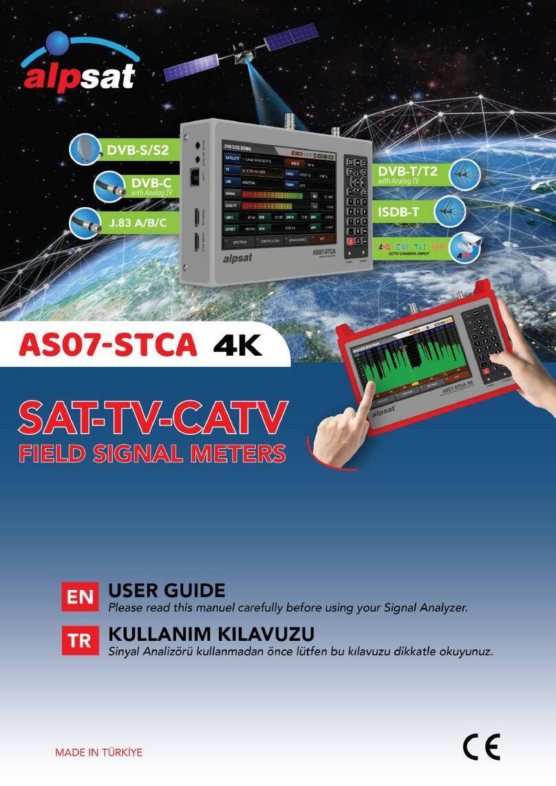
Alpsat AS06-STC & AHD User manual

1

2
ENGLISH USER GUIDE INDEX
SAFETY INSTRUCTIONS …………………………...………………….…
3
TECHNICAL SPECIFICATIONS..………………….……………….…......
4
FRONT VIEW………………………...………………………………………
6
EQUIPMENT INCLUDED WITH THE DEVICE…...……………………...
7
SATTV LEVEL MEASUREMENTS..………………………………………
9
SATELLITE SEARCH……………………………………………….………
10
SATTV SPECTRUM ANALYZER………………………………………….
12
SATTV TP CONTROL………………...…………………………………….
13
SATTV CONSTELLATION..………………………………………………..
14
SATTV MULTI LEVEL CONTROL.…………………………………….….
14
SATTV AUTO PORT SEARCH.…………………………………………...
15
SATTV CHANNEL LIST…………………………………………………….
15
SATELLITE SETTINGS...……………………………………………..........
17
DVB-S/S2 SETTINGS...………………………………………………….....
17
CABLE TV ANALOGUE and DIGITAL INSTRUCTIONS……….….……
18
CABLE TV LEVEL MEASUREMENT...……………………………………
18
CABLE TV SPECTRUM ANALYZER….……………………………….....
20
CABLE TV CONSTELLATION……………………………………………..
21
CABLE TV TILT / LIMIT…..….…………………………………………......
22
CABLE TV SEARCH TABLE…...…………………………………………..
22
CABLE TV CHANNEL LIST….…………...………………………………..
22
CABLE TV SETTINGS.…...…………...……..…...………………………..
23
CABLE TV FREQUENCY PLAN..………………………………..….........
23
TERRESTERIAL TV ANALOGUE and DIGITAL INSTRUCTIONS.……
24
TERRESTERIAL TV LEVEL MEASUREMENT ………………………….
24
TERRESTERIAL TV SPECTRUM ANALYZER….…………………........
26
TERRESTERIAL TV CONSTELLATION……...…………………………..
27
TERRESTERIAL TV TILT / LIMIT…..….………………………………….
28
TERRESTERIAL TV SEARCH TABLE…...……………………………….
28
TERRESTERIAL TV CHANNEL LIST….…………...…………………….
29
TERRESTERIAL TV SETTINGS.…...…………...……..…...…………….
29
TERRESTERIAL TV FREQUENCY PLAN..………………………………
29
AHD / CVBS CCTV AV INPUT…………...………………………………..
30
MAIN SETTINGS…………………………………………………………….
30
ENGLISH

3
SAFETY INSTRUCTIONS:
Issues to be Observed:
Make sure to observe the following instructions in order to prevent yourself and
your device from incurring any harm.
Pull out the charging cable before cleaning your device, and turn it off using the
Power On/Off button, and clean it with a dry cloth.
Do not use accessories or additional attachments that are not recommended by the
manufacturer since it may damage your device or invalidate your device's warranty. Protect
your device from impacts and falls while carrying it, otherwise it might be damaged. Make
sure to carry your device in its bag and do not carry it in boxes such as toolbox and with
equipment which may cause damage on it, otherwise your device's warranty will become
void.
Avoid using your device in outdoors in rainy and snowy weather, in order to protect
it from contact with water. If you detect smoke odor or other odors or unusual sound
coming from the inside of your device, turn it off and consult to technical service.
Charge your device with the recommended charging adapter and car lighter
charger. Inappropriate charging devices will damage the batteries in your device, and may
cause events such as overheating and explosion or it may harm you, and such cases are
under the user's own responsibility. Make sure the charging adapters are supplied with 12
volts 1500mAh (middle center +). Do not leave your device open, as the batteries in
devices which are left open will lose their function in time.
Lighter charger, charging adapter and batteries are outside the scope of warranty since
their life span varies depending on usage. Be careful against short circuits while connecting
your device to LNB, otherwise the LNB and your device might be damaged.
Issues Regarding Service:
Do not attempt to repair your device yourself. Your device will no longer be within
the scope of warranty if you open its cover. Consult your dealer or technical service for all
services regarding the device.
Use the batteries sold or recommended by the manufacturer.

4
TECHNICAL SPECIFICATIONS:
MAIN FUNCTIONS:
DVB S-S2 / T-T2 / C COMBO Signal Analyzer
All in one 45-2150mhz 75 ohm (“F”) Rf input
AHD and CVBS video input for CCTV cameras
3.5” high resolution and high brightness display
MPEG2-4 SD & HD pictures with Program List, Audio Video PIDs all on one screen.
Support AAC supplied, DOLBY
800 MHz processor speed - 8MB Memory
3000mAh 7.4V replaceable Li-Po Battery with up to 4 hours duration
Usb Memory Software upgrade and Frequncy Database update
Pc software for Frequency database update
30 Catv , 30 Terresterial , 150 Sat programmable plan by PC or Local Keyboard.
5000 frequency memory
Numeric Silicone keypad with backlight
Power save timer functions
dBm , dBuV and dBmV levels
Level warnings with speaker
Led Flash Light
Test Voltage levels for end user
Weight only 1 kg with battery
Size 190mm X 110mm X 60mm
Temperature range 0 °C to +50 °C
Humidity Up to 90% non condensing
With silicone case and padded bag.
12Volt 1.5A Charger and Car Lighter Charger
SATELLITE:
DVB S/S2 Measuring SAT: 950 - 2150 Mhz
-80 to 0 dBm power measurment range
BER , MER , C/N digital measurments.
Level Measurement Accuracy 1 dB typ. (2.5 dB max.)
Spectrum Analyzer: Real Time Spectrum with capture
50 , 75 , 150 , 300 , 600 , 1200mhz Spectrum Span
Automatically TP identifies NIT function in spectrum menu
Tp Control : 4 Tp’s Levels of one and two Satellite in one screen
Multi Sat Level Control: Dual Feed LNB 2 satellite’s levels in one screen
Satellite Constellation: Qpsk & 8psk for Sat.
Auto Port Scan: Diseqc 1.0-1.1-Unicable ports search for sat.
150 satellite’s more than 2000 TP Frequency current database
Automatic Signal Quality analysis assistant
HD & SD Sat Tv Video
FEC: DVB-S: 1/2, 2/3, 3/4, 5/6, 7/8 - DVB-S2: 1/2, 2/3, 3/4, 5/6, 8/9, 9/10, 2/5, 3/5
Symbol Rate: 1 to 45MS/s Full automatic selection
Supports DiSEqC 1.x, DiSEqC 2.x and USALS
Unicable 1&2 EN50494/EN50607
Lnb Power Supply : 13V/18V/21V - 500mA
Supports 32 Lnb Type
KA , KU, C , L / R band

5
CABLE TV:
DVB C and Analog Measuring CATV : 45 - 1002 MHz
-90 to 0 dBm power measurment range
BER , MER , C/N digital measurments.
Analog Catv level and V/A ratio 4dB to 26dB
Analog Audio carrier 4,5MHz, 5,5 MHz, 6,0 MHz, 6,5 MHz
Level Measurement Accuracy 1 dB typ. (2.5 dB max.)
Spectrum Analyzer: Real Time Spectrum with capture
15 , 30 , 50 , 100 , 200 , 500 , 1000mhz Spectrum Span
Automatically TP identifies NIT function in spectrum menü
TILT / LIMIT Function for full band
Automaticly scan and prapare search table
Edit Frequency Plan database by Pc or Keypad
Catv Constellation: 16QAM, 32QAM, 64QAM, 128QAM, 256QAM
DVB-C & QAM Annex A/C
Symbol rate: 2 to 6.999MS/s - Automatic selection
6 MHz, 7 MHz, 8 MHz Channel Bandwidth
30 Frequency Plan more than 4000 TP Frequency
Automatic Signal Quality analysis assistant
HD & SD CATV Digital Video
TERRESTERIAL:
DVB T/T2 and Analog Measuring Terr : 45 - 1002 MHz
-90 to 0 dBm power measurment range
BER , MER , C/N digital measurments.
Analog Terresterial level and V/A ratio 4dB to 26dB
Analog Audio carrier 4,5MHz, 5,5 MHz, 6,0 MHz, 6,5 MHz
Level Measurement Accuracy 1 dB typ. (2.5 dB max.)
Spectrum Analyzer: Real Time Spectrum with capture
15 , 30 , 50 , 100 , 200 , 500 , 1000mhz Spectrum Span
Automatically TP identifies NIT function in spectrum menü
TILT / LIMIT Function for full band
Automaticly scan and prapare search table
Edit Frequency Plan database by Pc or Keypad
Terr Constellation: QPSK, 16QAM, 64QAM (DVB-T) 256QAM (DVB-T2)
FEC : DVB-T: 1/2, 2/3, 3/4, 5/6, 7/8 , DVB-T2:1/2, 2/3, 3/4, 5/6, 7/8, 3/5, 4/5
1.7 MHz , 5MHz , 6 MHz, 7 MHz, 8 MHz Channel Bandwidth
30 Frequency Plan more than 4000 TP Frequency
5V / 12V / 20V-250mA antenna power supply
Automatic Signal Quality analysis assistant
HD & SD TERR Digital Video

6
FRONT CONTROL PANEL VIEW
RF & LNB INPUT
AHD/CVBS INPUT
AV OUTPUT
12V CHARGE IN
CHARGE LED
POWER LED
USB MEMORY IN
NUMERIC KEYPAD
EDIT –SPAN –FREQ
POINTER
DIRECTION KEYS
MUTE –SAT LIST
ON-OFF BUTTON
LEVEL –C/N - MOTOR
MENU –SAT SELECT
LED LAMP ON/OFF
AV IN SELECT
TV / RADIO SELECT
ESCAPE FUNCTION
OK & ENTER
LED TORCH LAMP

7
EQUIPMENT INCLUDED WITH THE PRODUCT:
1 piece of Silicone Cover with Shoulder Strap:
The silicone cover with shoulder strap protects your device from
negative external factors such as dust, dirt and fall down. The
protective cover cannot protect against squeezing and heavy
impacts. Your device may become outside the scope of warranty.
1 piece of 220V Charging Device:
With your 12 Volt output electrical charging adapter, you
can ensure your device is kept charged all the time, and
thus use your device in environments where electricity
is not available. Prevent your charging adapter from
squeezing, impacts and overload. Do not open for
repairing or examining.
1 piece of Lighter Charging Device:
With your 12 Volt output lighter charging adapter, you
can ensure your device is kept charged all the time, and
thus use your device in environments where electricity is
not available. You can charge your device while you are
driving your car. Prevent your lighter charging adapter
from squeezing, impacts and overload. Do not open for
repairing or examining.

8
1 piece of A-V Cable:
You can test the external Video and Audio signals with
the AV input of your device. You can also test devices
such as security cameras which require focus and
direction adjustment.
1 piece of F Female Connector:
Use your F-F Female Connector in your device all the time.
With the F-F Female Connector, the Tuner input of your
device will not be affected by factors such as wearing,
tearing and overuse.
1 piece of Carrying Bag:
The Carrying Bag with shoulder strap protects your
device from negative external factors such as dust,
dirt and fall down. You can carry your device with this
bag.

9
SATELLITE MEASUREMENT USER INSTRUCTIONS:
STARTING THE DEVICE:
Press the POWER ON/OFF button and turn your device on. Please choose DVB S/S2 for satellite MENU. On the TV
broadcast screen will the TV/Radio channel list appear with the ENTER button.
SOUND ADJUSTMENT:
While watching any channel, you can change the sound volume with the RIGHT/LEFT buttons or shut it
complete off with the MUTE button.
COLOUR ADJUSTMENT:
While watching any channel, you can change the colour settings of the image when you keep the EDIT button
pressed.
LEVEL INDICATOR:
While watching any channel, you can instantly the signal levels of the watched channel on the screen in real time
when you press on the LEVEL button. Beside this, the colour of the level indicators will turn from grey to green
and red when you lock on any channel.

10
SATELLITE SEARCH MENU:
Call the MAIN MENU to the screen by pressing on the MENU button and select the SATELLITE SEARCH menu by
using the down - up buttons. Select the satellite you want to set your satellite dish or see the signal levels of, the
transponder, the Diseqc type and the LNB type and press on ENTER.
You can see the signal levels on the screen that appears. You can check whether the signal levels have the highest
values or not. By pressing the LEVEL button, you can see the levels on the detailed screen. You can change the
ordered transponders with the RIGHT/LEFT buttons.
After having adjusted the signal level in the best way, you can press on the ENTER button and perform a CHANNEL
SCAN. You can perform the scan processes as SINGLE TP/ALL TP and BLIND SCAN, and then add the detected
channels to the CHANNEL LIST by following the instructions indicated in the figures below.
Thus, the channels are recorded into the memory and added to the end of the CHANNEL LIST.

11
USALS MOTOR SETTING:
Select the DISEQC type as USALS MOTOR in order to use the Diseqc Motors with Usals commands. Go ver to the
USAL SETTINGS menu by holding the EDIT button pressed for 2-3 seconds. Enter the coordinates of the region,
where you will perform the satellite setting and mark the OK box and the SATELLITE DISH will AUTOMATICALLY
go to the position of the satellite, when you then go to the GO box and press on ENTER.
UNICABLE I&II SETTINGS MENU:
You can use this menu for the UNICABLE Multiswitch or Unicable SCR LNB types and conduct the tests after
having performed these settings. First, select the DISEQC type as UNICABLE and go to the PORT section and
keep the EDIT button pressed for 2-3 seconds.
You can adjust on this screen the output IF frequencies according to the Unicable Multiswitch or Unicable SCR
LNB type you will test. Then you can test the signals from the SATELLITE SETTINGS menu.
DISEQC 1.2 MOTOR SETTING MENU:
First select in the DISEQC TYPE section the option Diseqc 1.2 Motor and go to the SATELLITE SETTINGS menu
signal levels by pressing on the ENTER button. Here you can view the signal levels and at the same time manually
rotate with the RIGHT/LEFT buttons your Diseqc 1.2 Motor in EAST/WEST directions. Your battery could be
discharged faster than normal since the DISEQC MOTOR will consume more poser in this menu. Please keep your
charging device available at this scan type.

12
SPECTRUM ANALYSIS MENU:
Press on the MENU button and select the SPECTRUM ANALYSIS box in the MAIN MENU. After having performed
your Satellite, LNB Voltage, Scan Width and Diseq-c setting, select the IF frequency you want and press on the
OK button.
The C/N value will appear, when you press once on the LEVEL button on this screen.
You can record the spectrum levels on the screen into the memory with the CAPTURE RECORD function when you
press on the MENU button on the SPECTRUM ANALYSIS screen and LOAD these from the memory during your
next assembly and perform again an installation with the same settings.
You can change the SPECTRUM SPEED via the SPEED box. But some signal levels might not be shown detailed in
the FAST mode.
You can fit the upper and lower signal levels into the automatic measurements levels screen in the AUTO RANGE
mode.
You change the IF Frequency, BANDWIDTH and LNB VOLTAGE values by pressing on the EDIT button.

13
NIT RECOGNITION FEATURE:
You can find the CHANNEL LIST and the SATELLIRE Position in Uplink automatically by pressing the ENTER button
when you have moved the IF Frequency cursor on a signal in the Spectrum Analysis menu.
NOTE: The satellite name might be indicated wrong due to the information in the NIT data in some cases when
the NIT data in the signals transmitted by the broadcasting institution should be faulty or when the broadcasting
company broadcasts to 2-3 satellites simultaneously.
You can see the channel lists, and record the channels into the memory with the setting performed with the
Universal LNB.
SATELLITE TP CONTROL MENU:
Press on the MENU button and select from the MAIN MENU the option SATELLITE TP CONTROL. The Satellite TP
Control menu allows also the indication of the signal levels of multiple TP frequencies.
SINGLE SATELLITE CONTROL:
Select SINGLE as type and press on ENTER after having performed the necessary SATELLITE settings. As to be
seen on the screen; it possible to visualize the signal levels of 4 different frequencies from 1 satellite on the same
screen. With this, you can control whether the signal levels and antenna setting are correct at all frequencies, or
not.

14
DOUBLE SATELLITE CONTROL:
Select DOUBLE as type and press on ENTER after having performed the necessary SATELLITE settings.
As to be seen on the screen; it possible to visualize the signal levels of 8 different frequencies from 2 satellite on
the same screen. You can test and control the correctness of the Multiswitch and System assembly by visualizing
all frequencies on the same screen.
CONTELLATION MENU:
Press on the ENTER button and select CONSTELLATION in the MAIN MENU. The constellation menu shows the
correctness of the digital I/Q symbol coordinates received at any time in a graphic. With this, you can also check
the correctness of the performed modulation (like QPSK, 8PSK).
Enter the constellation menu, select the satellite and the TP frequency, of which you will check the correctness
and press on the ENTER button after you have performed your settings. In the constellation diagram have the
QPSK signals 4, the 8PSK signals 8 coordinate points. The closer these coordinate points are to each other, the
more increases the correctness.
MULTILEVEL CONTROL MENU:
Press on the MENU button and select MULTILEVEL CONTROL in the MAIN MENU.
In the Multilevel Control Menu are the signal levels of each one frequency from 2 different satellites indicated on
the same screen. With this can Monoblock LNB installations and Multiswitch tests be performed very easily.

15
AUTO PORT SCAN MENU:
Press on the MENU button and select AUTO PORT SCAN in the MAIN MENU. You can see in this menu which
satellite is connected to which Diseq-C port.
Select NONE/NA in cases, where no Diseq-C swich is available and the cable is directly connected to the LNB
Tone Burst Port Scan:
Diseq-C 1.0 Port Scan:
CHANNEL LIST MENU:
You can call the CHANNEL LIST by pressing on the ENTER button in the MAIN MENU while watching any channel.
You can select, cancel and relocate in the Channel List menu the TV and Radio channels one by one or according
to the satellite name.

16
ORDERING BY SATELLITE:
After having entered into the CHANNEL LIST menu, press on the MENU button and select the SATELLITE. In this
case will only the channels of the selected satellite be displayed.
CHANNEL DELETE:
Press on the EDIT button when you are in the CHANNEL LIST menu and select the DELETE box.
Select the channels you want to delete on the screen one by one with the ENTER button and finally press on
EDIT. The channels will be permanently deleted when you check YES to the question “RECORD?” while leaving
all menus.
MOVE CHANNELS:
Press on the EDIT button when you are in the CHANNEL LIST menu and select the RELOCATE box.
Select the channels you want to relocate one by one with the ENTER button and press on the EDIT button when
you are at the position you want to relocate them. The channels will be relocated to the position you wish when
you check YES to the question “RECORD?” while leaving all menus.

17
SATELLITE SETTINGS MENU:
You can fix the Diseq-C and LNB types suitable for the satellites and TP frequencies in the region you provide
services in this menu. With this will the settings be used you have performed in all menus and you will be able to
set faster. (Please always control the correctness of your settings since some menus are using these settings.)
Beside this, you can delete ALL TPs of the satellites and perform a CHANNEL SCAN for these satellites in this
menu.
DVB-S/S2 SETTINGS:
You can perform the valid changes in the DVB S/S2 menus through the SETTINGS MENU. You can change active
reagion fort he Satellite list.
INDICATOR: Shows the power level indicators in dBm, dBuV and dBmV.
LEVEL SETTING: You can calibrate it when you think that the signal measurement indicator is low or high.
AUTO CONVERSION: You can select in the Automatic Satellite and Port Recognition menus the number of the
satellites you want to be controlled.
MEMORY INFORMATION: You can check how much memory is used in the satellite section.

18
ANALOGUE and DIGITAL CABLE TV USER INSTRUCTIONS:
STARTING THE DEVICE:
Press the POWER ON/OFF button and turn your device on. Select the DVB-C box in the STC MAIN MENU; the
TV/Radio channel list will appear on the screen.
LEVEL INDICATOR:
While watching any channel, you can instantly the signal levels of the watched channel on the screen in real time
when you press on the LEVEL button.
LEVEL MEASUREMENT MENU:
Press on the MENU button and go to the CATV MENU screen and start performing the measurement by selecting
the LEVEL MEASUREMENT box. You can perform in the CATV LEVEL MEASUREMENT menu the measurement of
the ANALOGUE and DVB-C QAM digital frequencies in the frequency plan you have selected.
DVB-C / QAM MEASUREMENT:
Select DVB-C in the SYSTEM box in the CATV LEVEL MEASUREMENT menu. Use the RIGHT/LEFT buttons in order
to select the CHANNEL and FREQUENCY you want to measure, or go on FREQUENCY and enter the frequency you
wish and select a bandwidth of 6, 7, 8 MHz for the DVB-C measurement.

19
Go to the measurement screen by pressing on the OK button after you have entered the parameters of the
frequency you want to measure. The orange, thick bar on the right of this screen indicates the signal level visually.
The signal level is indicated in figures below the orange bar. You can see from the green area whether the Orange
Level Performance Bar is within the Max and Min values you will select in the settings menu. And on the left side
of the screen, you can see the frequency parameters and the signal values like MODULATION, BER, MER. A
FAILURE indication will appear in the small box in the right bottom when the signal values are insufficient and an
OK indication when the signal values are appropriate. The Channel names will be indicated in the orange bar,
when the signal levels are appropriate. You can see the names of the channels in the frequency you have
measured by pressing on the LIST button. Note: You can jump fast to the other menus related to the frequency
you have measured with the SPECTRUM, CONSTELLATION and SEARCH boxes at the very bottom. Detailed
information will be provided in the following pages with regards to the Spectrum Analysis and Constellation
features.
SEARCHING A CHANNEL ON THE FREQUENCY AND RECORDING INTO THE CHANNEL LIST:
Go down to the “SEARCH” box in the right bottom section on a frequency you are sure that the signal levels are
appropriate and press on the OK button. You can perform a scan on the CHANNEL SEARCH screen by selecting
the options NON-CODED and ENCODED and both together. The channels you scanned will be found and then the
information screen will appear and you will be asked whether you want the channels to be recorded or not.
ANALOGUE CABLE TV MEASUREMENT:
Select ANALOGUE in the SYSTEM box in the CATV LEVEL MEASUREMENT menu. Use the RIGHT/LEFT buttons in
order to select the CHANNEL and FREQUENCY you want to measure. You can enter the Video Frequency and
Sound Frequency information for the ANALOGUE CATV measurement with the EDIT button by moving on the
boxes.
Go to the measurement screen by pressing on the OK button after you have entered the parameters of the
frequency you want to measure. On this screen you can see the Channel Name, the Video Frequency Strength,
the Sound Frequency, the Sound Frequency Strength and the delta difference between VIDEO/AUDIO in dB
format. And you can accelerate your visual measurement by the signal strength bars on the right side of the
screen changing depending on the level and being orange for the Video Frequency Strength and blue for the
Sound Frequency Strength. You can see from the green area whether the Orange Video Level Performance Bar
and the Blue Sound Level Performance Bar are within the Max and Min values you will select in the settings menu.

20
A FAILURE indication will appear in the small box in the right bottom when the signal values are insufficient and
an OK indication when the signal values are appropriate.
Note: You can jump fast to the other menus related to the frequency you have measured with the SPECTRUM
box at the very bottom. Detailed information will be provided in the following pages with regards to the Spectrum
Analysis features.
SPECTRUM ANALYSER MENU:
Press on the MENU button and go to the CATV MENU screen and start performing a measurement by selecting
the SPECTRUM ANALYSER box. The device will display all ANALOGUE and DIGITAL carrier signals determined to
be within the span (the frequency range) when it is set over to the SPECTRUM ANALYSIS measurement mode.
Please select the ANALOGUE or DIGITAL frequency, the WIDTH (the frequency area), the REFERENCE (upper
measurement point) and the RANGE (the range between the upper and lower measurement points).
The ANALOGUE and digital signals can be displayed in different forms on the spectrum screen depending on the
band widths and the strength levels.
Clicking on the MENU button:
The screen above will appear when we click on the MENU button while you are in the Spectrum screen.
AUTO RANGE: Determines the top and lowest levels of the signal levels and establishes the screen indicator range
according to this.
LINE/FILLED: Shows the spectrum image in lines or filled.
SPECTRUM CAPTURE: Records the spectrum image on the screen and you can call this lined visualization at a
later time and compare it with the last measurement you have performed.
SAVE TO USB: You can record the image data on the spectrum screen on your USB memory card.
Table of contents
Other Alpsat Measuring Instrument manuals
Popular Measuring Instrument manuals by other brands

Actility
Actility Click & Go Extreme Cold Quick starter guide

Futek
Futek IHH500 Setup guide

Rohde & Schwarz
Rohde & Schwarz ZVT Series Getting started

PCB Piezotronics
PCB Piezotronics ICP J353B18 Installation and operating manual

Anritsu
Anritsu MU196020A PAM4 PPG Operation manual

Humboldt
Humboldt GeoGauge H-4140 Calibration guide