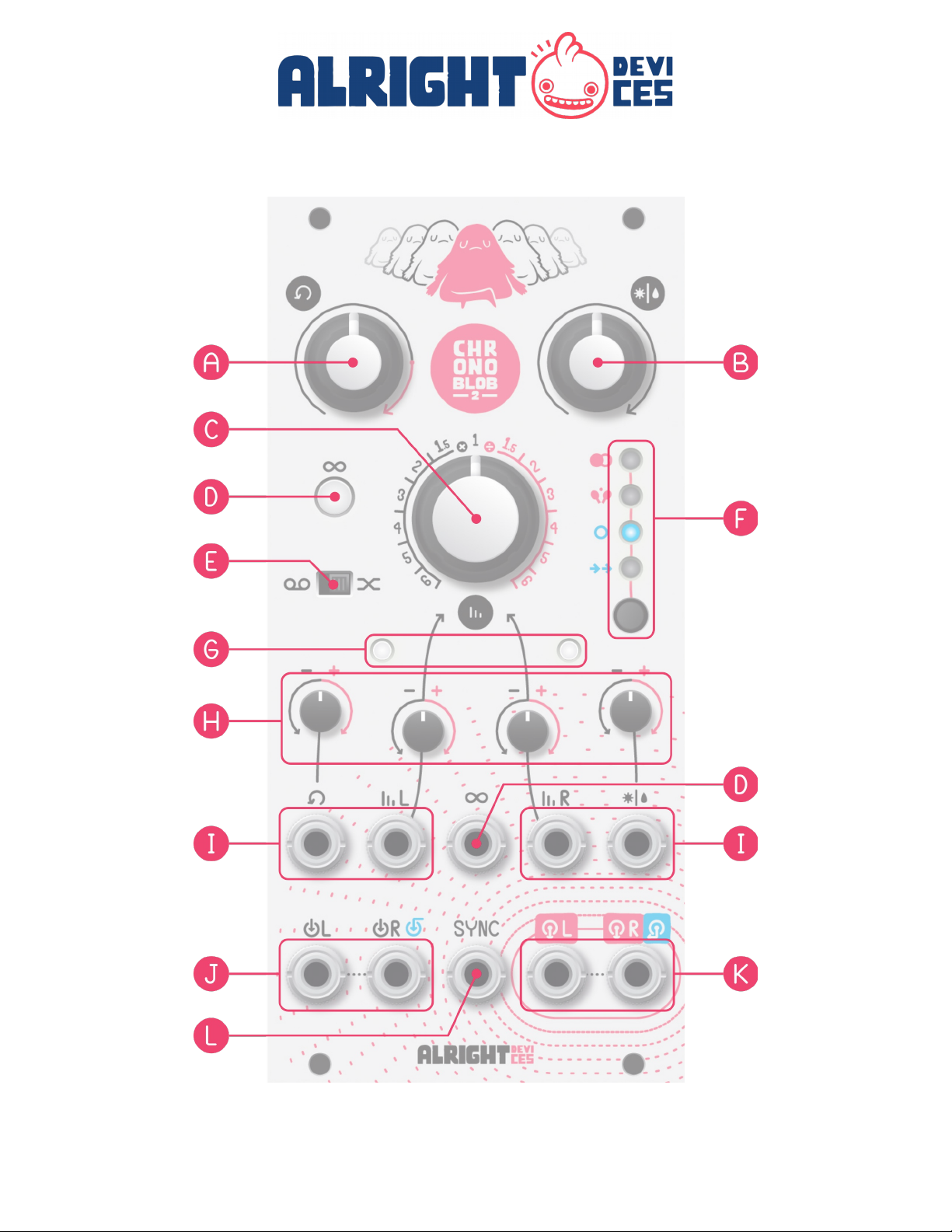
G. Status I dicators
Each delay has a corresponding status LED, which links white at the
delay rate and glows red when the input is overloaded (over 20Vpp). In
DUAL and PING-PONG modes, they correspond to the left and right
delays. In CASCADE mode, the left indicator corresponds to the outer
delay; the right to the inner. In SINGLE mode, the indicators ehave
identically.
H. CV atte uverters
These kno s control how strongly the CV inputs affect the feed ack
amount, delay time, and dry/wet mix. If an attenuverter is in its center
position, the corresponding CV will have no effect. As it is turned to
the left, the CV has an increasing inverted effect (positive voltage
reduces feed ack, shortens delay time, or makes the mix more dry).
Turned to the right, the CV has a noninverted effect (positive voltage
increases feed ack, lengthens delay time, or makes the mix more wet).
I. CV i puts
Connect CV signals to these inputs to modulate feed ack amount, delay
time, and dry/wet mix. You can scale the incoming CV signals y using
the corresponding attenuverter.
Note: When nothing is connected to the left TIME CV input, it is
normally connected to +5V. Similarly, when nothing is connected to the
right TIME CV input, it is normally connected to the same source as the
left (either an external CV signal or the aforementioned +5V). This
allows you to use the attenuverters as offsets controlling the lengths
of two delays separately without using external CV. In SINGLE delay
mode, the right CV input has no effect.
9