9
MAINTENANCE CAUSE INJURY SHOULD YOU ATTEMPT TO DISASSEMBLE
WHILE PRESSURIZED.
Purge Muffler
At high pressures a clogged muffler could result in a high backpressure and could result in mechanical failure or
personal injury. For this reason the purge muffler must be periodically checked for any restrictive debris. If pres-
sure is observed on the offline tower replace muffler immediately.TO AVOID INJURY, DEPRESSURIZE DRY-
ERRFORMI
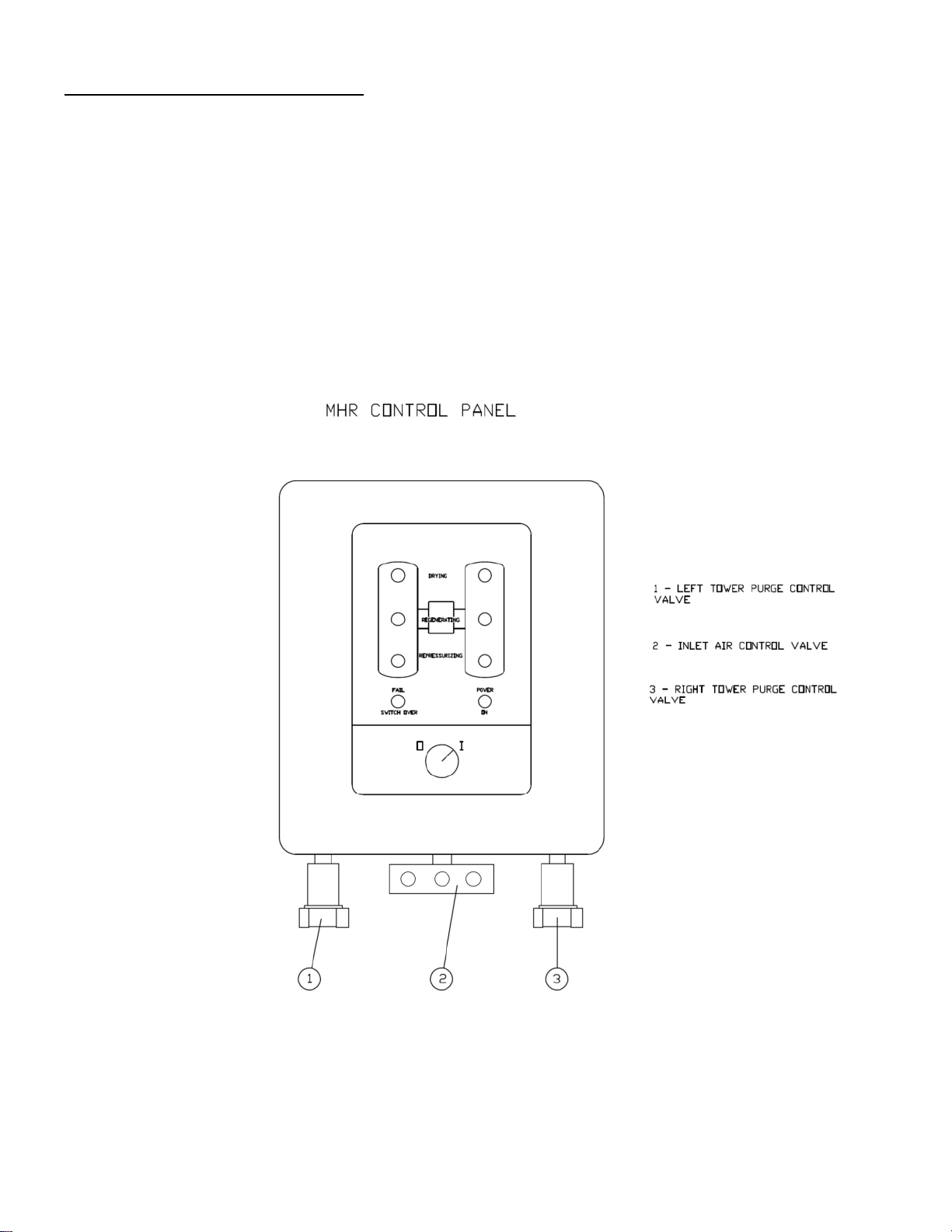
Purge Valves
Should either of the normally closed purge valves fail to operate check the following:
1. Check air signal to valve.
2. If air signal is present; disassemble, clean and replace diaphragm and seals.
3. If no air signal is present; see solenoid valve information in Maintenance Section.
Inlet Valves
Should either of the normally open inlet valves fail to operate check the following:
1. Check air signal to valve.
2. If air signal is present; disassemble, clean and replace diaphragm and seals.
3. If no air signal is present; see solenoid valve information in Maintenance Section.
Outlet and Purge Check Valves
NOTE: Signs of a faulty outlet and/or purge check valve include;
Failure to Depressurize Alarm
System air is being drained and compressor is running at below normal efficiency.
Periodically check the outlet and purge check valves for an absolute seal. Procedure:
Close purge adjustment valve. Verify offline tower pressure is 0 PSIG.
Check offline purge muffler for airflow. No airflow should be present.
If no airflow is present, the outlet and purge check valve have a positive seal. Repeat procedure next
cycle to check opposite outlet and purge check valves
If airflow is present, the outlet and/or purge check valves do not have a positive seal. Clean and/or re-
place corresponding check valves. See air flow diagram for corresponding check valves.
Pilot Air-Filter (Located at Outlet)
For maximum filtration efficiency, service the element 2x per year.
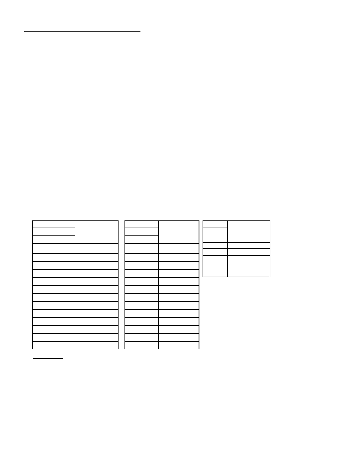
PREVENTATIVE MAINTENANCE SCHEDULE
Daily
Check and record inlet pressure, temperature and flow.
Verify that it is within specifications.
Check tower pressure gauge readings within operating tol-
erance.
Check tower pressure gauges for proper dryer cycling.
Verify that pressure in purging tower is 5 PSIG or less.
Verify that prefilters and off-line differential pressure is
within operating limits.
Semi-Annually
Check outlet dew point.
Blow down relief valves.
Monthly
Check your operating conditions: inlet flow, inlet pressure,
and inlet temperature.
Check prefilters and after filters.
Check dryer cycle and sequence of operations, (i.e. drying and
regenerating).
Annually
Check desiccant and replace if necessary.
Inspect and clean pilot operated valves and re-
place packing as necessary.
Inspect and clean solenoid valves, check
valves and purge lines.
Test electrical components, replace as neces-
sary.
Quarterly (3 Months)
Check pilot air filter element and clean.
Replace prefilter and afterfilter elements.
3-Years
Replace desiccant (if necessary)