Altman Lighting Product Warranty 3
AP-150 RGBW Par LED Luminaire Installation & User’s Manual
TABLE OF CONTENTS
Have a question regarding this manual? ............................................................ Inside Front Cover
Our Commitment ................................................................................................ Inside Front Cover
Important Information
Product Safety Notices ................................................................................................................... 1
Warnings......................................................................................................................................... 1
FCC NOTICE ........................................................................................................................................ 1
Altman Lighting Product Warranty......................................................................................................... 2
Warranty Term................................................................................................................................ 2
Warranty Service ............................................................................................................................ 2
Table Of Contents
Preface
About this Manual ................................................................................................................................. 5
Accessories........................................................................................................................................... 5
AP-150-RGBW Accessories ........................................................................................................... 5
AP-150 RGBW Par LED Luminaire Overview
AP-150 RGBW Par LED Luminaire Features ....................................................................................... 6
Installation and Set Up
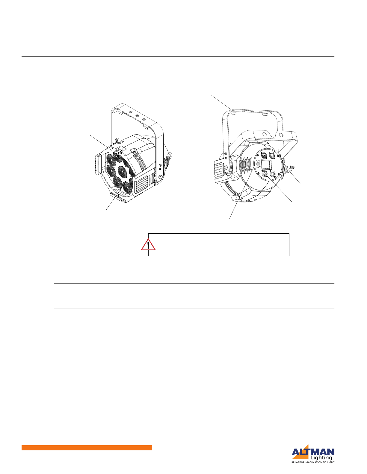
Overview ............................................................................................................................................... 7
Power Connection Warnings................................................................................................................. 7
Connecting Power................................................................................................................................. 7
Daisy-Chaining Units ...................................................................................................................... 8
Menu System
Menu Overview ..................................................................................................................................... 9
Menu System Features ......................................................................................................................... 9
Status LED Indicators..................................................................................................................... 9
LCD Display.................................................................................................................................. 10
Setting DMX Address from the Home Screen .............................................................................. 11
Main Menu .......................................................................................................................................... 12
DMX Menu.................................................................................................................................... 12
STATUS Menu.............................................................................................................................. 14
MANUAL Menu............................................................................................................................. 15
ZOOM CONTROL Menu .............................................................................................................. 17
Fan Control................................................................................................................................... 18
GENERAL SETTINGS Menu........................................................................................................ 19
Security......................................................................................................................................... 19
General Menu Options.................................................................................................................. 20
Factory Default ............................................................................................................................. 21
Connecting to the DMX512 Network
DMX - XLR Connectors ................................................................................................................ 22
DMX Mapping and Control
DMX Mode Options............................................................................................................................. 23
RGBW 16 Bit Direct Mode (15 Channels) .................................................................................... 23
RGBW 8 Bit Direct Mode (10 Channels) ...................................................................................... 23
HSIC Mode (10 Channels)............................................................................................................ 23
RGB Mode (8 Channels) .............................................................................................................. 24
DMX Maps .......................................................................................................................................... 24
RGBW 16 Bit Direct Mode Map .................................................................................................... 24