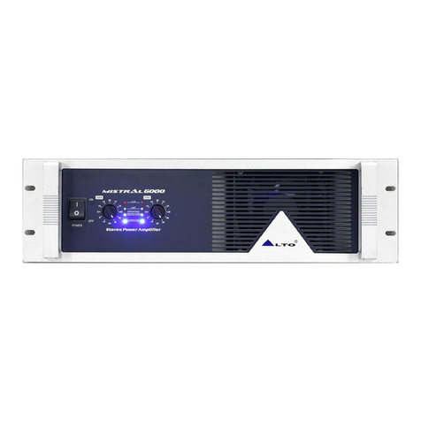
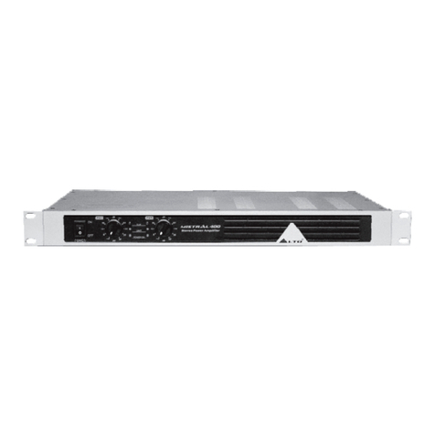
Alto MISTRAL 900 User manual

Service
MODEL: MISTRAL900/1500
www.altoproaudio.com
Version2.0

1
CONTENTS
1. Introduction..………………………………………………………….………………..…2
2. Specification.…………………………………………………………….……….……….3
3. Schematic Diagram…………….…………………….……….….…………………..…..4
4. PCB Layout........……………….…………….………...…….………………….…….…11
5. Test Procedure..……………….…………….………...…….………………….……….15
6. Exploded Views & Mechanical Parts List…….………………………….……....….16
7. BOM....................................................................…………………….…………..…....19

2
1. Introduction
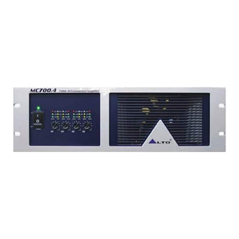
ALTO MISTRAL amplifiers are series of innovative design power amplifiers. This series work under high
stability with great power supply in just 2-rack spaces. Airflow is from back to front panel to keep in a nice air
circulation inside the Rack. The automatic fan, which affects the temperature of machine includes various
kinds of speed, therefore, this low-noise fan makes a good result in cooling the heat from machines. MISTRAL
amplifiers include 2 independent channels with separate protection system and power supply. The
independent protection system avoids opening circuit, short, wrong loading or over-heating. The special-
designed protective system applies automatically restarting functions upon the default status and then goes
back to normal.All electronic inputs equip standard power connectors.And all inputs are electronic balanced,
with hi-quality transformer, MISTRAL amplifiers provide an outstanding performance in any conditions.
.Innovative design and high stability power amplifiers.
.Fan-cooledAB class high power amplifier in 19”rack, 2Usize
.Rugged amplifiers in a strong, compact chassis.
.2 independent channels with separate protection system and power supply
.Smart-designed protection system for auto re-operation after fault.
.Auto-adjusting speed fan.
.4LEDs for operation/protection, limit, power on and clip
.High-current toroidal transformer designed for high power at 2Ohms with low noise.
.Independent DC and thermal overload protection on each channel.
.IEC standard power connectors.
.Binding post and NEUTRIK® SPEAKON outputs power connectors.
.Balanced XLR inputs/ parallel outputs.
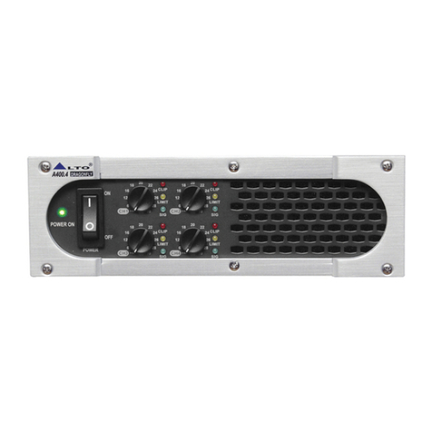
3
2.Specification
MISTRAL900 MISTRAL1500
Output Power
20Hz~20KHz @0.1% THD, SCD MODE
8 ohms per channel (EIAJ) 190W 300W
4 ohms per channel (EIAJ) 300W 500W
BRIDGE MONO MODE
8 ohms , 1KHz, 0.1%THD 1400W 2000W
Distortion (SMPTE-IM) <0.05%
Frequency Response 20Hz-20kHz +/- 0.1dB, -3 dB points: 10Hz-60kHz
Damping Factor, 1 kHz and below >300 at 8 ohms
Signal to Noise, 20 Hz-20 kHz 102 dB
VOLTAGE GAIN 40x (32dB)
Input Sensitivity @ 4 ohms 1Vrms
Input Clipping 10 Vrms (+22 dB)
Input Impedance 10 k ohms unbalanced, 20 k ohms balanced 56(36dB)
Controls FRONT:AC SWITCH, CH1 & CH2 GAIN KNOBS
REAR: LIMITER, BRIDGE SELECTOR.
Indicators (1 per channel)
Power-On: Blue LED
Operation/Protection : Dual Color (Green/Red LED)
Limit : Red LED
Clip : Red LED
Connectors, each channel Input:Active balanced XLR
Parallel Output : XLR
Output: NEUTRIK Speakon and Binding posts
Cooling Continuously variable-speed fan, rear-to-front air flow
Load Protection On/off muting, DC-fault load grounding relay. Internal fault fuses.
Power Requirements 200-240(100-120)Vac 50-60Hz
Dimensions 15.9" (40 cm) deep (rack mounting to rear support ears)
19" (48.3 cm) rack mounting, 3.5" (8.9 cm) tall (2 rack spaces)

1 2 3 4 5 6 78
A
B
C
D
8
7654321
D
C
B
A
+1
G
2
C1_16
4700uF/80V
12
R1_13
22R 1W
12
R1_19
0.1R 3W
A2
K
1
D1_6
1N4148
+73V_A
A
2K1
D1_15
1N4004
GND1
2xMJL21193
B
CE
Q1_1
MJE15030
1 2
R1_21
470R 3W
1 2
C1_13
22nF/100V poly
1 2
C1_11
3.3nF/50 cer
1 2
C1_12
3.3nF/50 cer
12
R1_17
4R7 1W
12
R1_18
4R7 1W
GND1
A2
K
1D1_19
1N4148
EC
B
Q1_2
MJE15031
A
2K1
D1_10
1N4148
B
CE
Q1_4
1 2
R1_14
22R 1W
1 2
R1_20
0.1R 3W
GND1
-73V_A
A
2K1
D1_17
1N4004
A2
K
1
D1_11
1N4937
A2
K
1
D1_12
1N4937
1 2
C1_9
2.2nF/50 cer
12
C1_10
22nF/50 cer
A
2K1
D1_13
ZD5V6 1/2W
12
R1_9
820R
12
R1_11
1K5 2W
12
R1_10
820R
1 2
R1_12
1K5 2W
A
2K1
D1_14
ZD5V6 1/2W
A
2K1
D1_7
1N4148
Vic+
A
2K1
D1_3
ZD15V1.3W
+1
G
2
C1_8
220uF/25V
GND1
12
R1_32
100R
GND1
Vic-
1 2
C1_5
56pF/50 cer
1 2
R1_3
10K
1 2
C1_7
27pF/50 cer
1 2
R1_6
12K SPEAKERS BUS
12
R1_5
330R
12
C1_6
47uF/16NP
GND1
12
R1_30
4K7
12
R1_31
4K7
GND1
CH1 GAIN
+
1G2
C1_27
47uF/25V
A
2K1
D1_8
ZD15V1.3W
+1
G
2
C1_4
220uF/25V
GND1
1 2
C1_25
100pF/50 cer
+
1G2
C1_26
47uF/25V
12
C1_3
100pF/50 cer
+
1G2
C1_23
10uF/50V
GND1
+
1G2
C1_24
10uF/50V
1 2
R1_8
NTC 50R
1
1
22
33
R1_16
TRIMMER 100R
3
21
U1_1A
NJM4580L
5
67
U1_1B
NJM4580L
84
U1_1C
NJM4580L
Vic+
Vic-
B
EC
Q1_3
11
22
33
R1_29
3P-2.5
MIS9-CH1.Sch
Titel
Size
File:
Date:
Drawn By:
Sheet
RevisionModel No:
16-Mar-2004
C.C.LIN
ALTO MISTRAL1500-CH1 DRIVE
32of
MISTRAL1500 VER040302
A2
3
21
U2A
NJM4580L
1 2
R1_42
4K7 1/8W
1 2
R1_41
4K7 1/8W
1
2
3
4
D1_9
W2 - 0 4
GND1
1 2
R1_25
47R
44
1
1
2
233
U1_2
VTL5C2
GND1
(FTR VT90N1 VACTEC+)
GND1
CH1 INSERT OUT
CH1 INSERT IN
1
122
3
344
5
566
7
788
9
910 10
11
11 12 12
13
13 14 14
J4
HEADER 7X2
GND1 GND1
1 2
L1_1
2uH 10A
1 2
R1_26
5R6 2W
12
R1_22
10R 3W
12
C1_2
100nF/250V poly
GND1
CH1 OUTPUT
1+
1-
GND1
TO
SPEAKON PCB
12 R1_36
120K
C1_1
47uF/100V
A
2K1
D1_2
1N4004
12 R1_39
PTC 65R
CH1 PHOTO COUPLER
-15V
+15V
GND1
12
R1_37
12K
(1.5A 200V)
(1.5A 200V)
+1
G
2
C1_15
4700uF/80V
12
R1_7
330R
12
R1_4
330R
11A
6A
6A
12 C1_14
3.3nF/100 poly
1 2
R1_15
150R
0.2A
0.2A
84
U2C
NJM4580L
+15V
-15V
12
D1_18
3mm RED LED
CH1_LIM_SW1
CH1_LIM_SW2
12
D1_21
3mm YELLOW LED
1
12
2J1_6
CON2
1 2
R1_27
10K
1 2
R1_1
10K
1 2
R1_2
10K
12
R1_28
10K
CH1 IN+
CH1 IN-
CH1 IN+
CH1 IN-
CH2 IN+
CH2 IN-
CH1 BRIDGE SWITCH CH2 BRIDGE
CH1_LIM_SW1
CH1_LIM_SW2
CH2_LIM_SW1
CH2_LIM_SW2
CH1 BRIDGE S WITCH
Pout=418W RMS @ 4 Ohm
12
D1_16
3mm GREEN LED
Vic-
Vic+
12
R1_33
3K3 1/2W
OPERATING LED
OUTPUT_1 OUTPUT1
1 2
F1_1
5A
1 2
F1_2
5A
OUTPUT_1
12
R1_34
47K
12
R1_38
10K
100R
10K
A
2K1
D1_5
ZD15V1.3W
1 2
D1_4
5mm RED LED
GND1
GND1
+73V_A
-73V_A
1 2
R1_35
100K
1 2
R1_40
6K8
B
CE
Q1_6
MPSA42
B
EC
Q1_5
MPSA92
Vic+
Vic-
GND1
CLIP
1
1
2
2
3
3
J1_4
CN-PCB 6.3
1
1
2
2
3
3
J1_5
CN-PCB 6.3
1
2
3
4
D1_20
W2 - 0 4
11
22
33
J1_7
CN-PCB 6.3
11
22
33
J1_8
CN-PCB 6.3
11
22
33
J1_9
CN-PCB 6.3
11
22
33
J1_10
CN-PCB 6.3
V+
V-
AC1
GND
1
2
J1_11
CON2
1
2
J2_11
CON2
GND1
CH1 IN+
CH2 IN+
for PBM8

1 2 3 4 5 6 78
A
B
C
D
8
7654321
D
C
B
A
+1
G
2
C2_16
4700uF/80V
12
R2_13
22R 1W
12
R2_19
0.1R 3W
A2
K
1
D2_6
1N4148
+73V_B
A
2K1
D2_15
1N4004
GND1
2xMJL21193
B
CE
Q2_1
MJE15030
1 2
R2_21
470R 3W
1 2
C2_13
22nF/100V poly
1 2
C2_11
3.3nF/50 cer
1 2
C2_12
3.3nF/50 cer
12
R2_17
4R7 1W
12
R2_18
4R7 1W
GND1
A2
K
1D2_19
1N4148
EC
B
Q2_2
MJE15031
A
2K1
D2_10
1N4148
B
CE
Q2_4
1 2
R2_14
22R 1W
1 2
R2_20
0.1R 3W
GND1
-73V_B
A
2K1
D2_17
1N4004
A2
K
1
D2_11
1N4937
A2
K
1
D2_12
1N4937
1 2
C2_9
2.2nF/50 cer
12
C2_10
22nF/50 cer
A
2K1
D2_13
ZD5V6 1/2W
12
R2_9
820R
12
R2_11
1K5 2W
12
R2_10
820R
1 2
R2_12
1K5 2W
A
2K1
D2_14
ZD5V6 1/2W
A
2K1
D2_7
1N4148
Vic2+
A
2K1
D2_3
ZD15V1.3W
+1
G
2
C2_8
220uF/25V
GND1
1
2
3
4
D2_20
W2 - 0 4
12
R2_32
100R
GND1
Vic2-
1 2
C2_5
56pF/50 cer
1 2
R2_3
10K
1 2
C2_7
27pF/50 cer
1 2
R2_6
12K SPEAKERS BUS
12
R2_5
330R
12
C2_6
47uF/16NP
GND1
12
R2_30
4K7
12
R2_31
4K7
GND1
CH1 GAIN
+
1G2
C2_27
47uF/25V
A
2K1
D2_8
ZD15V1.3W
+1
G
2
C2_4
220uF/25V
GND1
1 2
C2_25
100pF/50 cer
+
1G2
C2_26
47uF/25V
12
C2_3
100pF/50 cer
+
1G2
C2_23
10uF/50V
GND1
+
1G2
C2_24
10uF/50V
1 2
R2_8
NTC 50R
1
1
22
33
R2_16
TRIMMER 100R
3
21
U2_1A
NJM4580L
5
67
U2_1B
NJM4580L
B
EC
Q2_3
11
22
33
R2_29
3P-2.5
MIS9-CH2.Sch
Titel
Size
File:
Date:
Drawn By:
Sheet
RevisionModel No:
16-Mar-2004
C.C.LIN
ALTO MISTRAL1500-CH1 DRIVE
33of
MISTRAL1500 VER040302
A2
5
67
U2B
NJM4580L
1 2
R2_42
4K7 1/8W
1 2
R2_41
4K7 1/8W
1
2
3
4
D2_9
W2 - 0 4
GND1
1 2
R2_25
47R
44
1
1
2
233
U2_2
VTL5C2
GND1
(FTR VT90N1 VACTEC+)
GND1
CH2 INSERT OUT
CH2 INSERT IN
12 L2_1
2uH 10A
1 2
R2_26
5R6 2W
12
R2_22
10R 3W
12
C2_2
100nF/250V poly
GND1
CH1 OUTPUT
1+
1-
GND1
TO
SPEAKON PCB
12 R2_36
120K
+1
G
2
C2_1
47uF/100V
A
2K1
D2_2
1N4004
12 R2_39
PTC 65R
CH1 PHOTO COUPLER
-15V
+15V
GND1 (1.5A 200V)
(1.5A 200V)
+1
G
2
C2_15
4700uF/80V
12
R2_7
330R
12
R2_4
330R
11A
6A
6A
12 C2_14
3.3nF/100 poly
1 2
R2_15
150R
0.2A
0.2A
12
D2_18
3mm RED LED
CH2_LIM_SW1
CH2_LIM_SW2
12
D2_21
3mm YELLOW LED
1
12
2J2_6
CON2
1 2
R2_27
10K
1 2
R2_1
10K
1 2
R2_2
10K
12
R2_28
10K
CH2 IN+
CH2 IN-
CH2 BRIDGE
Pout=418W RMS @ 4 Ohm
12
D2_16
3mm GREEN LED
Vic2-
Vic2+
12
R2_33
3K3 1/2W
OPERATING LED
OUTPUT_2 OUTPUT2
1 2
F2_1
5A
1 2
F2_2
5A
OUTPUT_2
12
R2_34
47K
12
R2_38
10K
100R
10K
A
2K1
D2_5
ZD15V1.3W
1 2
D2_4
5mm RED LED
GND1
GND1
+73V_B
-73V_B
1 2
R2_35
100K
1 2
R2_40
6K8
B
CE
Q2_6
MPSA42
B
EC
Q2_5
MPSA92
Vic2+
Vic2-
GND1
CLIP
84
U2_1C
NJM4580L
Vic2+
Vic2-
1
1
2
2
3
3
J2_4
CN-PCB 6.3
1
1
2
2
3
3
J2_5
CN-PCB 6.3
11
22
33
J2_7
CN-PCB 6.3
11
22
33
J2_8
CN-PCB 6.3
11
22
33
J2_9
CN-PCB 6.3
11
22
33
J2_10
CN-PCB 6.3
V+
V-
AC1
GND

1 2 3 4 5 6 78
A
B
C
D
8
7654321
D
C
B
A
+1
G
2
C1_16
4700uF/80V
12
R1_13
22R 1W
12
R1_19
0.1R 3W
12
R1_23
0.1R 3W
B
EC
Q1_7
A2
K
1
D1_6
1N4148
+73V_A
A
2K1
D1_15
1N4004
GND1
2xMJL21193
B
CE
Q1_1
MJE15030
1 2
R1_21
470R 3W
1 2
C1_13
22nF/100V poly
1 2
C1_11
3.3nF/50 cer
1 2
C1_12
3.3nF/50 cer
12
R1_17
4R7 1W
12
R1_18
4R7 1W
GND1
A2
K
1D1_19
1N4148
EC
B
Q1_2
MJE15031
A
2K1
D1_10
1N4148
B
CE
Q1_4B
CE
Q1_8
1 2
R1_14
22R 1W
1 2
R1_20
0.1R 3W
1 2
R1_24
0.1R 3W
GND1
-73V_A
A
2K1
D1_17
1N4004
A2
K
1
D1_11
1N4937
A2
K
1
D1_12
1N4937
1 2
C1_9
2.2nF/50 cer
12
C1_10
22nF/50 cer
A
2K1
D1_13
ZD5V6 1/2W
12
R1_9
820R
12
R1_11
2K2 2W
12
R1_10
820R
1 2
R1_12
2K2 2W
A
2K1
D1_14
ZD5V6 1/2W
A
2K1
D1_7
1N4148
Vic+
A
2K1
D1_3
ZD15V1.3W
+1
G
2
C1_8
220uF/25V
GND1
12
R1_32
100R
GND1
Vic-
1 2
C1_5
56pF/50 cer
1 2
R1_3
10K
1 2
C1_7
27pF/50 cer
1 2
R1_6
12K SPEAKERS BUS
12
R1_5
330R
12
C1_6
47uF/16NP
GND1
12
R1_30
4K7
12
R1_31
4K7
GND1
CH1 GAIN
+
1G2
C1_27
47uF/25V
A
2K1
D1_8
ZD15V1.3W
+1
G
2
C1_4
220uF/25V
GND1
1 2
C1_25
100pF/50 cer
+
1G2
C1_26
47uF/25V
12
C1_3
100pF/50 cer
+
1G2
C1_23
10uF/50V
GND1
+
1G2
C1_24
10uF/50V
1 2
R1_8
NTC 50R
1
1
22
33
R1_16
TRIMMER 100R
3
21
U1_1A
NJM4580L
5
67
U1_1B
NJM4580L
84
U1_1C
NJM4580L
Vic+
Vic-
B
EC
Q1_3
11
22
33
R1_29
3P-2.5
MIS15-CH1.Sch
Titel
Size
File:
Date:
Drawn By:
Sheet
RevisionModel No:
2-Mar-2004
C.C.LIN
ALTO MISTRAL1500-CH1 DRIVE
32of
MISTRAL1500 VER040302
A2
3
21
U2A
NJM4580L
1 2
R1_42
4K7 1/8W
1 2
R1_41
4K7 1/8W
1
2
3
4
D1_9
W2 - 0 4
GND1
1 2
R1_25
47R
44
1
1
2
233
U1_2
VTL5C2
GND1
(FTR VT90N1 VACTEC+)
GND1
CH1 INSERT OUT
CH1 INSERT IN
1
122
3
344
5
566
7
788
9
910 10
11
11 12 12
13
13 14 14
J4
HEADER 7X2
GND1 GND1
1 2
L1_1
2uH 10A
1 2
R1_26
5R6 2W
12
R1_22
10R 3W
12
C1_2
100nF/250V poly
GND1
CH1 OUTPUT
1+
1-
GND1
TO
SPEAKON PCB
12 R1_36
120K
C1_1
47uF/100V
A
2K1
D1_2
1N4004
12 R1_39
PTC 65R
CH1 PHOTO COUPLER
-15V
+15V
GND1
12
R1_37
12K
(1.5A 200V)
(1.5A 200V)
+1
G
2
C1_15
4700uF/80V
12
R1_7
330R
12
R1_4
330R
11A
6A
6A
12 C1_14
3.3nF/100 poly
1 2
R1_15
150R
0.2A
0.2A
84
U2C
NJM4580L
+15V
-15V
12
D1_18
3mm RED LED
CH1_LIM_SW1
CH1_LIM_SW2
12
D1_21
3mm YELLOW LED
1
12
2J1_6
CON2
1 2
R1_27
10K
1 2
R1_1
10K
1 2
R1_2
10K
12
R1_28
10K
CH1 IN+
CH1 IN-
CH1 IN+
CH1 IN-
CH2 IN+
CH2 IN-
CH1 BRIDGE SWITCH CH2 BRIDGE
CH1_LIM_SW1
CH1_LIM_SW2
CH2_LIM_SW1
CH2_LIM_SW2
CH1 BRIDGE SW ITCH
Pout=418W RMS @ 4 Ohm
12
D1_16
3mm GREEN LED
Vic-
Vic+
12
R1_33
3K3 1/2W
OPERATING LED
OUTPUT_1 OUTPUT1
1 2
F1_1
5A
1 2
F1_2
5A
OUTPUT_1
12
R1_34
47K
12
R1_38
10K
100R
10K
A
2K1
D1_5
ZD15V1.3W
1 2
D1_4
5mm RED LED
GND1
GND1
+73V_A
-73V_A
1 2
R1_35
100K
1 2
R1_40
6K8
B
CE
Q1_6
MPSA42
B
EC
Q1_5
MPSA92
Vic+
Vic-
GND1
CLIP
1
1
2
2
3
3
J1_4
CN-PCB 6.3
1
1
2
2
3
3
J1_5
CN-PCB 6.3
1
2
3
4
D1_20
W2 - 0 4
11
22
33
J1_7
CN-PCB 6.3
11
22
33
J1_8
CN-PCB 6.3
11
22
33
J1_9
CN-PCB 6.3
11
22
33
J1_10
CN-PCB 6.3
V+
V-
AC1
GND

1 2 3 4 5 6 78
A
B
C
D
8
7654321
D
C
B
A
+1
G
2
C2_16
4700uF/80V
12
R2_13
22R 1W
12
R2_19
0.1R 3W
12
R2_23
0.1R 3W
B
EC
Q2_7
A2
K
1
D2_6
1N4148
+73V_B
A
2K1
D2_15
1N4004
GND1
2xMJL21193
B
CE
Q2_1
MJE15030
1 2
R2_21
470R 3W
1 2
C2_13
22nF/100V poly
1 2
C2_11
3.3nF/50 cer
1 2
C2_12
3.3nF/50 cer
12
R2_17
4R7 1W
12
R2_18
4R7 1W
GND1
A2
K
1D2_19
1N4148
EC
B
Q2_2
MJE15031
A
2K1
D2_10
1N4148
B
CE
Q2_4B
CE
Q2_8
1 2
R2_14
22R 1W
1 2
R2_20
0.1R 3W
1 2
R2_24
0.1R 3W
GND1
-73V_B
A
2K1
D2_17
1N4004
A2
K
1
D2_11
1N4937
A2
K
1
D2_12
1N4937
1 2
C2_9
2.2nF/50 cer
12
C2_10
22nF/50 cer
A
2K1
D2_13
ZD5V6 1/2W
12
R2_9
820R
12
R2_11
2K2 2W
12
R2_10
820R
1 2
R2_12
2K2 2W
A
2K1
D2_14
ZD5V6 1/2W
A
2K1
D2_7
1N4148
Vic2+
A
2K1
D2_3
ZD15V1.3W
+1
G
2
C2_8
220uF/25V
GND1
1
2
3
4
D2_20
W2 - 0 4
12
R2_32
100R
GND1
Vic2-
1 2
C2_5
56pF/50 cer
1 2
R2_3
10K
1 2
C2_7
27pF/50 cer
1 2
R2_6
12K SPEAKERS BUS
12
R2_5
330R
12
C2_6
47uF/16NP
GND1
12
R2_30
4K7
12
R2_31
4K7
GND1
CH1 GAIN
+
1G2
C2_27
47uF/25V
A
2K1
D2_8
ZD15V1.3W
+1
G
2
C2_4
220uF/25V
GND1
1 2
C2_25
100pF/50 cer
+
1G2
C2_26
47uF/25V
12
C2_3
100pF/50 cer
+
1G2
C2_23
10uF/50V
GND1
+
1G2
C2_24
10uF/50V
1 2
R2_8
NTC 50R
1
1
22
33
R2_16
TRIMMER 100R
3
21
U2_1A
NJM4580L
5
67
U2_1B
NJM4580L
B
EC
Q2_3
11
22
33
R2_29
3P-2.5
MIS15-CH2.Sch
Titel
Size
File:
Date:
Drawn By:
Sheet
RevisionModel No:
2-Mar-2004
C.C.LIN
ALTO MISTRAL1500-CH1 DRIVE
33of
MISTRAL1500 VER040302
A2
5
67
U2B
NJM4580L
1 2
R2_42
4K7 1/8W
1 2
R2_41
4K7 1/8W
1
2
3
4
D2_9
W2 - 0 4
GND1
1 2
R2_25
47R
44
1
1
2
233
U2_2
VTL5C2
GND1
(FTR VT90N1 VACTEC+)
GND1
CH2 INSERT OUT
CH2 INSERT IN
12 L2_1
2uH 10A
1 2
R2_26
5R6 2W
12
R2_22
10R 3W
12
C2_2
100nF/250V poly
GND1
CH1 OUTPUT
1+
1-
GND1
TO
SPEAKON PCB
12 R2_36
120K
+1
G
2
C2_1
47uF/100V
A
2K1
D2_2
1N4004
12 R2_39
PTC 65R
CH1 PHOTO COUPLER
-15V
+15V
GND1 (1.5A 200V)
(1.5A 200V)
+1
G
2
C2_15
4700uF/80V
12
R2_7
330R
12
R2_4
330R
11A
6A
6A
12 C2_14
3.3nF/100 poly
1 2
R2_15
150R
0.2A
0.2A
12
D2_18
3mm RED LED
CH2_LIM_SW1
CH2_LIM_SW2
12
D2_21
3mm YELLOW LED
1
12
2J2_6
CON2
1 2
R2_27
10K
1 2
R2_1
10K
1 2
R2_2
10K
12
R2_28
10K
CH2 IN+
CH2 IN-
CH2 BRIDGE
Pout=418W RMS @ 4 Ohm
12
D2_16
3mm GREEN LED
Vic2-
Vic2+
12
R2_33
3K3 1/2W
OPERATING LED
OUTPUT_2 OUTPUT2
1 2
F2_1
5A
1 2
F2_2
5A
OUTPUT_2
12
R2_34
47K
12
R2_38
10K
100R
10K
A
2K1
D2_5
ZD15V1.3W
1 2
D2_4
5mm RED LED
GND1
GND1
+73V_B
-73V_B
1 2
R2_35
100K
1 2
R2_40
6K8
B
CE
Q2_6
MPSA42
B
EC
Q2_5
MPSA92
Vic2+
Vic2-
GND1
CLIP
84
U2_1C
NJM4580L
Vic2+
Vic2-
1
1
2
2
3
3
J2_4
CN-PCB 6.3
1
1
2
2
3
3
J2_5
CN-PCB 6.3
11
22
33
J2_7
CN-PCB 6.3
11
22
33
J2_8
CN-PCB 6.3
11
22
33
J2_9
CN-PCB 6.3
11
22
33
J2_10
CN-PCB 6.3
V+
V-
AC1
GND

1 2 34
A
B
C
D
4
321
D
C
B
A
1
2
D2_30
3mm YELLOW LED
1
2
D2_3
3mm RED LED
1
2
D2_29
3mm BLUE LED
LIMITER
CLIP
ON/PROTECTION
1
2
D2_1
3mm GREEN LED
POWER ON
1
2
D1_30
3mm YELLOW LED
1
2
D1_3
3mm RED LED
1
2
D1_29
3mm BLUE LED
LIMITER
CLIP
ON/PROTECTION
1
2
D1_1
3mm GREEN LED
POWER ON
VR1_1
B50K
VR2_1
B50K
1
2
3
CN1_1
3P2.5
1
2
3
CN2_1
3P2.5
1
2
3
4
5
6
7
8
9
10
11
12
13
14
CN3
CON14
MIS15FP.Sch
Titel
Size
File:
Date:
Drawn By:
Sheet
RevisionModel No:
8-Mar-2004
C.C.LIN
ALTO : MISTRAL1500
11of
MISTRAL1500 VER040204
A3

1 2 34
A
B
C
D
4
321
D
C
B
A
12
34
56
78
910
11 12
13 14
CN1
HEADER 7X2
2
1
3
4
CN3
CH1-XLR-IN
2
1
3
4
CN2
CH1-LINK-OUT
1
2
3
SW1A
BRIDGE
4
5
6
P
SW1B
BRIDGE
1
2
3
SW2A
LIMITER
4
5
6
P
SW2B
LIMITER
2
1
3
4
PJ1
CH1-JACK-IN
2
1
3
4
CN5
CH2-XLR-IN
2
1
3
4
CN4
CH2-LINK-OUT
2
1
3
4
PJ2
CH2-JACK-IN
1
2
3
CN7
CON3
1
2
3
CN6
CON3
1
2
3
CN8
CON3
1
2
3
CN9
CON3
MIS15IN.Sch
Titel
Size
File:
Date:
Drawn By:
Sheet
RevisionModel No:
8-Mar-2004
C.C.LIN
ALTO : MISTRAL1500
11of
MISTRAL1500 VER040204
A3

1 2 34
A
B
C
D
4
321
D
C
B
A
11
22
33
J2
HEADER 3
+1
G
2
C1
470uF/35V
IN
IN
G
G
OUT OUT
U1
LM317T
12 R1
3K3
1 2
R2
47R
12
C2
100nF/50 cer
+1
G
2
C3
10uF/63
+24V
FAN
1 2
R3
NTC 100R
(1.5A 200V)
12V
12V
+1
G
2
C4
470uF/35V
+1
G
2
C5
470uF/35V
12 R5
0R
12
R4
3K3
1 2
D2
3mm GREEN LED
POWER ON LED
+1
G
2
C6
10uF/50 1
1
2
2
3
3
J3
CON3
1
122
3
344
5
566
7
788
9
910 10
J1
HEADER 5X2
CH1 INSERT OUTCH1 INSERT IN
CH2 INSERT OUTCH2 INSERT IN
GND1 GND1
+15V-15V
GNDF GNDF GND1
MIS15
MIS15-CH1.SCH
MIS15
MIS15-CH2.SCH
MIS15-FAN.Sch
Titel
Size
File:
Date:
Drawn By:
Sheet
RevisionModel No:
2-Mar-2004
C.C.LIN
ALTO MISTRAL1500 FAN
31of
MISTRAL1500 VER040302
A4
+15V
-15V
1
2
3
4
D1
W2-04


5. Test Procedure
1) Test Equipment:
1.Frequency transformer 2.Digital voltage meter 3.AP (Audio precision ) 4.Oscilloscope
5.Two 8Ω(400W) load
2) Test procedures and specification
1.Set LIMITER and BRIDGE switches at OFF, turn VR of CH1 and CH2 to maximum, then turn on the power switch and the
blue power LED lights up, and OPERATING/PROTECTION LED shows red then become green after 2-5 seconds or so.
2.Applied no signal, adjust R1-16(CH1) and R2-16(CH2) so that the voltage of R1-17/2-17 is 125±2Mv(MISTRAL900)/130±
2mV. Connect a 4Ωload at output, input a 5KHz signal into CH1 or CH2, adjust the signal so that the output is 5VP-P
(about 2VRMS), verify the curve on oscilloscope and there shall be no crossover distortion.
3. Input a 1KHz,-6dB signal, the output shall be 26V+/-0.5V( for MISTRAL900) and 37V+/-0.5V(for MISTRAL1500), and
the distortion shall be less than 1%. Using the multifunctional meter to measure two pins of JP3, the voltage is about 12V at
first, then using a heat blower to blow R3, the voltage will increase up to about 26V. Using a tweezers to short R1-38 (CH1)
and R2-38(CH2), the overheat protection will start (no signal output).
4.To short the output terminal while the it reaches to maximum output level, the LIMITER on front panel is lit, the power
consumption is less than 150W(MISTRAL900/1500) while in short protection.
5.S/N: larger than 90dB(Aweighted is more than 100dB)
6. Compressor function test: LIMITER switch is set at ON, input a 1KHz / +10dB signal, the LIMITER LED is lit in yellow and
there is no clipped signal.
7.Adjust the VR on front panel so that the output is :2V(4Ω). The measured frequency response is more than 35Hz to 20
kHz+/-1dB (CH1/CH2)
8.Press the BRIDGE switch down, input a 1KHz signal into CH1(the level control of CH2 is turn to minimum), connect a 8Ω
load at output terminal, measure the bridged output voltage is more than about 50V(for MISTRAL900) and 70V (for
MISTRAL1500), the distortion is less than 1%.
9.Turn off the input signal, the power consumption shall be less than 50W.
10. Done


Mechanical Parts List
No. Item Number Description Specification Quantify
1MA04096 ZC-panel MISTRAL4000 1
2MA00227 ZC-panel MISTRAL1500ALTO new_V1.0 1
3MB03675 ZC-rear chassis MISTRAL1500 new_V1.0 1
4MC00517 ZC-cover MISTRAL4000 1
5MI01744 ZB-handle MISTRAL4000 20*25.5*80 2
6MI02356 ZD-fixing bracket 156.1*84.9*84*1.0t MISTRAL1500_V1.0 1
7MI01746 ZD-panel MISTRAL4000 14*81*89 1
8MJ01227 ZB-cushion board MISTRAL2500 2
9MI02367 ZB-fixing bracket MISTRAL1500(left) L type 1
10 MI02365 ZB-fixing bracket MISTRAL1500(right) L type 1
11 MI02369 ZB-partition board MISTRAL1500 1
12 MI02361 ZD-fixing bracket 197.3*84*27*1.0t MISTRAL1500_V1.0 1
13 NI02650 Plastical knob φ18*18mm 2
14 NI02651 Knob sleeve 10*φ22.5 blackA600.2 2
15 HC00005 AC socket AC-008 1
16 HI00031 Power switch R415KKETOF 1
17 SA00011 Bridged rectifier 25A/200V 2
18 MG00247 Copper post M3*10*0.5PH total 16 4
19 MG00061 Black plated screw M3*10 10
20 MG00295 Black plated screw M4*6 12
21 MG00025 Black plated screw M3*6 34
22 MG00042 Black plated screw M3*10 9
23 MF00037 Spring washer φ3*φ5*1t 12
24 ME00015 Color nut 3mm 6
25 MF00038 Spring washer φ4*φ7*1t 3
26 ME00016 Color nut 4mm 3
27 MF00018 Color washer φ4*φ10*1t 3
28 MF00048 Outer-tooth washer φ4*φ8*0.5t 1
29 HI00140 Manual reset switch A0701HM-6A 1
30 NI00389 ZD-plastical washer φ12*φ16*0.5 white 2

No. Item Number Description Specification Quantify
31 MG00041 Black plated screw M3*6 12
32 MG00030 Black plated screw M4*12 4
33 ME00006 For nut-R.S φ91
34 MF00004 For color washer-R.S φ9*φ14*0.5t 1
35 NI00437 Rubber ring φ20*φ120*2tB 1
36 MG00215 Zinc screw For M8*80 loop PT 1
37 ME00026 Zinc nut M8 1
38 MF00026 Color washer φ8*φ18*1.5t 2
39 MF00041 Spring washer φ8*φ13.5*2t 1
40 MH00766 ZB-steel plate φ11*φ90*2 1
41 TD00324 Loop transformer PT-MIS1500-700W_115V(230V) 1
42 HK00622 K-PCB P-MIS15MN(MISTRAL1500) 1
43 HK03958 K-PCB P-MIS40PWR 1
44 HK02069 K-PCB P-MIS15FP 1
45 HK04015 K-PCB P-MIS40SP 1
46 HK02070 K-PCB P-MIS15IN1 1
47 HK02071 K-PCB P-MIS15IN2 1
48 HK00793 K-PCB P-MIS2500-INPUT(terminal stage) 2
49 MG00027 Black plated screw M3*12 4
50 MJ01252 ZD-cushion plate 250*8*1.0t MISTRAL1500_V1.0 1
51 MI00427 ZD-fixing bracket PSA-3000 Ltype 1
52 MG00111 Color screw M4*30 2
53 HE00049 Fan JF0825S2UR000C827 DC24V/0.21A80*80*25mm 360mm
JST2P 1
54 NI00312 Power switch Square 5*5*9 hole 2.8*2.8 black 2
55 NI01867 Adhesive rubber foot 20.5*14*7.6mm(SF-006) 4

7. BOM MISTRAL900 Parts List
No. Part No. Description Specification Remark
1 MA04096 panel MISTRAL4000
2 MA04097 panel MISTRAL4000
3 MA04098 panel MISTRAL4000 3.1*88.8*25.5*483
4 MI01309 panel 3.1*88.8*25.5*483
5 MA00204 panel MISTRAL900ALTO new_V1.0
6 MA04436 panel CPA1000
7 MA05424 panel MISTRAL1500_V1.0
8 MJ00088 iron board 1.5*2135*1220 30.67kg
9 MB03675 rear board MISTRAL1500 new_V1.0
10 MB03072 rear board MISTRAL1500_V1.1
11 MB03673 bottom rear board MISTRAL1500_V1.1
12 MJ00088 iron board 1.5*2135*1220 30.67kg
13 ME00051 iron pillar M3*12
14 ME00002 screw pillar M4*20*0.7PH
15 ME00001 screw pillar M4*10*0.7PH
16 MI02534 fixed board MISTRAL1500 ψ30*ψ160*1.5t_V1.0
17 MJ00088 iron board 1.5*2135*1220 30.67kg
18 MC00517 top cover MISTRAL4000
19 MC00622 top cover MISTRAL2500_V1.0
20 MC00621 top cover MISTRAL2500_V1.0
21 MJ00088 iron board 1.5*2135*1220 30.67kg
22 MI01744 handle MISTRAL4000 20*25.5*80
23 MI01745 handle MISTRAL4000 20*25.5*80
24 MI02356 fixed bracket 156.1*84.9*84*1.0t MISTRAL1500_V1.0
25 MJ00061 Zn-plated board 1*2135*1220 20.45kg
26 MI01746 front board MISTRAL4000 14*81*89
27 MJ00061 Zn-plated board 1*2135*1220 20.45kg
28 MJ01227 cushion MISTRAL2500
29 MJ01228 cushion MISTRAL2500 2.0t*422*15
30 MJ01154 iron board 2.0t*1850*950mm 27.6kg
31 MI02367 fixed bracket MISTRAL1500 left
32 MI02366 fixed bracket MISTRAL1500(left)_V1.0
33 MJ01154 iron board 2.0t*1850*950mm 27.6kg
34 MI02365 fixed bracket MISTRAL1500 right
35 MI02364 fixed bracket MISTRAL1500_V1.0
Other manuals for MISTRAL 900
1
This manual suits for next models
1
Table of contents
Other Alto Amplifier manuals