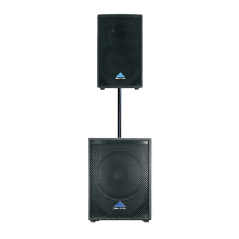
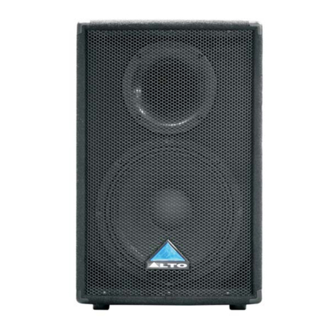
Alto MS8 User manual

^ô.LTo
MUSIC, PASSION, DESIGN
&ww&K*$ ffiÆw&$,&&
IfrSglilSg A/Mr r 2S/Mr r 2SA
SPEAKER ENCLOSURE
PASS'YE /ACTIVE MODELS
www. altopnoaudio. com
Vension '1 .'1 Apr" 2009
English

^ffia
TO REDUCE THE RISK OF ELECTRIC SHOCK
PLEASE DO NOT REMOVE THE COVER OR
THE BACK PANEL OF THIS EOUIPMENT.
THERE ABE NO PARTS NEEDED EY USER
INSIDE THE EOUIPMENT. FOR SERVICE,
PLEASE CONTACT OUALIFIED SERVICE
CENTERS.
fi ffis s)'rbol. wneneven Jsed. âlerrs you co ti'e
/f\ presence of un-insulaced and dangerous volLages
within the pnoduct enclosure. These are voltêges that
may be sufficient to constitute the risk of electric
shock on death.
fi ffi. symbol. whenever useo. ale'ts you to
L\ irrporLanL openaLing and mainlenarce insE.uctiors
Please nead.
g Pnotective Ground Terminal
.' AC mains [Alternating Current]
I Hazardous Live Terminal
ON: Denotes the pFoduct is tunned on.
OFF: Denotes the product is turned off,
CAUTION
Describes pnecautions that should be obsenved to
prevent damage to the pnoduct.
1. Read this Manual carefully befone openation,
2. Keep this Manual in a sefe place. A
3. Be awane of ail wannings reponceci /l\
with tnis symbol. ,/ a \
4. Keep this Equiprnent away from waten and
moistune.
5, Clean it only with dny cloth, Do not use
solvent on othen chemicals.
6. Do not damp on coven any cooling opening,
lnstall the equipment only in accondance with
the Manufactuners instructions.
7. Powen Conds ane designed for youn safety. Do
not nemove Gnound connectionsl lf the plug
does not fit your AC outlet, seek advice from
a qualified electnician, Pnolect the power
cond and plug from any physical stness to
avoid risk of electric shock. Do not place
heavy objects on the powen cond. This could
cause electnic shock on fire.
8. Unplug this equipment when unused fon long
peniods of time on during a stonm.
9. Fefer all service lo qualified senvice pensonnel
only. Do not penform any senvicing othen than
those instnuctions contained within the
Usen's Manual,
O. To prevent fire and damage to the pnoduct,
use only the necommended fuse type as
indicôted in this manual. Do not shont-cir cuit
the fuse holden Befone replacing the fuse,
make sune that the pnoduct is OFF and
disconnected fnom the AC outlet.
X
I
WARNING
To neduce the nisk of electric shock
and fire, do not expose this equipment
to moisture on rain,
Dispose of this product should
not be placed in municipal waste
and should be separate collection,
1'l . Move this Equipment only with a cant,
stand, tnipod, on bnacket,
specified by the
manufactunen, oT
sold with the
Equipment. When
a cant is used, use
caution when
moving the cant /
equipment
combination to
êvoid possible
injuny from tip-oven
12. Permanent hearing loss may be caused by
exposure to \ extremely high noise levels.
The US, Govennment's Occupational Safety
and Health Adrninistration IOSHAI has
specified the penmissible exposune to noise
level.
ïhese ane shown in the following chant;
HOURS X DAY
I
6
4
3 '1,
2
SPL EXAMPLE
SIO Small gig
92 train
95 Subway train
97 ., .High.level Cesktop .monitors
'lOO Classic music concerÈ
1,5 102
1 105
o,5 110
O,25 or less 1 15 Rock concert
Acconding to OSHA, an exposune to high SPL in
excess of these limits may nesult in the loss of
heat. To êvoid the potential damâge of heat, it is
necommended that Pensonnel exposed to
equipment capable of genenating high SPL use
heaning pnoLection while such equipment is
unden openacion.
The appanatus shall be connected to a mains
socket outlet with a prctective eanEhing
connection.
The mains plug or an appliance couplen is used
as the disconnect device, the disconnect device
shall nemain readily oper able.

Make all initial connections with all the equipmenË powened off, and ensure that
all the main volume controls are turned completely down.
1J. Connect one side of the speaken cable to the output CHA/CHB or Binding
PosE of youn steneo powen amplifier and the other side Ëo the input socket
of youn speaken cabineÈ.
2). Complete other connections as illusÈrated.
31. Tur"n on your mixen firsE, Ehen the stereo powen amplifien
41, Turn up the volume controls of your amplifien to about 7O%.
5). Use PFL function uo geË Ehe proper input level for the mixen, and adjust
Èhe main mix level control to manipulate the outpuË level.
6). Aften using, Èunn off youn steneo power amplifien finsË, Ëhen Èhe mixen
Speaker Cable Speaker Cable
Power Amplifier
Bight
Main Mix
Output

1. INTRODUCTION
2. SPEAKEH CABINET OUICK START
3. HOOKUP DIAGBAMS
4. WIFE CONNECTIONS
5. RIGGING
6. FREAUENCY FESPONSE
7. PANEL DESCBIPTION-MS8A/MS12SA
8. PANEL DESCFIPTION-MS8/IVIS'I 25
9. TECHNICAL SPECIFICATION
10. WARRANry
1
a
4
6
7
o
11
13
14
16
Thank you very much fon expnessing youl'confidence in ALTO products by put"c-
hasing MS8/MSBA/MS1ZS/MS12SA speaker system. The MS senies cabinets
ar e specifically designed for using in hi-quality penfonmance site and the pnecise
sound reinforcement commencial place. uses trapezium configuration which
gneatly decreases the nesonance of the standing wave in the cabinet. These
cabrnets uses hi-density matnix spr"ay-paint technics and the bottom bnacket
design which make mounting quickly and Flexibly. The HF compnession driven and
vented LF for fully professional penfonmance.
The MSBA/MS12SA speaker cabinets include some exclusive innovations such as
switch mode power supply and digital powen cincuitt'y (in selected modes) that
make them the lightest power"ed cabinets of this kind even made.
The MS full range models include anothen Alto innovation: The MODELLER.
Thanks to this cir"cuitry, Usen can select 1 6 different tastes and applications.
The 1 6 kinds of sound pnesets especially thought for application with ot' without
subwoofen, for voice optimised application, fot' Disco Music, for iazz, fon Rock &
Roll among others.
Enjoy your MS8/MSBA/MS12S/MS12SA speaker cabinet and make sune to nead
this manual canefully before operation.

Two active speaker in stereo operation
LINE IN
Multiple active speakers with the same stereo source
MIXEF

Make all iniÈial connections with all the equipmenE powered off, and ensune
thaÈ all the main volume controls are tunned completely down.
11. Connect one side of the signal cable at your audio mixen inLo output
left /right twith Stereo-Jack or XLR) and the other side of Ëhe cable into
the line input [Stereo-Jack] of your active speaken cabinet.
2J. Connect the powen cond to mains.
31. Tunn on your mixen firs!, then the acEive speaken cabinets.
41. Tunn up the volume control of the active speaker cabinets.
51. Use PFL function to get the propen input level for the mixer, and adlust
the main mix level control to manipulate the outpuÈ level.
6). Aften using, tunn off youn active speaker cabineEs finsÈ, then the mixen
Signal Cable Signal Câble

-.For Active Speaker Cabinets
As to these cincumstances,audio connections is mostly intended for the signal
flow,so,determine the wine configunation acconding to your. neal application
system and its connecting facility.Normally,you have the following choices:
. Balanced
@@@
@
. Unbalanced
@
@
-.For Passive Speaker Cabinets
Please only use the powen connectons to make connections with other signal sounce
equipment fon the passive speaken cabinets. The power connecton has four terminals:
1+, 1-, 2+, 2-,
ffi->@
1+/1 - are used to connect the Speaker'+/Speaker-, and 2+12-
ln our cabinets, only
ane not used.
À
-l t-

The MS8/MSBA speaker cabinet also provides Èhe bracket fon fixed installation,
How to use them?
1 ). lnventory
Before beginning installaEion, inventory kit to items listed.
Item Q'ty Description
I 1PCS MH-88 Bracket / Wallmount
II 2PCS Screw, M10*30*1.5P8, Black ( in the cabinet)
III 2PCS Washer, Neoprene, 1,5t* p 35mm
Warning:
lnstallation should only be done by an experienced Èechnician. lmproper
installation may cause serious injury . The surface whene the bracket/cabinet
is to be fasÈened must have enough structural integrity.
2). Mounting the Bracket
Due to vanious consËruction methods and matenials used today, the handwane
for secuning the bracket to the mounting surface is not supplied. lt is recom-
mended that you consult a building professional for the proper mounting
hardware before mounting the bracket.
3).Removing the Shipping Hardware, Flemove the flat head screws from the top
and Èhe bottom of the cabinet using a smm wrench.
^ë.

4).Choosing which slot to use there are three slots in each bracket apm. use
the fonward slot [as shownJwhen the cabinet is facing perpendicular to the
bnacket mounting sunface.
5).Hanging the Cabinet
A. Place a neoprene gasket on the bracket's lower arm. Centen it on the
appropriate slot.
B. Position the cabinet between the bracket arms.
G. Align the bracket's top slot Èo the cabinet's M10 threaded hole.
D. Holding the cabinet in position, insent the screw Ëhrough the brackeE slot
and into the cabinet's top threaded hole and hand tighten.
E. Repeat step D through the bottom bracket hole.
F. Position cabinet and tighten both screws wiuh a Smm wnench.

MSSA
d
B
.S P
'. 1
M58
d
B
S
P
.L
20 50 100 200 500 1k 2k 5k 10k 20k
Hz
11
11

d
B
S
P
L
+11
+1
+
+11
+'l
+9
+8
+7
+6
MS 12SA
MS125
d
B
S
P
L

ACTIVE FULL RANGE: MS8A
(1] BI-POI.AF MAIN POWER SWITCH
(2] AC POWER SOCKET WITH MAIN FUSE
(3) GROUND SWITCH
(4] CLIP INDICATOH HED LED
(51 LINK OUT ON XLH CONNECTOH
16] LINE INPUT ON COMBO CONNECTOR
17] MAIN VOLUME CONTROL
(8) POWEF SWITCHUNG BUTTOM
19] PRESETS SELECTOH
Via this knob, you can select Èhe night effect you wish to perform. There
ane roral 16 options for you, JAZZ CLUB+SUB, VIHTICAL SUB, STAGE
MONITOR, JAZZ CLUB, CONCEHT HALL+SUB, DISCO, VOCAL, ROCK &
ROLL, FI.AT DHUM KICK, ANTIHUMBLE, CONCERT HALL, AHENA+SUB,
LOUDNESS, HOCK & ROLL+SUB and ACOUSTIC.
(6) (5)(4) (7) (e)
(2) (8)(1)
.^,LTO MsEA
I cû---E I
r-;-@-:-
I A t":E*tA I
lramH:4.\l
r-=:Æ=l
I -ÉÈ}É-- I
II
**â -.;(€
&

Nfï 7. nANEL DEscntpnoN,MstzsA
il"%l
ACTIVE SUBWOOFERS: MS1 2SA
tl) ON-OFF main power switch
Ql lnput AC power socket with main fuse
t3l POWER, Gneen LED, indicate ON status
A) BYPASS Switch Select the Hiqh pass filten or by pass
t5l Ground Lift Switch
16] LINE IN RIGHT.ON XLR CONNECTOR
t7) LINE IN LEFT/MONO ON COMBO CONNECTOtr
(8] LINK LEFI/BIGHT ON XLR CONNECTOR
(91 SIGNAL/LIMIT, Red LED, indicate ON status
(1Ol VOLUME main powen amplifier control
(111 PHASE Switch Revense the Polanity of the subwoofen output
t12l OUT LEFI/RIGHT ON 2xXLF CONNECTOF
. 113] POWEF SWITCHUNG BUTTOM
!À
t6l
t7) t1l
(21
(31
A)
t5l
r9l t10l (1) t12)
lgg--l ' é vd I LEFr vo{o
:Ajo\o-JnFlLoL--J
;?k-P.rË..,,hî#
l||[
I[|[
t[|l
[0tI
t[|l
t[[i
t[|l
I[|l
[|t!
'&uto rrrsrzse

CONNECTION PLATE
PASSIVE FULL RANGE: MS8
(1t TNPUT
Beceive the powen coming from an external power amplifier.
ISPK +'1l-1 connected: +21-2 not connectedl
tz! THRU
Dinect LINK fon connect in panallel a second speaken cabinet.
ISPK +1/-1 connected: +21-2 not connectedJ
Besides, the passive crossoven included the electnonic pnotection
on the dniven
<O
MS8
@ souronerlroacevENTspEAKERsysrEM E
POwER HANDLINGI
CONTINUOUS - 150 Warc
PEAK 300 Wars
IMPEDANCEi
8 Ohm
*I \gn
*"Ic<3
'*::li: **':::il li. ]:*
ruffi
^"1- ."- - ti":
lel
a
<O
oo
MS12S
SOUNO REINFORCEMENI SPEAKER SYSTEM
@o
POWER HANOLING:
coNllNUOÙS s00wars
MPEDANCE 4 OhM
Mâx SPL: 120d8 âl 1ml
-I \e'
-"Iceil
OESIGNEDANO DEVELOPMENT N TAL\
ffiffi
tttt
(1) (2) (a) (b)
PASSIVE SUBWOOFERS: MS125
al. INPUT; Beceive the signal coming from an external amplifien
ISPK +1/-1 connected;+21-2 not connectedJ.
bl OUTPUT: Powen output fon satellite speaker, unden passive cnossover
filter"ed at 125N2 ISPK +'ll-1 connected: +?l-2 not connected).

Active System Type
tl:litttBP'YçlFY:FT::,,,,r:iii:ill:
Frequency Response
l::l :l:'Maxiiilum. gPL @ ::l $.,'
Coverage (HxV)
,il:::l:TlàïiôdUcéit-- """
Transducer High
ri::iuAqtit€:C-rcttggvert::::rii::l
lnput Connector
ii.:iritnptlt.9ênsft iitty r, rl:llliiii:
Extemal Control
Enclosure Construction
, Mqunting / s-qlpen€ion
Dimensions (HxWxD)
:: Nelwêight .,i , . :.:. :
Shipping Weight
Passive System Type
.....POw.q,Systqm,,,:..:,.,':::rll,:
Frequency Response (-'10d8)
Sensiùvity ('lw @ 1mt)
lmpedance:
Maximum SPL @ 1m
Coverage (HxV)
Transducer Low
Transducer High
. Passive Crossover
lnput Connectors
2-way Bi-Amp, with MODELLER
:: ::l:i35QW;toW:çLAqgpl65w+J!iSËçLAS€tABttr!:gi{!:1;,11...-,,,,, ..,,,,,,,,, ,l
2OOW+OW CLASS D/35W-H| CLASSABin Continuous l. '
MODELLER preseis setting
] lii i : :1 !$dB: Osn1l1uousl123dB' Péâk (Câculate61,, " :'
70'x 70'nominal
I ::t::t:8r VÛtbter;:1;5"voiôêreoil,'with:ooriiiiêveni'itrtiôii:'l:lii:::r I ::i:
1" Neodymium on Spherical Horn (Tractrix contour)
: rr:z.KHe:Undeiê*ito6p1o."ttt::,,::tll::i.r: ::.]..:.ltt:::,'ir:::r,rr:t:::
LINE-COMBOi LINK-XLR-F Balanced (1 Skohm)
. ir:Linçt:*,0d8|::::ti:i::r ,,:t:tlirr, 'rt. ,,,:.'.:.:,' .',::,,:,a,,:.'',,\',,,:;
MODELLER with 16 Preset / Volume Control/ Power ON with
Green LED/ Clip Limiter with Red LED/ Ground Lift.
MDF wood cabinet, glued and reinforced, black painted, one metal
handle and rubber foot.
, ,i:,.,Two.pgint fof:€qFpefgjgn, of.rg rnelal,æ!e"!OunJ;tgpJisnal:'t,tqçl(el;:f,::ii,l:
493 x 304 x 293 mm (1 9.41" x 11 .97 x 11 .54")
12.O6kgl26,03, lbs,' .'' ."; rli,.::II:r:::
'14.56k9 / 32.03 lbs
8': ?:wây Passive Speq(erÇAbineJu,:,,,.,r,,::::,,, r : :,t,r
2-way Passive
,,, 150W.çontinuousl,390W peak. ,t:-:rlir, r 'r....l:
67Hz-19kHz
'.,,,Sa,sdgSp'l' . 1, , ::, . ":,:,':',' . :" ,.',.
8 O(nominal)
. 116d8 continuoudllgdB peak (Calculated)
70"x 70'nominal
ri,ii::Aliv{i6rifer,r1,*toiôirôit; ùithtrioùpiâven$iâilon itilll:r:: I:::: . '
1" Neodymium on Spherical Horn (Tractrix contour)
Z.21ûzallidP,tocl,with HF protection .
Two Parallel SPK NL-4 for INPUT/ THRU
lr,lDF wood cabinet, glued and reinforced, black.pâinted;
:::r::ônâ'iiiitiât hâiiâle alitt,nronerfoôt . tt"',':.:,:;;;l',,,;,:;,:",t;;
Two point for suspension , one standard pole-mount plus a
optional bracket.
493 x 304 x 293 mm ('19.41' x 11 .97 x 11 .54")
11,29ks t 24.84 lbs ,
13.79 ks / 30.34 lbs
,tFncl!*tB æ.,nsttu|otio,lLl,
Mounting / Suspension
Dimensions (HxWxD)
r::riiet rvveiôht, t :"t ::',', r : ::,.i,:, r :::.,,,,t:
Shipping weight

Power System
'l I lFiequ encry- Rêsponse,É i ôii B )
Maximum SPL @ 1m
rTransduQe1:,LgW,.,,,11.
Active Crossover
lnput Connéctor
lnput Level
" :Éiternal Côôtrol
Power Supply
''Enclosure,Oônstruction:,. r' i
Mounting
l.a.ôimensioiii,rHxWxD),it :,::t,,.
Net Weight
Shipping Weighl
12" Active Subwoofer Speaker Cabinets_
350W Clâss D in EIAJ/300W Class D in Continuous
47,1t'125H2
1 21 dB Continuous/1 24dB Peak (Calculated)
12" Woofer, 2.s'voice coil, with double ventilâtion
HPF 80Hz under analog processor
L-R lnput (Combo/ XLR-F) / L-R Link (2-XLR-M) /
L-R Output (2-XI.R-M) Balanced (1skohm) 1,
L-R lnput Line 0dBu
Voitnre Controll Phase Switchr/ HPF-80.H2,By-Passl:Poùèr
ON with Green LED/ Clip Limiterwith Red LED/ Ground Lift.
120-240 Volf, in Swilching Power mode.
1smm Plywood cabinet, glued and reinforced, resistant
black paint, metal grille, rubber foot.
One metal standard pole-mount plus one metal handle
3t0*i530 x 4sorix,m (1 4.sTt.ta.Z6,.a7 i Jl;gp') ..:,rrii:l:r:,
18.6k9 / 41 .01 lbs
20.8kg / 45.86 lbs
1 2'lPassive Sûb\iùoofer Speàkér Cabinet
300W continuous
47Hz-16OHz
96dB SPL
4 çr(nominal)
120d8 continuous/123dB peak (Calculated)
12" Woofer, 2.5"voice coil, with double ventilation
1 25Hz at 6dB/oct
1Smm Plywood cabinet, glued and reinforced, resistant
blAçli,Fa,int, m,e,lfl,Srille, rùbb€i:Joot. :,:::i:i.':;,: ::,rr:i::::::r:
INPUT-SPK NL-4 / OUTPUT-SPK NL-4, for Satellite Speaker
One metal standard pole-mount plus one metal handb
370x 530 x 480 mm (14.57" x20.87 x 18.90")
Power System
1;f,requen cy:Response, (i 10dB )
Sensitivity (1w @ 1mt)
lmpedance:
lvlaximum SPL @ 1m
:'Transducei:Low ::::lr".,
Passive Crossover
Enclosure _Gonstruction
':l:::: ::a:::.... r:l::l: ' ,
lnput Connectors
Mounting
Dimensions (HxWxD)
;,iiieiweighi,,,r', :,,t::l::
Shipping weight 1q:10:kg / 39:9.gilbè 'li
20.30 kg / 44.8 lbs

IO.WARRANTY I
1. WARRANTY REGISTRATION CARD
To obtain War nanty Senvice, the buyer should finst fill out and netunn the encl-
osed Wannanty Registration Cand within 'l 0 days of the Punchase Date.All the
infonmation pnesented in this Warnanty Registration Card gives the manuf-
acEuner a betben undenstanding of the sales status, so as to purporb a mone
effective and efficient after-sales warnanty senvice.Please fill out all the infon-
mation car"efully and genuinely, miswniting or absence of Èhis card will void youn
wannanEy senvice.
2. RETURN NOTICE
2. 1ln case of retunn fon any warranLy service, please make sure that the pr.-
oduct is well packed in its oniginal shipping canÈon, and it can pnotect youn
unit fnom any othen extna damage,
2.2 Please pnovide a copy of your sales neceipt on other proof of punchase with
the netunned machine, and give detail
2.3 A brief description of the defect will be appreciated.
2.4 Please prepay all the costs involved in the netunn shipping, handling and
insurance.
3. TERMS AND CONDITIONS
3. 1 ALTO warrants that this product will be free fnom any defects in mat-
enials and/or wonkmanship fon a peniod of 1 yean fnom the punchase date if
you have completed the Wanranty Registnatlon Cand in time.
3.2 The warnanty senvice is only available to the oniginal consumen, who punch-
ased this pnoduct dinectly fnom the netail dealen, and it can not be transfenned.
3.3 Duning the warnanty senvice, ALTO may nepair on replace this pr"oduct at
its own option at no change to you fon pants on fon labon in accordance with
the night side of this limiÈed wamanty.
3.4 This warnanty does not apply to the damages to this pnoduct that
occunned as the following conditions:
. lnstead of openating in accordance with the user's manual thonoughly, any
abuse on misuse of this pnoduct.
. Nonmal tean and wean
. The product has been altened on modified in any way.
. Damage which may have been caused eithen dinectly on indinectly by another
3.5 ln no event shall ALTO be liable fon any incidenEal on consequentialdamages.
Some sËates do not allow the exclu-sion on limitation of incidental or conse-
quential damages, so the above exclusion or limitation may not apply to you.
3.6 This warnanty gives you the specific nights, and these rights ane
compatible with the staÈe laws, you may also
have other statutory rights that may vany fnom state to state,


SEII(AKU TECHNICAL GROUP LIMITED
NO. 1, l-ane 17, Sec. 2, Han Shi West Foad, Taichung 4fJ1Ii1, Taiwan
wvuwaltoproaudio,com Tel: 8864223137 37
All |ights neserved to ALTO. All featunes and content might be changed
without prior notice, Any photocopy, translation, or reprcducÈion of parf of this
manual without wriËten permission is forbidden. Copyright @2OOS Seikaku Group
NF03258-1.1

^ô.LTO
MUSIC, PASSION, DESIGN
ûwtrs&'$ *TÆfitgÆ{
M'g/iltsgA/iltt I 2s/ilts r 2SA
SPEAKER ENCIO.'URE
PASS'VE /ACTIVE MODELS
www. alLopnoaudio. com
Vension 1.1 Apn 2009
English
Other manuals for MS8
2
This manual suits for next models
3
Table of contents
Other Alto Enclosure manuals

Alto
Alto PASSIVE User manual

Alto
Alto ELVIS 15.2XL User manual

Alto
Alto PS 4LA User manual

Alto
Alto SR400P User manual

Alto
Alto ELVIS MKII User manual

Alto
Alto PS4/5 LITEPACK ACTIVE SPEAKER User manual

Alto
Alto ACTIVE User manual

Alto
Alto ELVIS MKII User manual

Alto
Alto MS8MA User manual

Alto
Alto MS12A User manual