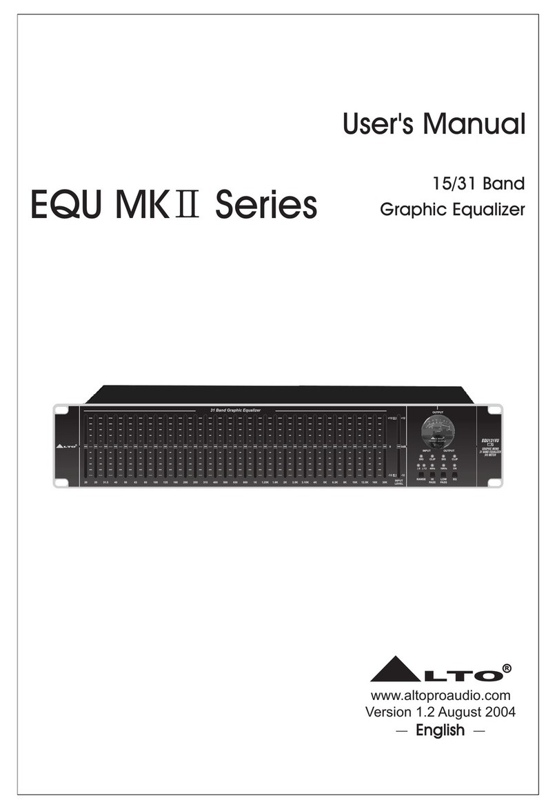
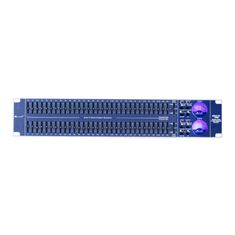
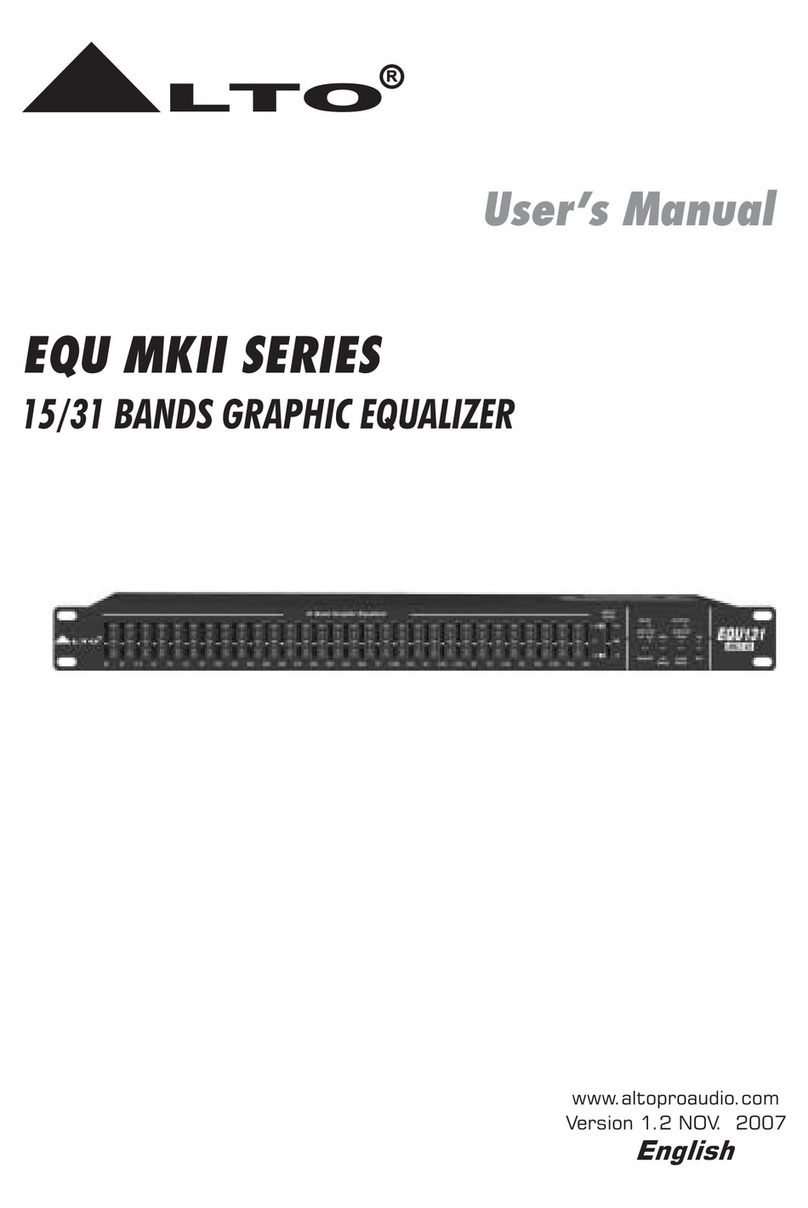
Alto EQU231- MKII V2 User manual

www.altoproaudio.com
!!!!!!!!!!!!!!!!!!!!!!!!!!!!!!!!!!!!!!!!!!!!!!!!!!!!!!!!!!!Version 1.0
MODEL: EQU231- MKII V2
Revised on Jan,2010

CONTENTS
1. Introduction..................................................................................................................1
2. Specification.................................................................................................................2
3. Block Diagram..............................................................................................................3
4. Schematic Diagram.....................................................................................................4
5. Wiring Diagram............................................................................................................7
6. PCB Layout.................................................................................................................8
7. Test Procedure...........................................................................................................11
8. Exploded View & Mechanical Parts List.....................................................................15
9. BOM List....................................................................................................................17

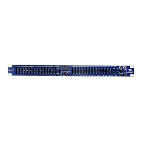
The EQU231-MKII V2 Graphic Stereo 31-Band Equalizer is an extremely musical and
flexible Graphic Equalizer, based on many years of experience and designed to provide a
permanent precise equalization to musician, performer, and studio engineer. It can be used
wherever is requested to modify the frequency “contour” of a sound and can offer a solution
to many common sound problems and allows the user to use the creativity to obtain nice
results in terms of sound characterization.
The EQU231-MKII V2 Graphic Stereo 31-Band Equalizer Features:
Constant Q circuitry with a 3% center frequency accuracy
Control range +/-6dB/+/-12dB selectable
Active balanced and unbalanced input and output connectors
Variable input level control
Signal clop pilot
Ground “LIFT” switch to disconnect signal ground from chassis ground
Power off automatic bypass function
Line voltage selectable robust and compact design
Manufactured under QS9000, VDA6.1 certified management system
1. Introduction
--- 1 ---

Type EQU231-MKII V2 2*31-Band: 1/3 Octave, ISO spacing(2H series)
Slider Travel 20mm with positive centre detent
Range +/-6dB or +/-12dB selectable
Active balanced XLR and 1/4'' TRS
Unbalanced RCA
20k Ω(bal.)
15k Ω(unbal.)
Maximum input level 14 dBu
Active balanced XLR and 1/4'' TRS
Unbalanced RCA
Output impedance <600Ω
High pass filter 40Hz(12dB/Oct)fixed-button type
Low pass filter 16KHz(12db/Oct)fixed-button type
Frequency response 20 Hz to 50kHz at -1.5dBu
THD+N% <0.01% (@1kHz, all VR at middle position)
S/N Ratio 110dB
95V -120V AC -60Hz
220V-240VAC -50Hz/60Hz
Consumption 18W
Dimension 483(W)*220(D)*88(H)mm (19''*8.66''*3.5'')
Power supply
Input impedance
Output connections
Input connections
2. Specification
--- 2 ---

3. Block Diagram
--- 3 ---

4. Schematic Diagram
--- 4 ---

--- 5 ---

--- 6 ---

/ % ,
/ % ,
5 " % (
'
' (
' (
6
/$
5. Wiring Diagram
--- 7 ---

-
-- 10 -
--
6. PCB Layout
--- 8 ---

-
-- 9 -
--

--- 10 ---

EQU231-MKII V2 Finished Product Test
Test Instruments
1. AP (Audio Precision)
2. Dual-track oscilloscope
Instrument setting
1. Set proper AC input voltage
2. Connect the output signal of AP to the input of EQU231-MKII V2
3. Connect the output of EQU231-MKII V2 to the input of AP
Adjustment according to following procedures
1. Set the potentiometer of 31-band EQ in center, set the input level at 0dB, all buttons out
2. Turn input level to maximum, the output level and the distortion shall be as following
3. Set INPUT LEVEL at minimum, the output level shall be and distortion shall be as following
7. Test Procedure
--- 11 ---

4. Adjust the input level so that the AP output is 0dB, the frequency response is as following
5. Adjust the input level so that the AP output is 0dB, press the HI-pass button and the frequency
response is as following
6. Adjust the input level so that the AP output is 0dB, press the low pass button and the frequency
response is as following
--- 12 ---

7. Press EQ button down, keep RANGE out and the LED indicates +12, adjust slide buttons to
maximum and minimum, measure the frequency response independently and the curve shall
be as following
8. Turn off the AP input signal and set input level as maximum, the AP setting is as following, now
it shall be no more than -82dB
--- 13 ---

9. Turn on the AP input signal, and set the input level at maximum, the AP setting is as following,
the maximum non-distortion level is +28dBu+/-1dB and distortion is 1%
10. Now, the S/N shall be no less than 110dB
11. Connect AP input and output to Channel 2,repeat steps 1~10
12. All slides shall be set in center and all buttons out before shipping
~Test Completed~
--- 14 ---

8. Exploded View & Mechanical Parts
List
--- 15 ---
MODEL No: EQU231-MKII V2

S/N Part No Description Specification Qty
1 MB03213 Chassis EQU231MKII 1
2 MB03220 Rear panel EQU231MKII 1
3 MC00578 Top cover EQU231MKII 1
4 MA04793 Front panel EQU231MKII ALTO 1
5 HC00015 AC socket (S)315-B(with AC selector) 1
6 TC00212 Fixed voltage transformer PT-231-II-230V 1
7 MG00127 Color screw M4*8 2
8 MG00042 Black plated screw M3*10 2
9 NI00315 Pwer switch 5*5*9(inner3.3*3.3) 8
10 MG00061 Lback plated screw M3*10 12
11 NI00501 Adhesve cushion 12.7*3t(SF-004) 4
12 HI00026 Power SW RA12KKATO F2P 1
13 MG00025 Black plated screw M3*6 24
14 MG00041 Black plated screw M3*6 20
15 ME00016 Color nut 4mm 1
16 MF00038 Spring washer ψ4*ψ7*1t 2
17 MF00048 Outer fear washer ψ4*ψ8*0.5t 3
18 HK02068 K-PCB P-EQU231FP-II-DIP 2
19 HK02063 K-PCB P-EQU31EQ-II-DIP 2
20 HK02065 K-PCB P-EQU31PU-II-DIP 1
21 HK02066 K-PCB P-EQU31PU-II-1-DIP 1
Mechanical Parts List
--- 16 ---

Class Part No Description Specification Insert location Remark
PF01529 EQUALIZER EQU231-MKⅡV2_ALTO_230V
├0001 MB03220 rear board-RS-ACT EQU231-MKⅡALTO_V1.5
├0002 MC00578 top cover EQU231MKⅡ
├0003 MA05527 panel EQU231-MKⅡV2 ALTO_V1.1
├0004 HD00021 glass tube fuse 100mA 250V φ5.2*20mm CSA/S/UL/VDE
├0005 TC00212 transformer-RS PT-231-Ⅱ_115/230V
├0006 MG00262 screw M4*8 1.fix transformer
├0007 MG00042 screw M3*10 1.fix AC socket
├0008 NI00315 power switch button-cambered surface 5*5*9(inner 3.3*3.3) 1.function key
├0009 MG00061 screw-RS M3*10 1.fix AC socket
├0010 HA01333 signle terminal wiring CF:W76 150mm UL1015 18AWG green/yellow 1.AC socket GND
&PU board GND
├0011 HA00861 power cord Europe 3P LT-312+LT-501
├0012 NI00240 sleeve φ2.5*10mm
├0013 NI00252 sleeve φ4*20mm
├0014 NI00218 cable tie ALT-102SB
├0015 NI00501 self-adhere foot cushion 12.7*9*3t(SF-004)
├0016 NA00137 clip-chain bag 5*7
├0017 NA00862 PE bag-RS 0.04t*580*300 mm
├0018 HI00026 power switch-RS RA12KKATOF 2P 1.PWR SW
├0019 MG00025 screw-RS M3*6
front board*6,top
cover*10,rear
panel*3,front
panel*7,bracket*4
├0020 MG00041 screw M3*6 1.fix PCB
├0021 ME00016 color nut 4m/m 1.fix GND and
transformer
├0022 MF00038 washer-RS φ4*φ7*1t 1.fix GND
├0023 MF00048 washer-RS φ4*φ8*0.5t 1.fix GND
├0024 HA02195 wire-RS 3P-3P 120mm UL1015 18AWG
├0025 HK02066 PC board-RS P-EQU31PU-Ⅱ-1-DIP
│ ├0001 CC00039 mylar capacitor 0.1uF/100V 3% C18,C19,C20,C21,C47,C22,C23,C24,C25
│ ├0002 CH00053 laminated capacitor 0.1uF/50V Y5V PH5mm C34,C35
│ ├0003 SA00098 rectifier diode 1A/400V IN4004 D1,D2,D3,D4,D5
│ ├0004 CC00015 mylar capacitor 0.0056uF/100V 3% C38,C39
│ ├0005 CB00065 electrolytic capacitor 470uF/25V φ10*16mm C50,C51
│ ├0006 CB00134 electrolytic capacitor 1000uF/35V 105℃SH φ12*21mm C48,C49
│ ├0007 HC00112 balance MIC jack 99M-107SP-1-2 90° PUSH PJ1
│ ├0008 HC00111 balance MIC jack 99M-108SP1 PJ3
│ ├0009 HC00108 stereo MIC jack φ6.3 stereo LJB0661-6 PJ2,PJ6
│ ├0010 HC00241 RCA jack-RS RJ-1081-01-0500A PJ4,PJ5
│ ├0011 SD00077 integrated circuit-RS L7815CV(TO220)/(ST/MOROCCO) U1
│ ├0012 SD00079 integrated circuit L7915CV(TO220)/(ST) U2
│ ├0013 MI00256 heat-sink 25*15*10.6-1PIN SCL-2020
│ ├0014 MG00162 screw M3*8
│ ├0015 MF00037 washer φ3.2*φ5*0.8t
│ ├0016 NC00167 mica-RS 13*18(φ3.6)TO-220
│ ├0017 HC00172 connector(male) 3P 3.96mm 180° CN3
│ ├0018 HC00256 connector(male) 5P 2.0mm 180° CN2,CN10,CN1
1.reverse insert
direction of
CN1&CN2
│ ├0019 HC00257 connector(male) 6P 2.0mm 180° CN6,CN7
│ ├0020 HC00078 connector(male) 4P 2.5mm 180° CN4
│ ├0021 HI00008 relay RY-12W-K 12V
│ ├0022 HA01918 jump 4mm JP1,JP2
│ ├0023 SA00124 zener diode 1/2W 12V 12A2 ZD1
│ ├0024 AC00603 lead free soldering bar S100
│ ├0025 SA00175 Schottky barrier diode 1A/40V 1N5819
│ ├0026 HK02064 PC board P-EQU31PU-Ⅱ-SMD
│ │ ├0001 RD00282 SMD precise resistor 1/10W 1.00KΩ±1% 0603 R39,R40,R8
│ │ ├0002 RD00272 SMD precise resistor 1/10W 10.0Ω±1% 0603 R26,R33
│ │ ├0003 RD00288 SMD precise resistor 1/10W 6.81KΩ±1% 0603 R32,R29
│ │ ├0004 RD00214 SMD precise resistor 1/10W 10.0KΩ±1% 0603 R3,R5,R6,R17,R18,R55,R15,R25,
R27,R35,R36,R56,R13,R14
│ │ ├0005 RD00219 SMD precise resistor 1/10W 20.0KΩ±1% 0603 R42,R43,R44,R45,R10,R11,R54
│ │ ├0006 RD00294 SMD precise resistor 1/10W 24.9KΩ±1% 0603 R46
│ │ ├0007 RD00290 SMD precise resistor 1/10W 47.5KΩ±1% 0603 R20,R30,R31,R34,R38,R37
9. BOM List
--- 17 ---

Class Part No Description Specification Insert location Remark
│ │ ├0008 CI00058 SMD ceramic capacitor 0603 82PF/50V NPO ±5% C11,C12
│ │ ├0009 CI00063 SMD ceramic capacitor 0603 470PF/50V NPO ±5﹪C42,C43
│ │ ├0010 CI00030 SMD ceramic capacitor 0805 1uF/16V Y5V-0805(2012) C36,C37
│ │ ├0011 SG00210 SMD integrated circuit LM339DT/(ST) IC5
│ │ ├0012 SE00011 SMD rectifier diode RLS4148 0.5A (LL-34) D11,D6,D7,D8,D9,D10
│ │ ├0013 CI00075 SMD ceramic capacitor 0603 0.1uF/50V Y5V +80,-20% C14,C15,C16,C17,C26,C27,C28,
C29,C30,C31,C32,C33,C100
│ │ ├0014 SG00122 SMD integrated circuit-RS-ACT NJM4580M-TE3(SOP8)/(JRC) IC6,IC1,IC2,IC3,IC4
│ │ ├0015 SF00056 transistor MMBT3904(SOT23)/(PHI) TR9
│ │ ├0016 RD00274 SMD precise resistor 1/10W 100Ω±1% 0603 R53
│ │ ├0017 RD00301 SMD precise resistor 1/10W 12.1KΩ±1% 0603 R12
│ │ ├0018 RD00264 SMD precise resistor 1/10W 60.4KΩ±1% 0603 R41
│ │ ├0019 RD00224 SMD precise resistor 1/10W 100KΩ±1% 0603 R7,R57
│ │ ├0020 CI00059 SMD ceramic capacitor 0603 100PF/50V NPO ±5% C45
│ │ ├0021 RD00292 SMD precise resistor 1/10W 1.00MΩ±1% 0603 R9
│ │ ├0022 CI00268 SMD ceramic capacitor-RS 0603 47PF/50V NPO ±5﹪C9,C10
│ │ └0023 HK04108 PC board P-EQU31PU-Ⅱ-AI
│ │ ├0001 HA01920 wire-RS 6mm J3,J39,J38
│ │ ├0002 HA01922 jump 8mm J9,J10,J11,J12,J4,J5,J6,J7,J8,J13,J36
│ │ ├0003 HA01925 jump 10mm J14,J15,J16,J17,J18,J19,J20,J21,J22,J23
│ │ ├0004 HA01928 jump 12mm J24,J25,J26,J27
│ │ ├0005 HA01930 jump 15mm J28
│ │ ├0006 HA01937 jump 18mm J29,J30,J31,J32,J33,J34,J35
│ │ ├0007 HA01931 jump 16mm J40
│ │ ├0008 RA01334 fixed resistor 1/8W 680ΩR51,R52,R47,R48
│ │ ├0009 RA01335 fixed resistor 1/8W 3.3KΩR49,R50
│ │ ├0010 RA00973 fixed resistor 1/8W 100KΩR19,R22
│ │ ├0011 RA01112 fixed resistor 1/4W 100ΩR24
│ │ ├0012 RA01413 fixed resistor 1/4W 2.7KΩR28
│ │ ├0013 RA01125 fixed resistor 1/4W 56KΩR1,R2
│ │ ├0014 RA01111 fixed resistor 1/4W 100KΩR23,R16,R21
│ │ ├0015 CB00242 electrolytic capacitor 22uF/35V φ5*11mm C1,C2,C3,C4,C5,C6,C7,C8,C13,
C46,C40,C41,C57,C58,C59
│ │ ├0016 CB00235 electrolytic capacitor 100uF/25V φ6*11mm C52,C53
│ │ ├0017 CB00193 electrolytic capacitor 47uF/16V φ6*7mm C54
│ │ ├0018 HB01179 PCB-RS EQU31PU-Ⅱ_VER070322
│ │ └0019 HA01919 jump 5mm J1,J2,J37
│ ├0027 CA00033 ceramic capacitor-RS 470PF/50V Y5E C44
│ └0028 RA00967 fixed resistor 1/8W 10KΩR4
├0026 HK02065 PC board-RS P-EQU31PU-Ⅱ-DIP
│ ├0001 CC00039 mylar capacitor 0.1uF/100V 3% C18,C19,C20,C21,C47,C22,C23,C24,C25
│ ├0002 CH00053 laminated capacitor 0.1uF/50V Y5V PH5mm C34,C35
│ ├0003 SA00098 rectifier diode 1A/400V IN4004 D1,D2,D3,D4,D5
│ ├0004 CC00015 mylar capacitor 0.0056uF/100V 3% C38,C39
│ ├0005 CB00065 electrolytic capacitor 470uF/25V φ10*16mm C50,C51
│ ├0006 CB00134 electrolytic capacitor 1000uF/35V 105℃SH φ12*21mm C48,C49
│ ├0007 HC00112 balance MIC jack 99M-107SP-1-2 90° PUSH PJ1
│ ├0008 HC00111 balance MIC jack 99M-108SP1 PJ3
│ ├0009 HC00108 stereo MIC jack φ6.3 stereo LJB0661-6 PJ2,PJ6
│ ├0010 HC00241 RCA jack-RS RJ-1081-01-0500A PJ4,PJ5
│ ├0011 HI00121 slide switch SCH-12-07 SW1
│ ├0012 SD00077 integrated circuit-RS L7815CV(TO220)/(ST/MOROCCO) U1
│ ├0013 SD00079 integrated circuit L7915CV(TO220)/(ST) U2
│ ├0014 MI00256 heat-sink 25*15*10.6-1PIN SCL-2020
│ ├0015 MG00162 screw M3*8
│ ├0016 MF00037 washer φ3.2*φ5*0.8t
│ ├0017 NC00167 mica-RS 13*18(φ3.6)TO-220
│ ├0018 HC00172 connector(male) 3P 3.96mm 180° CN3,CN5
│ ├0019 HC00256 connector(male) 5P 2.0mm 180° CN2,CN10,CN1
1.reverse insert
direction of
CN1&CN2
│ ├0020 HC00257 connector(male) 6P 2.0mm 180° CN6,CN7
│ ├0021 HC00078 connector(male) 4P 2.5mm 180° CN4
│ ├0022 HI00008 relay RY-12W-K 12V RL1
│ ├0023 HA02190 signle terminal wiring 150mm TP1
--- 18 ---
Table of contents
Other Alto Stereo Equalizer manuals

Alto
Alto EQU MK II Series User manual

Alto
Alto EQU Series User manual

Alto
Alto DIGAN2.14 User manual

Alto
Alto EQU231TWIN-MKII V2 User manual

Alto
Alto EQU MKII series User manual

Alto
Alto ALTO Q User manual

Alto
Alto EQU231VU-MKII User manual

Alto
Alto EQU MK Series User manual

Alto
Alto ALTO-Q User manual

Alto
Alto DIGAN2.7 User manual