21.10.2004
ALTO Danmark A/S
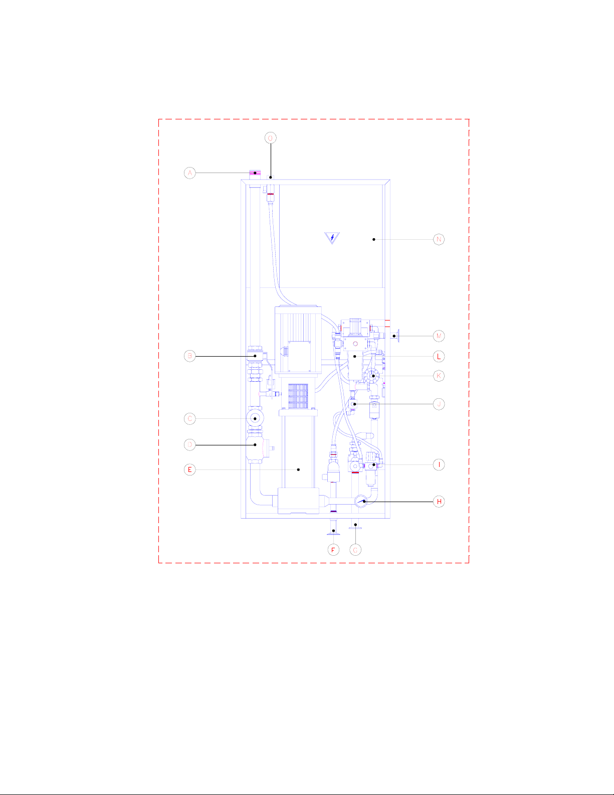
4. Security Devices
a) Closing valve for water (B on layout drawing page 4).
On the inlet pipe there is a closing valve in the cabinet by which the water supply
to the pump can be closed.
b) Strainer (C on layout drawing page 4).
On the inlet pipe of the pump a strainer is mounted to prevent impurities from the
water and the pipe work to get into the flow switch, the pump and the injector.
c) Flow switch (D on layout drawing page 4).
For control of the pump a flow switch has been mounted on the inlet pipe. The
flow switch activates the pump as soon as a flow takes place in the flow switch. If
all valves are closed and there is no flow in the flow switch, the flow switch
disconnects the pump after the time interval entered into the control. On the outlet
pipe a non-return valve is mounted to prevent a reflux through the pump and flow
switch into the water inlet.
d) Closing valve for air (O on the layout drawing on page 4)
A manual closing valve for air is mounted on the air inlet for closing the air supply.
e) Solenoid valve for air (J on the layout drawing on page 4)
The air supply for the injector in the automatic part is opened by solenoid valve.
f) Pressure gauge for water (H on layout drawing page 4).
g) Pressure gauge, filter and reduction valve for air (I on layout on page 4).