Error Codes
Error Code Table
9
20885 Redwood Road, Box 218
Castro Valley, CA 94546
(510) 248-4141 | altrac.io
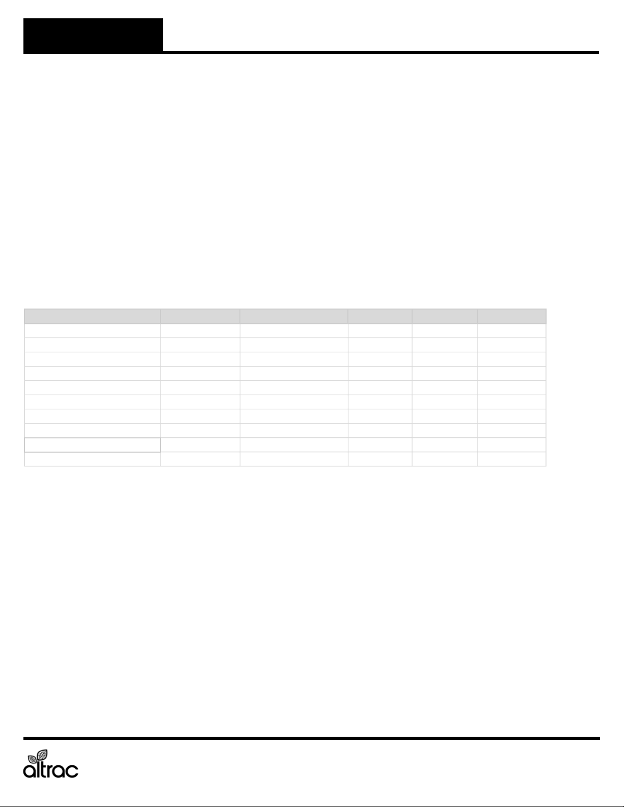
The Altrac station has the ability to check its own operation continuously. If a fault occurs, an error code will display
in the webapp. Please identify the code displayed when inquiring about service.
Altrac strives to make issues fixable by anyone. However, some of the checks below may need to be
completed by a qualified service technician. Call a service technician if you have any doubt or
reservation about performing the remedy yourself.
Error Fault Remedy
01 Altrac station not receiving power. Check the power supply and wiring to the Power Terminal.
02 Altrac is not connected to the cloud. Check that the Altrac has power.
Check signal strength and quality for the device is sufficient.
Check antenna cables are connected correctly to the circuit board.
Move the device to gain better cellular reception.
Add an external antenna for better cellular reception.
10 Relay 1 is not operating correctly.
Equipment should be ON.
Check Relay 1 status LED lights up during use.
Flip physical switch above Relay 1 and check for lit LED.
Check wiring between Relay 1 terminal and VFD or contactors.
15 Relay 2 is not operating correctly.
Equipment should be ON.
Check Relay 2 status LED lights up during use.
Flip physical switch above Relay 2 and check for lit LED.
Check wiring between Relay 2 terminal and VFD or contactors.
20 Relay 1 Feedback Not Received.
Primary Pump should be ON.
Check Relay 1 Feedback LED is ON when equipment is ON.
Check wiring between Relay 1 Feedback and VFD or current switch.
Check current switch (if applicable) is dialed in correctly.
Check VFD/Soft Start is programmed to close Run Signal relay when running.
21 Relay 1 Feedback is under minimum
current.
Check Relay 1 Feedback LED is ON when sensor is installed.
Check wiring between Relay 1 Feedback and sensor.
Check calibration in the app matches sensor specifications.
22 Relay 1 Feedback is over maximum
current.
Check Relay 1 Feedback LED is ON when sensor is installed.
Check wiring between Relay 1 Feedback and sensor.
Check calibration in the app matches sensor specifications.
23 Relay 1 Feedback is over maximum
voltage.
Check Relay 1 Feedback LED is ON when sensor is installed.
Check wiring between Relay 1 Feedback and sensor.
Check calibration in the app matches sensor specifications.
30 Relay 2 Feedback Not Received.
Secondary Pump should be ON.
Check Relay 2 Feedback LED is ON when equipment is ON.
Check wiring between Relay 2 Feedback and VFD or current switch.
Check current switch (if applicable) is dialed in correctly.
Check VFD/Soft Start is programmed to close Run Signal relay when running.
31 Relay 2 Feedback is under minimum
current.
Check Relay 2 Feedback LED is ON when sensor is installed.
Check wiring between Relay 2 Feedback and VFD or current switch.
Check calibration in the app matches sensor specifications.
32 Relay 2 Feedback is over maximum
current.
Check Relay 2 Feedback LED is ON when sensor is installed.
Check wiring between Relay 2 Feedback and VFD or current switch.
Check calibration in the app matches sensor specifications.
33 Relay 2 Feedback is over maximum
voltage.
Check Relay 2 Feedback LED is ON when sensor is installed.
Check wiring between Relay 2 Feedback and VFD or current switch.
Check calibration in the app matches sensor specifications.
40 Analog Sensor 1 is under minimum
current.
Check Analog Sensor 1 LED is ON when sensor is installed.
Check wiring between Analog Sensor 1 and sensor.
Check calibration in the app matches sensor specifications.
41 Analog Sensor 1 is over maximum
current.
Check Analog Sensor 1 LED is ON when sensor is installed.
Check wiring between Analog Sensor 1 and sensor.
Check calibration in the app matches sensor specifications.
42 Analog Sensor 1 is over maximum
voltage.
Check Analog Sensor 1 LED is ON when sensor is installed.
Check wiring between Analog Sensor 1 and sensor.
Check calibration in the app matches sensor specifications.
50 Analog Sensor 2 (Accessory Port) is
under minimum current.
Check Analog Sensor 2 (Accessory Port) LED is ON when sensor is installed.
Check wiring between Analog Sensor 2 (Accessory Port) and sensor.
Check calibration in the app matches sensor specifications.
51 Analog Sensor 2 (Accessory Port) is
over maximum current.
Check Analog Sensor 2 (Accessory Port) LED is ON when sensor is installed.
Check wiring between Analog Sensor 2 (Accessory Port) and sensor.
Check calibration in the app matches sensor specifications.
52 Analog Sensor 2 (Accessory Port) is
over maximum voltage.
Check Analog Sensor 2 (Accessory Port) LED is ON when sensor is installed.
Check wiring between Analog Sensor 2 (Accessory Port) and sensor.
Check calibration in the app matches sensor specifications.
70 Switch is in OFF position and pump
is scheduled to be ON.
Check that the HOA swich on the pump station is in the Auto position.
Check wiring between Digital Input 1 and the HOA switch.
ST140 v2.0 Remote Control and Automation for Pumps