WOERNER GMK-A User manual

Operation manual GMK-A Page 1 of 35 B0887
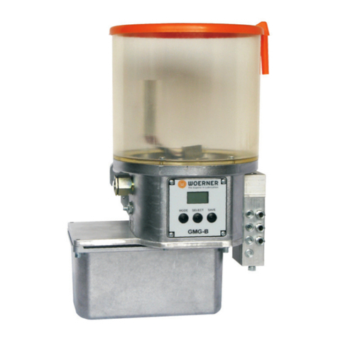
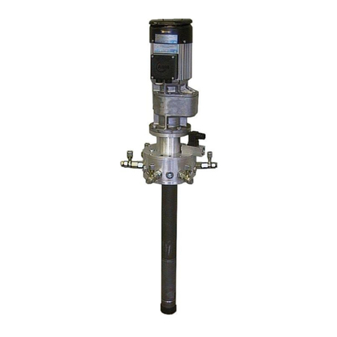
Piston pump
GMK-A
Translation of the
original operation manual
Version EN 05/2019

Operation manual GMK-A Page 2 of 35 B0887
Translation
When delivery is made into EEC countries, this operation manual
needs to be translated into the user’s country language accordingly.
In case that any inconsistency in the translated text occurs, the
original (German) operation manual should be referred to for clarifi-
cation or the manufacturer contacted.
Copyright
Unless permitted explicitly, the dissemination, reproduction, and
utilisation of this document as well as the communication of its con-
tents are prohibited. Any violation of this stipulation shall involve the
obligation to compensate damage.
All rights reserved.

Operation manual GMK-A Page 3 of 35 B0887
Table of Contents
1. Important notes on this operation manual ..................................................................5
1.1 Users......................................................................................................................5
1.2 Obligation to read...................................................................................................5
1.3 What to do in case of questions..............................................................................5
1.4 Operation manual...................................................................................................5
1.4.1 Applicability............................................................................................................5
1.4.2 Content and purpose..............................................................................................5
1.4.3 Location .................................................................................................................6
1.4.4 Meanings of safety notes and safety symbols ........................................................6
2. Identification..................................................................................................................7
2.1 Product brand and type designation.......................................................................7
2.2Product version ......................................................................................................7
2.3 Product marking.....................................................................................................7
2.4 Manufacturer and contact address .........................................................................7
2.5 Conformity..............................................................................................................7
3. Product description.......................................................................................................8
3.1 Purpose of use.......................................................................................................8
3.2 Limits of use...........................................................................................................8
3.3 Ambient conditions.................................................................................................8
3.4 Conventional usage................................................................................................9
3.5 Technical data........................................................................................................9
3.5.1 Assemblies.............................................................................................................9
3.5.2 Dimensions ..........................................................................................................10
3.5.3 Technical data......................................................................................................12
4. Functional description................................................................................................14
4.1 Drive.....................................................................................................................14
4.2 Operation .............................................................................................................14
4.3 Functional check ..................................................................................................15
4.4 Level control.........................................................................................................15
5. Safety notes.................................................................................................................16
5.1 Basic principle......................................................................................................16
5.2 Requirements on user training..............................................................................16
5.3 Safety facilities .....................................................................................................16
5.4 Accident prevention..............................................................................................17
5.5 Residual risks.......................................................................................................17
5.6 Incorrect applications ...........................................................................................17
5.7 General safety regulations and duties ..................................................................17
5.8 Disclaimer ............................................................................................................18
6. Transportation, installation, commissioning and shutdown transport ...................19
6.1 Transportation......................................................................................................19
6.2 Unpacking............................................................................................................19
6.3 Installation............................................................................................................19
6.4 Power supply and switch-on.................................................................................20
6.5 Commissioning.....................................................................................................20
6.5.1 Proposed technical modifications and conversions...............................................21
6.6 Shutdown.............................................................................................................28
7. Operation.....................................................................................................................29
7.1 Troubleshooting, fault remedy..............................................................................29
7.2 Refilling the reservoir............................................................................................29
7.3 Switching off.........................................................................................................29

Operation manual GMK-A Page 4 of 35 B0887
8. Cleaning, servicing, fault remedy, and repair............................................................30
8.1 Cleaning...............................................................................................................30
8.2 Servicing ..............................................................................................................30
8.3 Inspection schedule..............................................................................................31
8.4 Repair ..................................................................................................................31
8.5 Accessories..........................................................................................................31
9. Return shipment to factory.........................................................................................32
10. Disposal.......................................................................................................................34
11. Appendix......................................................................................................................34
11.1 Content of the declaration of conformity...............................................................34
11.2 Declaration of conformity......................................................................................35

Operation manual GMK-A Page 5 of 35 B0887
1. Important notes on this operation manual
This operation manual forms part of the machine and must be available
to the operation and maintenance personnel at any time.
The safety notes contained herein need to be observed.
When reselling the machine, this operation manual must be handed
over in any case as well.
In addition to this operation manual, always be careful to observe the
laws and regulations being applicable in the country of use.
1.1 Users
This operation manual is intended for technically qualified users, who have been instructed
or trained in the operation of the pump unit.
1.2 Obligation to read
As an operator and user of the pump unit, you are obliged to read and understand this opera-
tion manual and, in particular, its section "Safety regulations". It is your safety that is at stake!
Should you have any question or uncertainty, contact WOERNER, please.
1.3 What to do in case of questions
In case of questions that you cannot solve by means of this operation manual, WOERNER
will help you. In such situations it is indispensable that you provide us with a precise descrip-
tion of the problem at stake.
1.4 Operation manual
1.4.1 Applicability
This operation manual is applicable to the series versions of the GMK-A units. Should any
part thereof be related to particular versions only, special reference will be made.
1.4.2 Content and purpose
This operation manual contains the relevant information for the commissioning, operation
and maintenance of the pump unit. It is designed to help you in using the pump unit properly,
efficiently and safely.

Operation manual GMK-A Page 6 of 35 B0887
1.4.3 Location
This operation manual must always be available to the users at their places of work.
1.4.4 Meanings of safety notes and safety symbols
Safety notes
In this operation manual, the pictograms and key words for safety instructions, precautions,
and notes have the following meanings:
Danger! Any danger threatening immediately and capable of causing
serious personal injuries.
Warning! Any possibly dangerous situation capable of causing serious
personal injuries.
Caution! Any possibly dangerous situation that might cause minor per-
sonal injuries.
Caution! Warning about property damage.
Note! Any possibly harmful situation in which the product itself or an
object in its close vicinity might be damaged.
Important! Notes on application and other useful information facilitating the
proper usage of the product.
Danger! Any danger threatening immediately due to the presence of
electric current that may cause serious personal injuries.

Operation manual GMK-A Page 7 of 35 B0887
2. Identification
2.1 Product brand and type designation
Piston pump unit manufactured by Eugen Woerner GmbH & Co. KG
Product type: GMK-A
2.2 Product version
Version as of model year 2018
2.3 Product marking
The type label is located at the side of the pump body and contains information as follows:
Manufacturer
Type (e.g. GMK-A)
No. <order-number> (e.g. 612345/1)
Model year
2.4 Manufacturer and contact address
Eugen Woerner GmbH & Co. KG
Hafenstrasse 2
DE-97877 Wertheim
Phone +49 9342 803-0
Facsimile +49 9342 803-202
Net www.woerner.de
E-Mail info@woerner.de
2.5 Conformity
The pump unit is in conformity with the EC directive on machinery (2006/42/EG).
For the content of the declaration of conformity see the appendix (sub-section 11)

Operation manual GMK-A Page 8 of 35 B0887
3. Product description
3.1 Purpose of use
The unit GMK-A is designed for the delivery of lube oils as of 150 mm²/s
or for the delivery of lube greases from NLGI class 000 up to NLGI class
2 exclusively.
Different viscosity classes are possible, but this requires careful verify-
cation. Therefore, please contact WOERNER if you wish to operate the
unit with lubricants other than those described above.
3.2 Limits of use
The application area of the pump unit’s components is restricted as follows:
Temperature range: +10 … +80 °C
The device can also be used at lower temperatures, but this requires careful verification in
combination with the desired medium. Therefore, please contact WOERNER if you wish to
operate the device in a temperature range other than that described above.
The lifetime is 50,000 strokes, regardless of the number of outlets used.
Depending on the version, these limits of use may be restricted further. Such further restric-
tions are dealt with in this operation manual later on.
Besides, the unit’s area of application is determined by the medium to be delivered. Hence,
when determining the area of application, you also need to refer to the technical data sheets
for the medium to be used.
3.3 Ambient conditions
Unit operation in an aggressive atmosphere (solvent vapours, acids,
lyes, salt water mist, etc.) may cause damage to or corrosion of compo-
nents and, thus, failure of the system and endangerment due to leaking
lubricant!
Ambient temperature range
Lower temperature limit: +10 °C
Upper temperature limit: +80 °C
Relative humidity: max. 70%
Noise level: <70 dB(A)
Physical environment
In heights as of 1.000 metres above sea level, the system should be operated after consul-
tation with the manufacturer only.

Operation manual GMK-A Page 9 of 35 B0887
3.4 Conventional usage
The unit is exclusively designed for the delivery of lubricating oils or lubricating greases in
central lubrication systems. Conventional usage also includes:
the observance of the safety notes and adherence to the safety regulations contained
in this operation manual,
the adherence to the maintenance and servicing instructions given in this operation
manual.
Any usage contrary hereto or going beyond the conventional one may
cause serious personal and property damage.
The delivery of gases, liquefied gases, gases dissolved under pressure, va-
pours, and liquids the vapour pressure of which exceeds, at the permissible
maximum temperature, the normal atmospheric pressure (1013 mbar) by
more than 0,5 bar, as well as that of highly inflammable or explosive media
and foodstuff is prohibited!
Important! Please also note the safety data sheets pertaining to the ma-
terials used!
The unit is designed for the direct lubrication of up to six lubrication points via connecting
lines which are to be kept as short as possible. Use the flow dividers (see data sheet for or-
der numbers) to distribute the lubricant.
The unit is expressly not intended to supply a distribution system, especially not with main
and secondary distributors.
Due to the low flow rate, the use of the shortest possible lubricant lines is strongly recom-
mended in order to avoid ageing of the lubricant in the lines.
3.5 Technical data
3.5.1 Assemblies
The unit consists of up to two assemblies the different versions of which may vary:
Pump body with drive, functional check and level control
Reservoir

Operation manual GMK-A Page 10 of 35 B0887
3.5.2 Dimensions
Weight:
with reservoir 380, 250, 125 approx. 1,8 kg
with reservoir 40 approx. 3,5 kg
with reservoir 04, 05 approx. 3,0 kg
see also data sheet P0887

Operation manual GMK-A Page 11 of 35 B0887

Operation manual GMK-A Page 12 of 35 B0887
3.5.3 Technical data
In its basic version, the unit comprises the pump body with DC motor. The technical data of
this unit is as follows:
Unit GMK-A
Delivery volume per stroke and outlet 40 mm³
Speed approx. 6 min-1
Number of outlets 1 … 6
Medium Grease NLGI-class 000 … 2
Oil 150 … 1900 mm²/s
Temperature range +10 … +80 °C
Material Pump body Aluminium
galvanized steel
Sealings FPM / NBR
Mounting position user-defined
Protection class DIN EN 60529 IP65
Motor:
Voltage 24 VDC
Current consumption max. 0,5 A
Level control for reservoir 380, 250, 125:
Voltage 10 … 30 VUC
Switching current max. 0,25 A
Switching capacity 5 W/VA
Switching function NC contact at min
Functional check:
Voltage 10 … 30 VDC
Switching current max. 0,5 A
Switching capacity 10 W/VA
Switching function NO contact
1 signal per revolution
Electrical connection of the pump: Plug connection
M12x1, 5-pin
The filling level control of the reservoirs 40, 04 and 05 are connected separately (see also
technical data of the respective reservoir variant).
When connecting inductive or capacitive loads, the relevant suppres-
sor circuits need to be provided for! (Diode, RC element, varistor)

Operation manual GMK-A Page 13 of 35 B0887
Reservoir 380, 250, 125 with capacity 380 ml, 250 ml, 125 ml:
Medium: Grease NLGI-class 000 … 2
Oil 150 … 1900 mm²/s
Material: Polyamide
Weight: approx. 0,3 kg
Mounting position: user-defined
Reservoir 40:
for grease cartridges 400 g acc. to DIN 1284
Medium: Grease NLGI-class 0 ... 2
other NLGI-classes upon request
Material: St and Al
Seals: NBR / FPM
Weight without cartridge: approx. 2 kg
Mounting position: user-defined
Level control:
Voltage: 10 … 30 VUC
Switching current: max. 250 mA
Plug: M8x1, 3-pin
Protection type: DIN EN 60529 IP67
Switching function: NC contact at min
Connection diagram:
Reservoir 04 (Equipment for cartridges 400 g, System Lube Shuttle) /
Reservoir 05 (Equipment for cartridges 500 g, System Reiner):
(the following piston must be at least 25 mm away from the edge of the cartridge)
Medium: Grease NLGI-class 0 ... 2
other NLGI-classes upon request
Material: St, Al and PA
Seals: FPM
Weight without cartridge: approx. 1,5 kg
Mounting position: depending on cartridge version
and lubricant,
or user-defined
for cartridges: 400 or 500 g
Cartridges are not part
of the scope of delivery!
Level control:
Voltage: 10 … 30 VUC
Switching current: max. 0,5 A
Protection type: DIN EN 60529 IP67
Connection: Cable with plug
M8x1, 3-pin
Switching function: NO contact at min
Connection diagram:

Operation manual GMK-A Page 14 of 35 B0887
4. Functional description
4.1 Drive
The unit is driven by a DC motor, which is laterally screwed on the pump casing. The motor
is energised by externally switching the voltage supply. For that purpose, an external con-
troller is required.
4.2 Operation
The rotational movement of an electric motor 1is converted via a swash plate 2into a lifting
movement of the delivery pistons 3and 4. In the suction position (piston 4) the medium is
drawn in from the reservoir 5, in the pressure position (piston 3) the medium is pumped to-
wards the outlet.
At flow the medium flows through the integrated non-return valve 6to the outlet. Lubricant
lines can be connected with the optional push-in fitting 7. An empty reservoir 5can be refilled
via the grease nipple 8.

Operation manual GMK-A Page 15 of 35 B0887
4.3 Functional check
A fixed Reed contact is located in the pump housing. The rotational movement of swash
plate 2is detected by a Reed contact. A signal is emitted at each rotation. This signal can be
evaluated by an external controller.
4.4 Level control
A magnetic tape 10 in the follower piston 11 of the reservoir 5dampens an integrated reed
contact when the reservoir is empty. The signal is emitted as long as the magnetic tape is
within the detection range of the reed contact. When the reservoir is refilled, the empty signal
disappears automatically.
The empty signal is given when the follower piston is about 14 ... 16 mm above the reser-
voir bottom. This corresponds to a remaining filling quantity of the reservoir of approx.
25 ... 40 cm³.

Operation manual GMK-A Page 16 of 35 B0887
5. Safety notes
5.1 Basic principle
The unit leaves the factory in flawless condition and ensures high technical safety.
The unit is in conformity with the rules of technology and the applicable safety and health
regulations. Nevertheless, in case of incorrect operation or misuse, risks are threatening to
the:
lives and bodies of the users or third parties,
unit or other operator assets,
efficient use of the unit.
5.2 Requirements on user training
Any person getting to work on the unit must be authorised and trained for that purpose by
the operator. They must be able to recognise and avoid potential risks. This also includes
knowledge in the accident prevention regulations, first-aid measures, and local rescue facil-
ities.
The unit may be inspected, maintained and repaired by technically skilled per-
sonnel with product-specific training only.
Work on electric facilities may be performed by skilled electricians in conform-
ity with DIN VDE 1000-10 only.
5.3 Safety facilities
Mechanically, the unit is built intrinsically safe.

Operation manual GMK-A Page 17 of 35 B0887
5.4 Accident prevention
For accident prevention, take these measures:
Prevent unauthorised persons from accessing the unit.
Keep foreign persons away from the areas and places of risk.
Inform present foreign persons about residual risks repeatedly. Inform yourself about
such risks in the "Residual risks" section.
5.5 Residual risks
When using the unit properly and adhering to the maintenance and repair cycles and meas-
ures prescribed, there are no residual risks to persons and objects within the unit’s area.
5.6 Incorrect applications
Any usage contrary hereto or going beyond the conventional one may cause
serious personal and property damage.
As experience shows, possible incorrect applications include, for instance, the following:
the delivery of highly inflammable or explosive media,
the delivery of media being capable of reacting with the materials used for the unit,
the delivery of foodstuff.
5.7 General safety regulations and duties
Basically, the following safety regulations and duties are applicable to the use
of the pump unit:
The generally accepted rules for work safety need to be oserved.
Besides, the basic regulations and rules on work safety and acci-
dent prevention being applicable to the place of use have to be
followed.
When using the unit inside vehicles, the generally accepted traf-
fic law-related rules need to be observed.
The user is obliged to observe the regulations pertaining to the
use of working appliances.
The unit must be operated in flawless and clean condition only.

Operation manual GMK-A Page 18 of 35 B0887
It is prohibited to remove, modify, bridge or bypass any and all
protection, safety or monitoring facilities.
The unit may only be modified or changed in the areas and func-
tions provided for this purpose. The prescribed procedure must
be followed.
The operator should be notified of any fault or damage immedi-
ately.
For repair, no others than original spare parts may be used.
The operator is required to regularly check and maintain all pro-
tection, safety, and monitoring facilities.
After every repair, the flawless condition of the unit must be en-
sured by means of a test run.
5.8 Disclaimer
Should any damage be caused to persons, objects, the environment and/or property due to
the non-observance of this operation manual, no matter whether intentionally or unintention-
ally, WOERNER shall be held harmless thereof. Besides, all warranty claims will be rejected.
The same also applies to any and all consequential damage.

Operation manual GMK-A Page 19 of 35 B0887
6. Transportation, installation, commissioning and shutdown transport
6.1 Transportation
Transport the unit to its destination carefully and by using suitable aids.
6.2 Unpacking
Lift the unit out of its packaging carefully and put it on a stable and plane base.
Note! The unit and the components attached in accordance with the
scope of delivery may still contain residues of blue-dyed test oil.
6.3 Installation
The unit is ready for wall-mounting. It is to be secured by means of two M5 screws at the
both female threads of the pump body. The device is screwed from the rear side. For this
purpose, through holes are required on the wall surface. The mounting surface must be
sufficiently stable in order to be capable of carrying the pump unit’s weight including the
filled reservoir. Besides, it needs to be ensured that the mounting surface is vertical
and plane.
Drill scheme:
Alternatively, the optional mounting plate can be used. The mounting plate has through
holes. The plate can be attached to the pump body using the screws supplied. The pump
can then be mounted to the wall from the front of the unit using two M6 screws.
Drill scheme:

Operation manual GMK-A Page 20 of 35 B0887
6.4 Power supply and switch-on
Important! Be careful to compare the data of the local voltage supply with
that given under "Technical data".
Important! Lay the power supply cable such that it cannot be torn off inadver-
tently.
Important! Work on electric facilities may only be performed by skilled electri-
cians in conformity with DIN VDE 1000-10.
Connect the unit to the voltage supply and control.
Check the electric connections for correct installation prior to commissioning.
Caution!
Work on electric facilities implies danger to life!
The swash plate needs about 10 seconds for one rota-
tion. The resulting electrical signal follows the pattern
ton = 1 sec - toff = 9 sec.
This means that an external control can also use this
signal for an emergency shutdown in case one or more
lubricant lines are blocked.
WOERNER recommends programming the external
control as follows: If, with the unit switched on, no new
signal is transmitted at the latest 12 ... 14 seconds af-
ter the last signal of the function control, the unit
should be disconnected from the power supply.
This helps to prevent damage to the unit as a result of
an overload caused by a closed lubricant line.
6.5 Commissioning
The unit‘s functionality has been checked in the factory. Hence, it is ready for operation and
can be connected to a local voltage supply.
Important! Note the safety instructions contained in the "Power supply and
switch-on" section.
First fill lubricant and then start the pump unit, in every case
(Minimum filling level, see chapter 7.2).
If the installation position is unfavourable, lubricant must escape from all open outlets
after a maximum of 30 minutes of continuous operation.
This manual suits for next models
1
Table of contents
Other WOERNER Water Pump manuals

WOERNER
WOERNER GMG-B User manual

WOERNER
WOERNER GMV-B User manual

WOERNER
WOERNER GMV-C User manual

WOERNER
WOERNER GMG-LEZ User manual

WOERNER
WOERNER GFZ User manual

WOERNER
WOERNER GMF-S01 User manual

WOERNER
WOERNER PEK User manual

WOERNER
WOERNER GMZ-E User manual

WOERNER
WOERNER GMG-B User manual

WOERNER
WOERNER GMA User manual
Popular Water Pump manuals by other brands

Graco
Graco Dyna-Star 132220 instructions

Scheppach
Scheppach HWW1000 Translation of original instruction manual

Samoa
Samoa LARIUS GIOTTO operating instructions

Becker
Becker O 5.10 operating instructions

TapFlo
TapFlo Steinle Filter Press Pump Series Original instruction

Agora-Tec
Agora-Tec AT 001 008 003 operating instructions