Altronics T1KE3F4 User manual

T1KE3F4
4 Door Kit with Fused Outputs
Fully assembled kit includes:
- Trove1 enclosure with TLU1 backplane
- One (1) eFlow6NB - Power Supply/Charger
- One (1) ACM4 - Fused Access Power Controller
T1KE3F8
8 Door Kit with Fused Outputs
Fully assembled kit includes:
- Trove1 enclosure with TLU1 backplane
- One (1) eFlow6NB - Power Supply/Charger
- Two (2) ACM4 - Fused Access Power Controllers
T2KE33F16
16 Door Kit with Fused Outputs
Fully assembled kit includes:
- Trove2 enclosure with TLU2 backplane
- Two (2) eFlow6NB - Power Supply/Charger
- Two (2) ACM8 - Fused Access Power Controllers
T1KE3F4D
4 Door Kit with PTC Outputs
Fully assembled kit includes:
- Trove1 enclosure with TLU1 backplane
- One (1) eFlow6NB - Power Supply/Charger
- One (1) ACM4CB - PTC Access Power Controller
T1KE3F8D
8 Door Kit with PTC Outputs
Fully assembled kit includes:
- Trove1 enclosure with TLU1 backplane
- One (1) eFlow6NB - Power Supply/Charger
- Two (2) ACM4CB - PTC Access Power Controllers
T2KE33F16D
16 Door Kit with PTC Outputs
Fully assembled kit includes:
- Trove2 enclosure with TLU2 backplane
- Two (2) eFlow6NB - Power Supply/Charger
- Two (2) ACM8CB - PTC Access Power Controllers
Altronix/Kisi Kits
Models Include:
Installation Guide
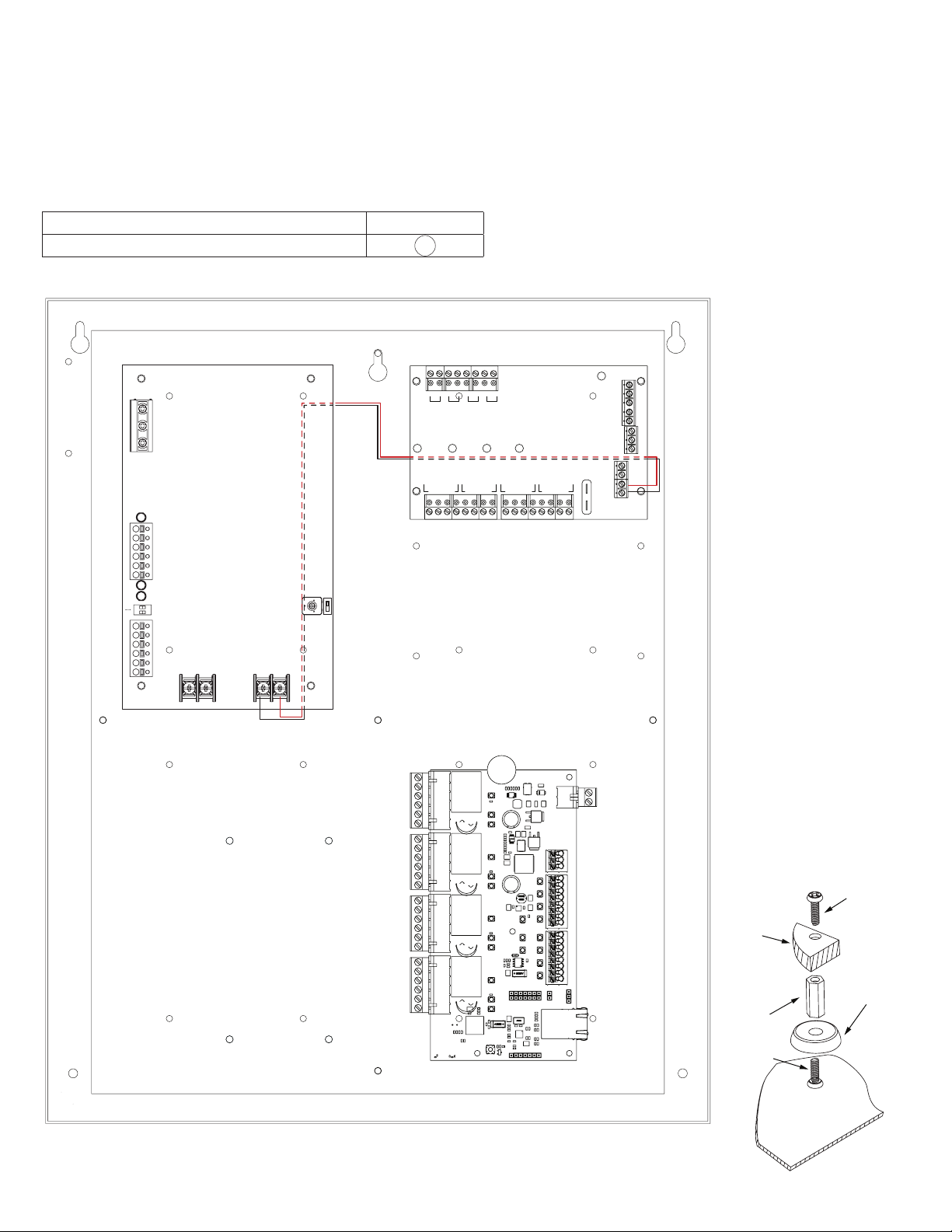
All components of these Trove kits are UL Listed sub-assemblies.
Please refer to the included corresponding Sub-Assembly Installation Guides for further information.
Access & Power Integration
Rev. 111722
Installing Company: _________________________ Service Rep. Name: __________________________________________
Address: _________________________________________________________ Phone #: _________________________
All registered trademarks are property of their respective owners. More than just power.™

- 2 - Trove KE eFlow Kits Installation Guide
Overview:
Altronix Trove Kisi kits are pre-assembled and consist of Trove1LU1 or Trove2LU2 enclosure/backplane with factory installed Altronix power
supply/charger(s) and sub-assemblies. Trove Kisi kits also accommodates up to four (4) Kisi Pro Controllers for up to sixteen (16) doors in a
single enclosure.
Configuration Chart:
Altronix
Model
Number
120VAC
60Hz
Input
Current
(A)
Power
Supply
Board
Input
Fuse
Rating
Power
Supply
Board
Battery
Fuse
Rating
Maximum Supply
Current for Main and Aux.
Outputs on Power Supply
board(s) and ACM4/ACM8
Access Power Controllers’
outputs
Nominal DC
Output Voltage
Fail-Safe/
Fail-Secure
Outputs
ACM4(CB)/
ACM8(CB)
Board
Input
Fuse
Rating
ACM4/
ACM8
Board
Output
Fuse
Rating
ACM4CB/
ACM8CB
Board
Output
PTC
Rating
[DC] [Aux]
Output
Range
(VDC)
Output
Range
(VDC)
T1KE3F4
3.5 5A/
250V
10A/
32V 24VDC @ 5.7A 20.17-
26.4
20.28-
26.4
4 10A/32V 3A/32V –
T1KE3F4D – 2.5A
T1KE3F8 8 10A/32V 3A/32V –
T1KE3F8D – 2.5A
T2KE33F16 16 10A/250V 3.5A/250V –
T2KE33F16D – 2.5A
Installation Instructions:
Wiring methods shall be in accordance with the National Electrical Code/NFPA 70/ANSI, and with all local codes and authorities having juris-
diction. Product is intended for indoor use only.
1. Remove backplane from enclosure. Do not discard hardware.
2. Mark and predrill holes in the wall to line up with the top two/three keyholes in the enclosure. Install two/three upper fasteners
and screws in the wall with the screw heads protruding. Place the enclosure’s upper keyholes over the two/three upper
screws, level and secure. Mark the position of the lower two/three holes. Remove the enclosure. Drill the lower holes and
install the two/three fasteners. Place the enclosure’s upper keyholes over the two/three upper screws. Install the two/three lower
screws and make sure to tighten all screws refer to pages 6-7.
3. Mount included UL Listed tamper switch (Altronix Model TS112 or equivalent)
in desired location, opposite hinge. Slide the tamper switch bracket onto the edge
of the enclosure, approximately 2” from the right side (Fig. 1, pg. 2).
Connect tamper switch wiring to the Access Control Panel input or the
appropriate UL Listed reporting device. To activate alarm signal
open the door of the enclosure.
4. Mount Kisi Pro Controllers to TLU1 or TLU2 backplane, refer to pages 3-5.
5. Refer to the eFlow Power Supply/Charger Installation Guide for eFlow6NB
and corresponding Sub-Assembly Installation Guides for ACM4(CB) and ACM8(CB) for
further installation instructions.
Hardware:
Fig. 1
Tamper Switch
(included)
To Access Control Panel or
UL Listed Reporting Device
Edge of
Enclosure
Enclosure
Spacer | 5/16” Pan Head Screw | Mounting Magnet

Trove KE eFlow Kits Installation Guide - 3 -
T1KE3F4 and T1KE3F4D: Configuration of Kisi Pro Controllers:
1. Fasten mounting magnets (provided) to Kisi Pro Controllers with screws and spacers (provided) using the controllers’ mounting holes
(Fig. 2, pg. 3).
2. Attach mounting magnets to TLU1 in the approximate position as shown below (Fig. 2a, pg. 3).
Note: Kisi Pro Controllers should be properly oriented.
Please make sure that they are mounted correctly, as shown in Fig. 2 below.
3. Fasten TLU1 backplane to Trove1 enclosure utilizing hardware (provided).
Access Controller Position Chart for the Following Models:
Kisi Pem Mounting
Pro Controller A
Fig. 2 - T1KE3F4(D) Configuration
TRG
TRIGGER
INPUT
ACM4
ACCESS POWER
CONTROLLER
LED1 LED2 LED3 LED4
MAIN
OUTPUT 1
NC C NO COM NC C NO COM NC C NO COM NC C NO COM
OUTPUT 2 OUTPUT 3
IN GND
1
IN GND
2
IN GND
3
IN GND
4
OUTPUT 4
-- +
CONTROL
-- +
POWER
+INP- T +RET-
INTERFACE
NO C NC
FACP
A
Altronix ACM4(CB)
Altronix
eFlow6NB
NC C NO NC C NO
AC FAIL BAT FAIL
TRIGGER
AC DCAC1
EOL NO GND
SUPERVISED RESET
+AUX-
- BAT +-DC +
L G N
OFF - 24V
ON - 12V
ON
Spacer
Backplane
Access
Controller
Pan Head
Screw
Pan Head
Screw
Mounting
Magnet
Fig. 2a

- 4 - Trove KE eFlow Kits Installation Guide
T1KE3F8 and T1KE3F8D: Configuration of Kisi Pro Controllers:
1. Fasten mounting magnets (provided) to Kisi Pro Controllers with screws and spacers (provided) using the controllers’ mounting holes
(Fig. 3, pg. 4).
2. Attach mounting magnets to TLU1 in the approximate position as shown below (Fig. 3a, pg. 4).
Note: Kisi Pro Controllers should be properly oriented.
Please make sure that they are mounted correctly, as shown in Fig. 3 below.
3. Fasten TLU1 backplane to Trove1 enclosure utilizing hardware (provided).
Access Controller Position Chart for the Following Models:
Kisi Pem Mounting
Pro Controller A
Fig. 3 - T1KE3F8(D) Configuration
Spacer
Backplane
Access
Controller
Pan Head
Screw
Pan Head
Screw
Mounting
Magnet
Fig. 3a
Altronix
eFlow6NB
TRG
TRIGGER
INPUT
ACM4
ACCESS POWER
CONTROLLER
LED1 LED2 LED3 LED4
MAIN
OUTPUT 1
NC C NO COM NC C NO COM NC C NO COM NC C NO COM
OUTPUT 2 OUTPUT 3
IN GND
1
IN GND
2
IN GND
3
IN GND
4
OUTPUT 4
-- +
CONTROL
-- +
POWER
+INP- T +RET-
INTERFACE
NO C NC
FACP
TRG
TRIGGER
INPUT
ACM4
ACCESS POWER
CONTROLLER
LED1 LED2 LED3 LED4
MAIN
OUTPUT 1
NC C NO COM NC C NO COM NC C NO COM NC C NO COM
OUTPUT 2 OUTPUT 3
IN GND
1
IN GND
2
IN GND
3
IN GND
4
OUTPUT 4
-- +
CONTROL
-- +
POWER
+INP- T +RET-
INTERFACE
NO C NC
FACP
Altronix ACM4(CB)
Altronix ACM4(CB)
AA
NC C NO NC C NO
AC FAIL BAT FAIL
TRIGGER
AC DCAC1
EOL NO GND
SUPERVISED RESET
+AUX-
- BAT +-DC +
L G N
OFF - 24V
ON - 12V
ON

Trove KE eFlow Kits Installation Guide - 5 -
T2KE33F16 and T2KE33F16D: Configuration of Kisi Pro Controllers:
1. Fasten mounting magnets (provided) to Kisi Pro Controllers with screws and spacers (provided) using the controllers’ mounting holes
(Fig. 4, pg. 5).
2. Attach mounting magnets to TLU2 in the approximate position as shown below (Fig. 4a, pg. 5).
Note: Kisi Pro Controllers should be properly oriented.
Please make sure that they are mounted correctly, as shown in Fig. 4 below.
3. Fasten TLU2 backplane to Trove2 enclosure utilizing hardware (provided).
Access Controller Position Chart for the Following Models:
Kisi Pem Mounting
Pro Controller A
Fig. 4 - T2KE33F16(D) Configuration
Spacer
Backplane
Access
Controller
Pan Head
Screw
Pan Head
Screw
Mounting
Magnet
Fig. 4a
OUTPUT 1 OUTPUT 2 OUTPUT 3 OUTPUT 4 OUTPUT 5 OUTPUT 6 OUTPUT 7 OUTPUT 8
NC C NO COM NC C NO COM NC C NO COM NC C NO COM NC C NO COM NC C NO COM NC C NO COM NC C NO COM
IN GND IN GND IN GND IN GNDIN GND IN GND IN GND IN GND
1 2 3 4 5 6 7 8
INPUT
TRIGGER
+INP- T + RET-
NO C NC
FACP INTERFACE
Power Control
- + - +
F1 F2 F3 F4 F5 F6 F7 F8
TRG
FACP
1 2 3 4
ON
1 2 3 4
ON
Altronix ACM8(CB)
Altronix ACM8(CB)
A
A
A
A
NC C NO NC C NO
AC FAIL BATFAIL
TRIGGER
AC DCAC1
EOLNOGND
SUPERVISED RESET
+AUX-
- BAT +-DC +
L G N
OFF - 24V
ON - 12V
ON
Altronix eFlow6NB
NC C NO NC C NO
AC FAIL BATFAIL
TRIGGER
AC DCAC1
EOLNOGND
SUPERVISED RESET
+AUX-
- BAT +-DC +
L G N
OFF - 24V
ON - 12V
ON
Altronix eFlow6NB

- 6 - Trove KE eFlow Kits Installation Guide
T1KE3F4(D) and T1KE3F8(D) Enclosure Dimensions (H x W x D approximate):
18” x 14.5” x 4.625” (457mm x 368mm x 118mm)
4.5” (114.3mm) 4.5” (114.3mm) 2.75”
(69.9mm)
1.115” (28.3mm)
1.36” (34.5mm)
1.25” (31.8mm) 1.25” (31.8mm)
1.5” (38.1mm)
8.5” (215.9mm)6.5” (165.1mm)
1.5” (38.1mm)
8.5” (215.9mm)6.5” (165.1mm)
4.5” (114.3mm)
13.0” (330.2mm)
0.6” (15.2mm)
14.5” (321.3mm)
1.45” (36.8mm)
7.25” (184.2mm)
1.95” (49.5mm)
1.1” (27.9mm)
0.6” (15.2mm)
0.57” (14.5mm)
18.0” (457.2mm)
1.25” (31.8mm)

Trove KE eFlow Kits Installation Guide - 7 -
T2KE33F16(D) Enclosure Dimensions (H x W x D approximate):
27.25” x 21.5” x 6.5” (692.2mm x 552.5mm x 165.1mm)
6.75” (171.5mm)8.25” (209.5mm)
8.00” (203.2mm)
2.00” (50.8mm)
2.00” (50.8mm)
1.25” (31.8mm)
1.25” (31.8mm)
5.25” (133.4mm) 5.25” (133.4mm)7.00” (177.8mm)
1.25” (31.8mm)
6.25” (158.8mm) 19.80” (502.9mm)
1.00” (25.4mm)
27” (685.8mm)
1.5”
(38.1mm)
2.00” (50.8mm) 2.00” (50.8mm)
3.5”(88.9mm) 3.5”(88.9mm)
21.50” (546.1mm)
5.25” (133.35mm) 5.25” (133.35mm)
6.25” (158.8mm)
1.25”
(31.8mm)
0.85” (21.6mm)
0.5625” (14.3mm)
2.415” (61.3mm)
0.685” (17.4mm)
1.77”
(45mm)
0.885” (22.5mm)
1.125” (28.3mm)
Knockouts
2.00” (50.8mm) 2.00” (50.8mm)

- 8 - Trove KE eFlow Kits Installation Guide
Altronix is not responsible for any typographical errors.
––––––––––––––––––––––––––––––––––––––––––––––––––––––––––––––––––––––––––––––––––––––––––––––––––––––––––––––––––––––––––––––––––––––––––––––––––––––––
140 58th Street, Brooklyn, New York 11220 USA | phone: 718-567-8181 | fax: 718-567-9056
IITrove KE eFlow Kits K17V MEMBER
Notes:
This manual suits for next models
5
Table of contents
Other Altronics Industrial Equipment manuals
Popular Industrial Equipment manuals by other brands

Siemens
Siemens SIMATIC PG 720 PII manual

Rodix
Rodix FEEDER CUBE FC-100 Plus Series Adjustments and Set Up

VALLEY CRAFT
VALLEY CRAFT F89700 instruction manual

Graziadio & C.
Graziadio & C. DV IS/ Series Assembly instructions

IEMCA
IEMCA BOSS 338 HD Manual for use and maintenance

ABB
ABB HT566060 Operation manual

Laguna Tools
Laguna Tools Smartshop II Series manual

Swegon
Swegon GOLD CX Operation & maintenance instructions

TRI tool
TRI tool BEVELMASTER 224B Operation manual

Halfen
Halfen HBB-O bi-Trapez-Box instructions

ZWAE
ZWAE NSW30 Installation and service manual

Siemens
Siemens 3VT9500-8CH30 operating instructions