ALTUS ClioAir User manual

Technology Workstation Solutions — Powered
Service
Manual
air
November 2020

Technology Workstation Solutions — Powered
2 ALTUS | 3731 Northridge Dr, NW |Suite 1 |Walker, MI 49544 |T: 888.537.1311 Iwww.altus-inc.com | AS-1584_Rev.I
Table of ContentsTable of Contents
Summary of Warnings ........................................................................................ 3
Product Introduction ........................................................................................... 4
Keyboard Platform Adjustment........................................................................... 5
Wired Keyboard & Mousing Routing Installation ................................................ 6
Clio Worksurface & LCD Monitor Support.......................................................7-8
Charging Unit...................................................................................................... 9
Power System Overview ............................................................................. 10-11
Battery & Power System Removal/Installation ............................................12-14
Circuit Breaker Overview.................................................................................. 15
Basic Troubleshooting .................................................................................16-25
air
Software Installation Note:
Make sure your cart workstation USB port is connected to the USB port on the
MPM Power unit/controller installed in your cart. Download the Powervar
MPM View install package, and save it to the workstation desktop (or other
convenient location).
To download the latest software go to: http://connectivity.powervar.com/mpm/download.asp.
Select “Install MPMView (Windows XP/Windows 7)” to download.

3 ALTUS | 3731 Northridge Dr, NW |Suite 1 |Walker, MI 49544 |T: 888.537.1311 Iwww.altus-inc.com | AS-1584_Rev.I
Summary of Warnings
Please read all parts of this guide. When set-up is complete, do not discard guide.
Please le guide in secure place for future reference.
Appropriate airow is required for this unit to operate correctly under normal and fault conditions.
Complies with requirements for US for outside the patient environment.
Only authorized personnel, experienced in servicing electrical equipment should open the power system.
DO NOT operate the power system without the covers completely installed and the connectors attached properly. The covers
provide safety from potentially dangerous voltages.
Do not connect or disconnect the system while power is applied. Do not open or in any other manner change the access to
the internal portion of the system while power is applied.
Do not allow the system to come in contact with uids. Do not operate the system if wet.
The supplied spiral cord is rated for medical use. Connecting the cord to an outlet that is not medical grade (indicated with
green dot) will not ensure grounding protection
Sipral cord, power system and cart are for INDOOR use only. DO NOT OPERATE OUTDOORS.
Inspect spiral cord before each use. DO NOT USE CORD IF DAMAGED.
The total wattage of all installed consumer devices must not exceed 150 watts.
DO NOT run spiral cord through doorways or across walls or oors.
Fully insert certied detachable spiral cord plug into outlet. DO NOT unplug by pulling on cord. For 250VA models, a type not
lighter than SJT 18AWG should be used.
DO NOT remove, bend or modify any metal prongs or pins of spiral card cord.
DO NOT use excessive force to make connections.
Keep spiral cord away from water. DO NOT PLUG CORD INTO OUTLET IF WET.
Keep children away from spiral cord.
DO NOT ALLOW CORD TO OVERHEAT.
DO NOT drive, drag or place objects over spiral cord. Do not stand or walk on spiral cord.
Breaking the seal on the battery to add water will damage the battery and could cause injury.
Battery warranty is automatically void when a fully discharged battery is left in an unused state for more than three (3)
consecutive days.
The power system is designed for power cart mounted equipment only. DO NOT connect equipment that is not mounted
on the cart into the power system outlets. DO NOT connect cart mounted equipment directly into a power source that is not
mounted to the cart. DO NOT disassemble the MPM
Technology Workstation Solutions — Powered
air
Transportation/Storage
Store this system within a
temperature range of 32˚ F - 90˚ F
(0˚ C - 32˚ C); Pressure 500 hPa to
1060 hPA; Humidity 20% RH to
95% RH non-condensing.
Lithium Iron Phosphate
(LiFe) Battery Disposal
Battery recycling is encouraged.
Dispose of in accordance with
local, state and federal laws
and regulations.
Cart Disposal
To dispose of this cart using
the local guidelines and
regulations for waste.
Please contact Altus Customer
Service for information:
1.888.527.1311
Sealed Lead Acid
Battery must be
recycled.

4 ALTUS | 3731 Northridge Dr, NW |Suite 1 |Walker, MI 49544 |T: 888.537.1311 Iwww.altus-inc.com | AS-1584_Rev.I
Product Introduction
Standard Features:
1. Height Adjustment Column
2. High Mobility 4”/100mm
Casters
3. Height Adjustment Hand Lever
4. Handle
5. Large Thermofoil
Worksurface Area
6. Keyboard Platform
7. Mousing Area
8. LCD Monitor Support
9. User Interface
10. Power System & Battery
Compartment
11. Internal Technology &
Cable Management
12. 3-Outlet Power Cord
(not shown)
13. Coiled Power Cord Holder
14. Battery Access Panel (back)
15. Up/Down Button (electric lift only)
7
9
14
6
4
3
4
5
2
1
Technology Workstation Solutions — Powered
air
12
13
13
14
10
12
13
8
16
11
15

5 ALTUS | 3731 Northridge Dr, NW |Suite 1 |Walker, MI 49544 |T: 888.537.1311 Iwww.altus-inc.com | AS-1584_Rev.I
Keyboard Platform
Adjustment Instructions
Technology Workstation Solutions — Powered
air
The keyboard platform is tilted and stored
at 90 degrees for shipping purposes only
(See Fig. A).
To use:
Place both hands on each side of the
keyboard platform and simply tilt to desired
position and slide-out for use (See Fig. B).
1
2A
B

6 ALTUS | 3731 Northridge Dr, NW |Suite 1 |Walker, MI 49544 |T: 888.537.1311 Iwww.altus-inc.com | AS-1584_Rev.I
Wired Keyboard and Mousing Routing
Installation Instructions
Technology Workstation Solutions — Powered
The keyboard platform and mouse tray are
equipped with wire managers to
keep wires in place (See Fig. A)
Keyboard and Mouse Wire Management
to inside of technology storage area
Feed both keyboard and mouse wires
through access hole, located under the
handle (See Fig. B).
Inside of technology storage area
Once cables are through hole,
pull through (See Fig. C). Auxiliary
holes (See Fig. C).
1
2
Keyboard and Mouse Wire Management
A
C
B

7 ALTUS | 3731 Northridge Dr, NW |Suite 1 |Walker, MI 49544 |T: 888.537.1311 Iwww.altus-inc.com | AS-1584_Rev.I
Technology Workstation Solutions — Powered
1
2
3
4
5
Open front surface.
Place Flat Screen Monitor Support
through the (2) holes in the rear work
surface assembly.
Attach (2) 5/16-18” Flange Hex Nuts to bolts
underneath the rear work surface assembly.
Tighten with 1/2” wrench (preferred)or dis-
posable 1/2” wrench (included).
To manage cables within the Monitor Sup-
port, remove cover from back of support.
Use a #2 Phillips Screwdriver to remove
back cover. Do not discard (4) 8 x 5/8
screws.
1
2
Internal Cable Management
Flat Screen
Monitor Support
Clio Worksurface and LCD
Monitor Support
air

8 ALTUS | 3731 Northridge Dr, NW |Suite 1 |Walker, MI 49544 |T: 888.537.1311 Iwww.altus-inc.com | AS-1584_Rev.I
Technology Workstation Solutions — Powered
Attach Monitor to VESA Plate using the
included (4) Phillips Drive Pan Head
Machine Screws.
Choose length of screw by the depth
of mounting location on back of monitor.
If too long of screw is used, damage to
monitor may occur.
Managing monitor cables:
Once monitor is attached. Adjust
monitor to its highest position.
Manage cables from monitor down
and through cable management hole.
Reinstall back cover (Make sure to
route the cables through the side
access holes in cable management
cover). Reinstall 4 screws.
6
7
8
Clio Worksurface and LCD
Monitor Support
air

Once cart is fully set up with all electronic devices, it should be plugged into a medical grade outlet.
The cart should fully charge before deploying (Note: All carts are shipped with a 30% charge. If storing
in warehouse before deploying, charge fully).
While the cart is charging, the LED on the power system
user interface will ash until the battery is 100% full.
For LiFe Batteries: Allow up to 2 hours to fully charge.
For SLA Batteries: Allow up to 5 hours to fully charge.
Testing Your Cart
To test your cart for power, the unit needs to be turned on. To do so,
press and hold the power button on the power system user interface for approximately 2 seconds.
The power system will beep and the far left LED light will turn on. At this point, all powered devices
connected to the outlet strip should receive power. Once on, the LED Keyboard light may be used.
Press to turn light on/off. The LED Keyboard light has a 5 minute timeout function just in case the
light was not turned off by the operator.
Note: Monitors, laptops and other devices will need to be manually turned on.
Software Pre-Installation/Installation Note:
To download the latest software go to: http://connectivity.powervar.com/mpm/download.asp.
Double-click the MPM View installer icon to start the install. MPM View will
automatically detect the MPM power unit attached to the PC workstation USB port.
9 ALTUS | 3731 Northridge Dr, NW |Suite 1 |Walker, MI 49544 |T: 888.537.1311 Iwww.altus-inc.com | AS-1584_Rev.I
Charging Your Cart
Technology Workstation Solutions — Powered
air

10 ALTUS | 3731 Northridge Dr, NW |Suite 1 |Walker, MI 49544 |T: 888.537.1311 Iwww.altus-inc.com | AS-1584_Rev.I
Power System Overview
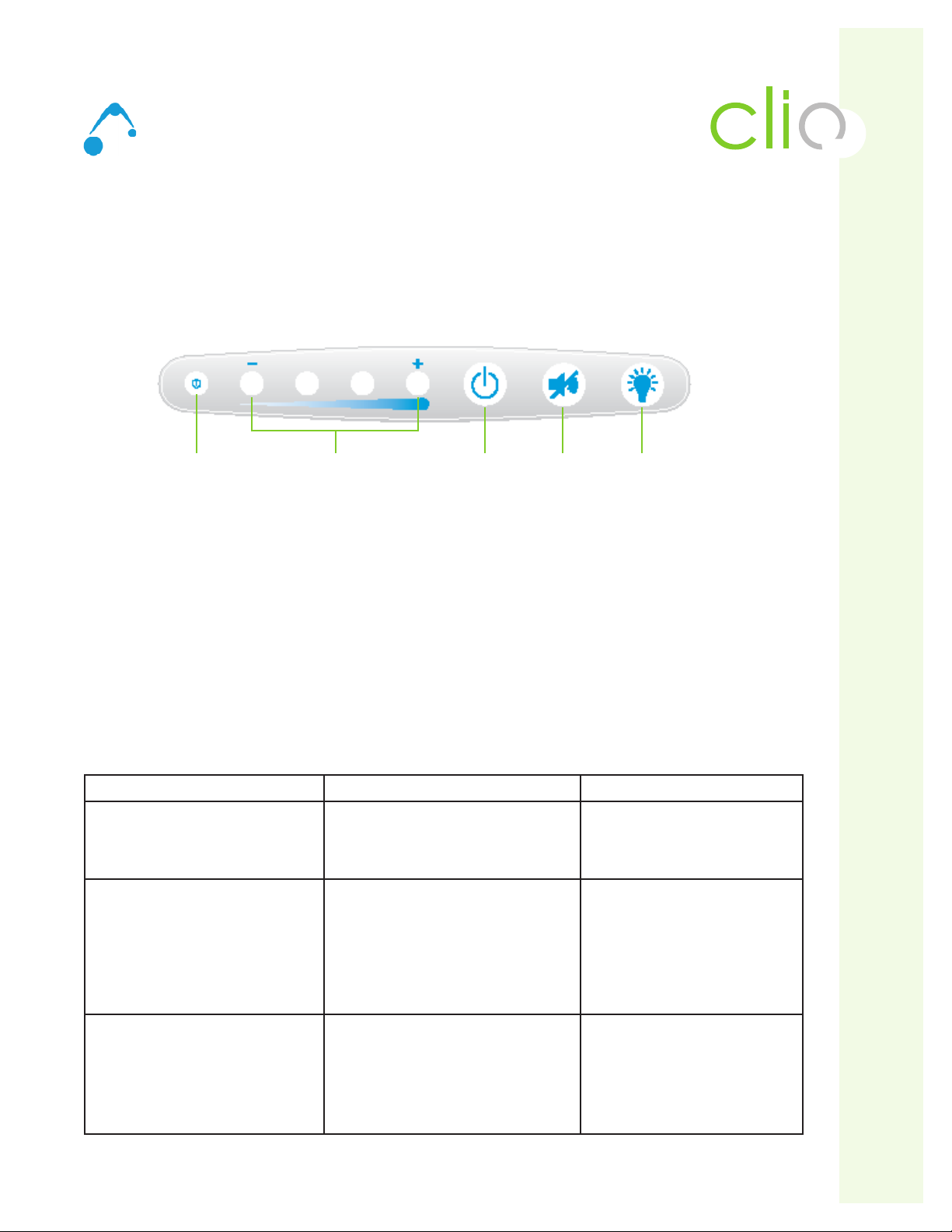
Clio External User Interface
The easy-to-read battery user interface, which is located on the front surface of the cart handle, gives the user a
real-time status of the battery. Each LED will illuminate in several sequences to indicate the approximate charge
level of the battery.
• The rst LED indicates power on/off.
• LEDs two through ve indicate charge level and correspond to a percent of charge range.
• Power Button (third to last button on right) - To power up, press and hold for 3 seconds, and the on/off
Indicator will beep and power on.
To power down, press and hold for 3 seconds, and the on/off Indicator will beep and power off.
• Power Alert Mute Button (second to last button on right) - If the battery level falls below 10% for LiFe Battery
an alarm will sound. This button will mute the alarm.
• Keyboard LED Light (last button on right) - To turn on, press button. The light will automatically turn off after
5 minutes or if button is pressed again.
Using the Power System
Turning On System Turning Off System Mute Button Use
Press and hold power button
for approximately 3 seconds
Press and hold power button
for approximately 3 seconds
Press and hold until audible alarm
discontinues
Fuel Gauge/Power System
will beep. The LED on the
left side turns green. All
components will receive power.
Fuel Gauge/Power System will beep.
LED on left side will turn off.
If Power System is plugged in, the
other LED lights will remain lit to show
battery level.
All components will NOT receive power.
Fuel Gauge/Power System will beep.
Audible alarm will silence as long as
battery level is above 10%. When
at 10%, the alarm, even if muted, will
resound every minute. Action to take
is to charge the battery or shut down
the unit.
Use this during:
• Initial start-up
• After replacing battery
• If system has been shut down
• If system has shut itself down
after reaching low battery level
Use this during:
• If cart will not be used or plugged in for
an extended period of time
• Before replacing battery
• If Power System will be serviced
Use this during:
• When the audible alarm rst goes
off at the 20% battery level
remaining. When alarm sounds,
plug in cart to avoid damage
to battery.
Technology Workstation Solutions — Powered
air
On/Off
Indicator
Battery Charge
Level
Mute
Button
Power
Button
Keyboard
LED Light

11 ALTUS | 3731 Northridge Dr, NW |Suite 1 |Walker, MI 49544 |T: 888.537.1311 Iwww.altus-inc.com | AS-1584_Rev.I
Power System Overview Continued
Technology Workstation Solutions — Powered
air
LED Position 1 (Power On/Off)
Solid Green - System is on and all components will receive power.
No Light - System is turned off. If cart is plugged in, unit can still be charged.
LED Position 2-5 (Charging Level)
Flashing Red - Less than 5% battery life remaining. Plug in unit
immediately.
Flashing Yellow - Less than 10% battery life remaining.
Plug in unit as soon as possible.
Solid Green - Battery is at least 90-100% charged. Component should
still be plugged in when possible to maximize battery life.
Flashing Green - Each LED ashing green reects the level of charge
achieved during recharging.
No Light - Power System is turned off or battery is not properly
connected to the power system.
LED Position 5 (Charging Status when plugged into wall outlet)
Solid Green - Battery is full
* Battery Low:
LED 2 Flashing Yellow ON for 1 second,
OFF for 1 second. Buzzer should beep once
per second, until silenced by pressing
“Alarm Mute button.
** Battery Low Critical
When State of Charge level falls below
6%, LED 2 will ash RED 1/2 second ON,
1/2 second OFF. Buzzer will beep 2X each
second - until silenced by pressing
“Allarm Mute” button.
***Output On LED Behavior
LED 1 is on when output is on and off
when output is off.

12 ALTUS | 3731 Northridge Dr, NW |Suite 1 |Walker, MI 49544 |T: 888.537.1311 Iwww.altus-inc.com | AS-1584_Rev.I
Battery Removal and Replacement
Only use batteries specied by ALTUS. Failure to
do so will void the power system warranty.
Call customer service for further details.
Do not replace battery in oxygen rich environments
sparking may occur.
Always unplug the power cord from the wall outlet
when removing the battery.
Battery Removal
Tools Needed: #2 Phillips Screwdriver
Step 1: Power Down System
A. Turn off any components plugged into cart
B. Turn off Power System by Holding On/Off
Button for 2 seconds
Step 2: Long-term Storage (more than 2 months)
Warning: If cart will not be used for more than
2 months, turn off the cart by holding the ON/OFF
Button. The battery will need to be recharged
every 30 days to prevent damage.
Step 3: Remove back access panel by loosening
and removing (2) screws (See Fig A).
Step 4: Remove back panel. Remove strap and slide
battery from base (See Fig. B)
Step 5: To access battery cable (to disconnect from controller)
loosen and remove (2) screws from the front panel
of base (See Fig. C)
Step 6: Disconnect battery harness from controller.
(See Fig. D)
Technology Workstation Solutions — Powered
air
Remove Strap
(Fig. B)
Disconnect Yellow
Battery Harness
(Fig. D)
(2) Screws on both sides
(Fig. C)
(Fig A)
(2) Screws
(Battery terminals)
Located in back on Ascend EL

13 ALTUS | 3731 Northridge Dr, NW |Suite 1 |Walker, MI 49544 |T: 888.537.1311 Iwww.altus-inc.com | AS-1584_Rev.I
Battery Removal and Replacement
Technology Workstation Solutions — Powered
air
Battery Removal Continued
Step 7: Disconnect “blue” RJ45 cable from controller.
(See Fig. E). If replacing with a SLA battery,
this step is not necessary.
Step 8: Replace with new battery and repeat Steps 1-7
in reverse order. Make sure all connections are
fully seated.
“Blue” RJ45 Cable
(Fig. E)

14 ALTUS | 3731 Northridge Dr, NW |Suite 1 |Walker, MI 49544 |www.altus-inc.com | AS-1584_Rev.I
Battery and Power System Removal and Replacement
DO NOT CONNECT THIS UNIT TO BATTERIES NOT SUPPLIED BY ALTUS
WITHOUT VERIFYING CONTROLLER SETUP AND OTHER OPTIONS WITH ALTUS.
WARNING!
If replacing the LiFe (Lithium Iron Phosphate) battery with a SLA battery or SLA to LiFe,
the following steps need to be completed. If the MPM software has been installed, this will help
with step #4.
1. All cables to and from controller must be connected, including the battery and its cables and connections.
Both the AC-In and AC-out connector ends include a locking feature to prevent them from pulling apart. To disconnect
pull back both “red” tabs. Note: Older models may not have this feature (red tabs) so simply disconnect.
Controller must rst be OFF (no lights on the Remote User Interface) and connected to AC power.
Perform this step only if using the MPM Software. If the MPM Software is not used, proceed to step 2.
Connect the USB cable into the technology component within the cart (or into a resident laptop with
the MPM software loaded).
2. Wait for the double yellow to appear on the interface.
3. When this happens, press and hold the mute button for 5 seconds. One “beep” will be made immediately.
Within 3-5 seconds after the initial “beep”, a second “beep” will be heard.
Keep holding down the mute button until a scrolling light sequence appears (release mute button at this time).
This will look like all of the green LED lights going lighting up in order and then back off in order. When green light
sequence is complete, the controller will show a Yellow LED and Green LED and then will shut itself off (all lights
will turn off) and then will “Reboot” itself. When controller reboots, the remote user interface will show the battery
level of the connected battery.
4. The “battery reading for conrmation” will only be available if MPM View is being utilized.
The cart is ready to be used.
Technology Workstation Solutions — Powered
air
No Lights USB

15 ALTUS | 3731 Northridge Dr, NW |Suite 1 |Walker, MI 49544 |T: 888.537.1311 Iwww.altus-inc.com | AS-1584_Rev.I
Circuit Breaker Overview
Technology Workstation Solutions — Powered
air
We’ve added a circuit breaker in our carts
that will allow them to protect themselves
from any current spikes found within the
system. These spikes would only happen
in extreme cases and the breaker can eas-
ily be reset in seconds.
A user would be able to tell that the circuit
has been tripped if the cart will no longer
raise or lower. The user can reach under-
neath the right side of the cart and press
the button in to reset the circuit. This will
return the cart to a functional electric lift
mechanism.

16 ALTUS | 3731 Northridge Dr, NW |Suite 1 |Walker, MI 49544 |T: 888.537.1311 Iwww.altus-inc.com | AS-1584_Rev.I
Troubleshooting
Technology Workstation Solutions — Powered
air

17 ALTUS | 3731 Northridge Dr, NW |Suite 1 |Walker, MI 49544 |T: 888.537.1311 Iwww.altus-inc.com | AS-1584_Rev.I
Troubleshooting
air
Technology Workstation Solutions — Powered

18 ALTUS | 3731 Northridge Dr, NW |Suite 1 |Walker, MI 49544 |T: 888.537.1311 Iwww.altus-inc.com | AS-1584_Rev.I
Troubleshooting
Technology Workstation Solutions — Powered
air

19 ALTUS | 3731 Northridge Dr, NW |Suite 1 |Walker, MI 49544 |T: 888.537.1311 Iwww.altus-inc.com | AS-1584_Rev.I
Troubleshooting
Technology Workstation Solutions — Powered
air

2o ALTUS | 3731 Northridge Dr, NW |Suite 1 |Walker, MI 49544 |T: 888.537.1311 Iwww.altus-inc.com | AS-1584_Rev.I
Troubleshooting
Technology Workstation Solutions — Powered
air
Table of contents
Other ALTUS Desktop manuals