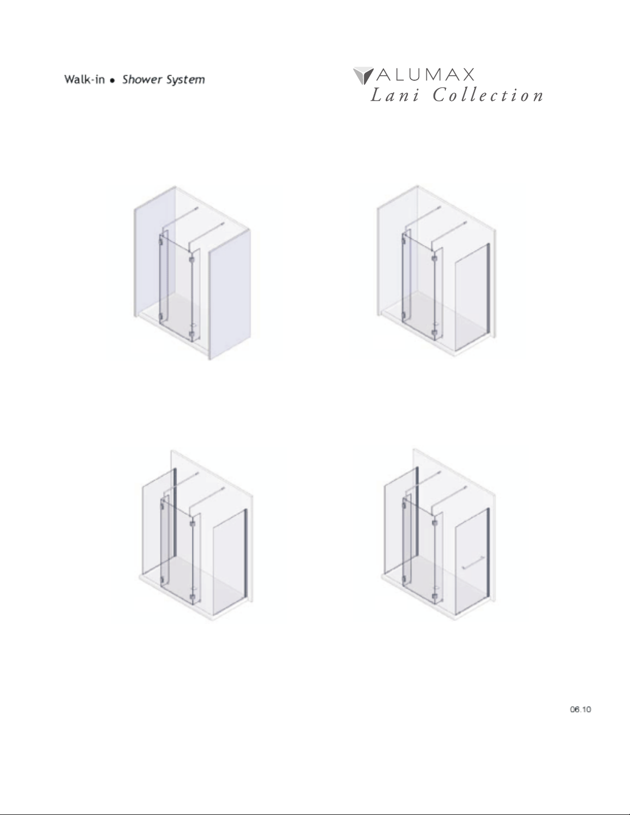
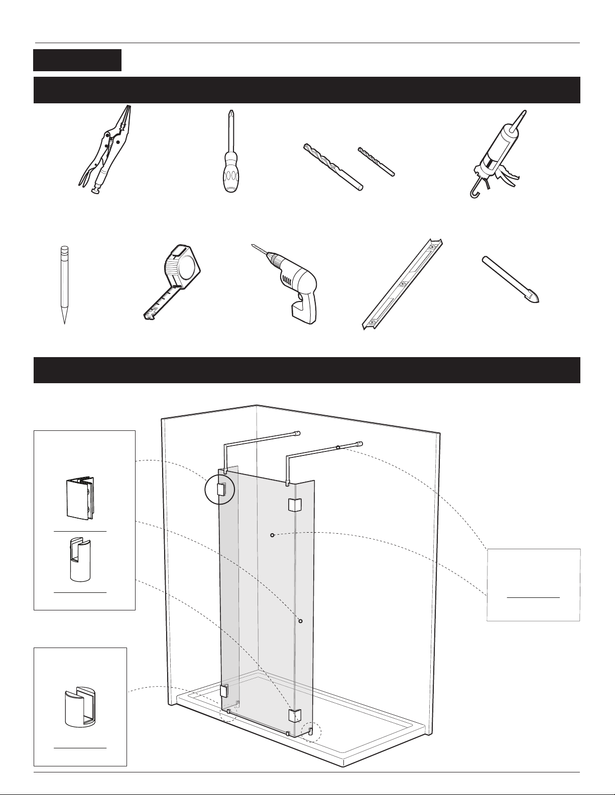
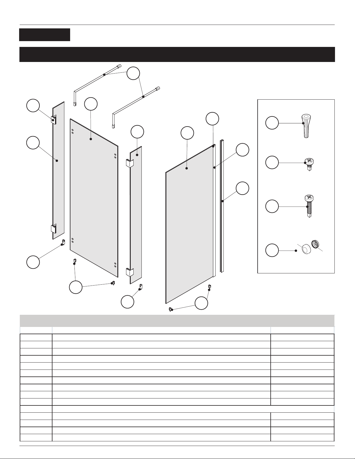
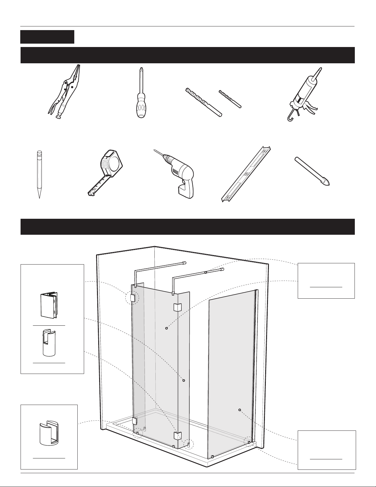
Alumax Lani L-503X-32 User manual

L003
E003
L-503X-32 L-513X-32
L-523X-32 L-523TBX-32

Please keep this manual and product code number for future reference
and replacement parts ordering if necessary.

2 PEOPLE REQUIRED
GENERAL INSTRUCTIONS
- Read this manual carefully and completely before
proceeding.
- It is recommended that you wear safety glasses at all
times during the installation.
INSTALLATION OVER CERAMIC TILES
- Silicone should be used to seal the gap where the ceramic
tiles meet the xed panel.
- If your shower door is to be installed over ceramic tiles, the
tiles should lay completely under the wall jamb.
NOTICE
- Caulking: no sealant is required inside the shower.
Unless otherwise stated.
- Some models are equipped with clear sealing gaskets.
CARE FOR YOUR SHOWER DOOR
- Never use scouring powder pads or sharp instruments on
metal pieces or glass panels.
An occasional wiping down with a mild soap diluted in
water is all that is needed to keep the panels and
aluminum parts looking new.
- We recommend wiping the glass panels with a squeegee
after each use.
Product specications are subject to change
without notice.

4
3
6
1
2
2
5
6
503X-32
PARTS LISTING
GUIDE D’INSTALLATION |INSTRUCTION MANUAL
1
I T E M # P A R T S Q T Y
1 F I X E D P A N E L 1
2S M A L L R E T U R N P A N E L 2
3 S U P P O R T B A R 2
4C O R N E R C L I P 4
5 B O T T O M C L I P 2
6 L O N G B O T T O M C L I P 2

INSTRUCTION MANUAL
TOOLS AND MATERIALS REQUIRED
INSTALLATION OF COMPONENTS
2
see page 10
see page 9
see page 12
Front panel
Support bar
Small xed panel
Corner clips
Long bottom clips
Bottom clips
PENCIL DRILL
SILICONESCREWDRIVERS
LEVELTAPE MESURE
LONG NOSE LOCKING PLIER
1/4”
1/8”
ACRYLIC DRILL BIT
1/4”
CERAMIC TILE DRILL BIT
503X-32

PARTS LISTING
INSTRUCTION MANUAL
4
2
7
5
8.1
3
8.2
1
2
5
6
6
8.3
3
b
a
WALL PLUG #6-1
SCREW CAP
11.1
11.4
SCREW #8-3/8
11.2
SCREW #8-1 1/4
11.3
HARDWARE
I T E M # P A R T S Q T Y
1F I X E D P A N E L 1
2S M A L L R E T U R N P A N E L 2
3S U P P O R T B A R 2
4 C O R N E R C L I P 4
5 B O T T O M C L I P 4
6L O N G B O T T O M C L I P 2
7W A L L J A M B 1
8 . 1 E X P A N D E R 1
8 . 2 R E T U R N P A N E L 1
8 . 3 G A S K E T 1
1 1
1 1 . 1 W A L L P L U G # 6 - 1 4
1 1 . 2 S E L F D R I I L L I N G S C R E W # 8 - 3 / 8 3
1 1 . 3 S E L F D R I L L I N G S C R E W # 8 - 1 1 / 4 3
1 1 . 4 S C R E W C A P # 8 / 8 4
H A R D W A R E
513X-32

INSTRUCTION MANUAL
TOOLS AND MATERIALS REQUIRED
4
see page 10
see page 9
see page 12
see page 14
Front panel
Support bar
Return panel panel
Bottom clips
Small xed panel
Corner clips
Long bottom clips
Bottom clips
PENCIL DRILL
SILICONESCREWDRIVERS
LEVELTAPE MESURE
LONG NOSE LOCKING PLIER
1/4”
1/8”
ACR YLIC DRILL BIT
1/4”
CERAMIC TILE DRILL BIT
INSTALLATION OF COMPONENTS
513X-32

PARTS LISTING
INSTRUCTION MANUAL
8.2
8.3 8.1
7
7
8.1
8.3
5
5
8.2
1
2
4
2
6
6
5
3
5
b
a
WALL PLUG #6-1
SCREW CAP
11.1
11.4
SCREW #8-3/8
11.2
SCREW #8-1 1/4
11.3
HARD WARE
I T E M # P A R T S Q T Y
1F I X E D P A N E L 1
2 S M A L L R E T U R N P A N E L 2
3S U P P O R T B A R 2
4C O R N E R C L I P 4
5 B O T T O M C L I P 6
6 L O N G B O T T O M C L I P 2
7W A L L J A M B 2
8 . 1 E X P A N D E R 2
8 . 2 R E T U R N P A N E L 2
8 . 3 G A S K E T 2
1 1
1 1 . 1 W A L L P L U G # 6 - 1 8
1 1 . 2 S E L F D R I L L I N G S C R E W # 8 - 3 / 8 6
1 1 . 3 S E L F D R I L L I N G S C R E W # 8 - 1 1 / 4 6
1 1 . 4 S C R E W C A P # 8 / 8 8
H A R D W A R E
523X-32

INSTRUCTION MANUAL
TOOLS AND MATERIALS REQUIRED
6
see page 10
see page 9
see page 12
see page 14
Front panel
Support bar
Return panel
Bottom clips
Small xed panel
Corner clips
Long bottom clips
Bottom clips
PENCIL DRILL
SILICONESCREWDRIVERS
LEVELTAPE MESURE
LONG NOSE LOCKING PLIER
1/4”
1/8”
ACRYLIC DRILL BIT
1/4”
CERAMIC TILE DRILL BIT
INSTALLATION OF COMPONENTS
523X-32

PARTS LISTING
INSTRUCTION MANUAL
9.2
7
5
9.1
3
9.3
7
1
2
2
4
6
6
5
8.2
8.1
8.3
5
10
7
b
a
WALL PLUG #6-1
SCREW CAP
11.1
11.4
SCREW #8-3/8
11.2
SCREW #8-1 1/4
11.3
HARD WARE
I T E M # P A R T S Q T Y
1 F I X E D P A N E L 1
2 S M A L L R E T U R N P A N E L 2
3 S U P P O R T B A R 2
4 C O R N E R C L I P 4
5 B O T T O M C L I P 6
6L O N G B O T T O M C L I P 2
7 W A L L J A M B 1
8 . 1 E X P A N D E R 1
8 . 2 R E T U R N P A N E L 1
8 . 3 G A S K E T 1
9 . 1 E X P A N D E R 1
9 . 2 R E T U R N P A N E L 1
9 . 3 G A S K E T 1
1 0 T O W E L B A R 1
1 1
1 1 . 1 W A L L P L U G # 6 - 1 8
1 1 . 2 S E L F D R I I L L I N G S C R E W # 8 - 3 / 8 3
1 1 . 3 S E L F D R I L L I N G S C R E W # 8 - 1 1 / 4 3
1 1 . 4 S C R E W C A P # 8 / 8 8
H A R D W A R E
523TBX-32

INSTRUCTION MANUAL
TOOLS AND MATERIALS REQUIRED
8
see page 10
see page 9
see page 12
see page 14
Front panel
Support bar
Return panel
Bottom clips
Small xed panel
Corner clips
Long bottom clips
Bottom clips
see page 16
Bar á serviette
Towel bar
PENCIL DRILL
SILICONESCREWDRIVERS
LEVELTAPE MESURE
LONG NOSE LOCKING PLIER
1/4”
1/8”
ACR YLIC DRILL BIT
1/4”
CERAMIC TILE DRILL BIT
INSTALLATION OF COMPONENTS
523TBX-32

INSTRUCTION MANUAL
BOT
503X, 513X, 523X, 523TBX
TOM CLIPS INSTALLATION
13.25”
335mm
13.25”
335mm
center of threshold
center of exposed base
1a. Using the measuring tape, mark the center
of the threshold of the base. Find the center
of the exposed base and draw a line to the
center of the threshold. The line must be
perpendicular . Place both bottom clips (5)
along the line of the center of threshold.
Mark the screw location following the
dimensions shown in the drawing.
Dimensions on the drawing are for
ABN3672 base installation.
1b.
1c. Apply
Remove the bottom clips to drill the base
using #1/8” drill bit.
silicone into the groove at the bottom
of the clip and around the hole dirlled.
Fasten the bottom clips to the base using
the provided screws. Place the gaskets into
bottom clips slots.
1
1a
1b
5
1c
9
5
CLEAR GASKET
5

INSTRUCTION MANUAL
SUPPORT BARS INSTALLATION
2a
2
2a. Take apart the end component of the
support bar with the provided Allen Key.
2b. Transfer the position of the bottom clip
(5) to the back wall. At 82” from the
threshold mark the position (center of the
cylinder A) for the support bar end
component mounting.
2c. Drill the back wall using a 1/4”drill bit.
2d. Apply a bead of silicone in each hole and
insert the wall plugs. Proceed to fasten the
wall end components onto the wall.
2e.
ø
To ease subsequent installation on the front
panel. Insert bar (3) in the component wall
(A) on a horizontal plane as shown.
Tighten the set screws.
MIN 82” | MAX. 82 1/4”
DISTANCE FROM TOP OF THRESHOLD TO CENTER OF WALL END COMPONENT
2c
2e
2d
WALL END COMPONENT
3
5
3
A
10
A
B
A
B
2b
503X, 513X, 523X, 523TBX

INSTRUCTION MANUAL
CONTINUED
2
2f.
Place the front xed panel into the bottom
clips (5) attached to the base.
2g.
Insert the clear gasket as shown. Then
Loosen and rotate support bar to grab the
front panel.
Level support bar. Tighten the set screws. 5
A
B
2f
2g
B
11
B
CLEAR GASKET
CLEAR GASKET
5
B
A
INTERIOR
SHOWER SIDE
INTERIOR
SHOWER SIDE
503X, 513X, 523X, 523TBX

3b
EDGE
3a. Temporarily install the corner clips(4) onto
the glass panels (1 & 2). Align the edge of
the small return panels onto the back face
of the front panel as shown in the detail.
Holding the glasses from the front install
corner clip front plate onto front panel slots.
Slide the corner clip until it meets the side
xed panel holes.
3b. Place the long bottom clip (6)right at the
edge of the glass (2). Mark on the base its
location.
A second person
proceeds to tighten the black plates of
corner clip from the inside of the shower.
Level the small glass panels by adjusting
the corner clips.
INSTRUCTION MANUAL
3
LONG BOTTOM CLIPS INSTALLATION
3a
FRONT PANEL
FRONT PANEL
1
2
CORNER CLIPS INSTALLATION
1
2
1
2
8
6
2
12
INTERIOR
SHOWER SIDE
503X, 513X, 523X, 523TBX

INSTRUCTION MANUAL
3
3c.
Install the provided gasket.
3d.
Remove the small xed panel by
unscrewing the corner clip back plate.
On the marked position drill the base with a
drill bit 1/8”. Put silicone onto the bottom
clip bottom face groove and around the
hole.
Fasten it to the base with screw #6-1”.
Placed inside the shower silicone seal
along the corner between the glass panels
all the way long trough out the corner clips.
3c
CONTINUED
3d
13
6
CLEAR GASKET
INTERIOR
SHOWER SIDE
INTERIOR
SHOWER SIDE
503X, 513X, 523X, 523TBX

INSTRUCTION MANUAL
4RETURN PANEL INSTALLATION
4a.
4b.
4c.
4d.
Using a measuring tape, mark the center of
the threshold of the base
Using the marking established in the
previous step, run a second line up the
wall. Use a level to ensure verticality of this
line.
Place the wall jamb (7) onto the wall while
ensuring that the wall jamb slotted holes
are centered to the center line. The side
holes of the wall jamb should face the
interior of the shower .
Drill holes using a Ø1/8 ½drill bit, through
the wall using the wall jamb slotted holes as
reference.
Insert a drop of silicone into each hole
made in the previous step. Insert a wall
plug (11.1) into each hole and from there
the wall jamb can be repositioned and
permanently fastened using self drilling
screws #8-1 1/4 (11.3).
4a
4b
4c
4d
7
7
11.1
11.3
THIS INSTALLATION PROCEDURE APPLIES FOR
ALL RETURN PANEL INSTALLATIONS
REGARDLESS QUANTITY OR ADITTIONAL
FIXTURE AS TOWEL BAR.
14
INTERIOR
SHOWER SIDE
503X, 513X, 523X, 523TBX

INSTRUCTION MANUAL
4CONTINUED
4f
4e
4 1/4"
30 3/8"
4e. Place the bottom clips (5) for return panel
on the line traced previously following
dimension shown on the plan view.
Mark the screw location.
4f.
4g.
4h.
Remove temporary the bottom clips to drill
the base using #1/8” drill bit.
Put silicone onto the bottom clip bottom
face groove and around the hole. Finally,
fasten the bottom clips to the base using
the provided screws. Place the gaskets into
bottom clips slots.
Slide the return panel assembly into the
wall jamb (7) and through the bottom clips
slots. Once the return panel has been
adjusted, secure the expander (8.1 & 9.1)
to the wall jamb (7) by way of a clamp so as
to keep the return panel level.
Fasten tightly the bottom clips set screws
(5).
Secure the wall jamb (7) to the expander
(8.1 & 9.1) by using.#8- 3/8 screws (11.2),
as well as screw caps (11.4).
5
5
5
8
9.1 7
7
11.4
11.2
5
8
15
8.1
5
503X, 513X, 523X, 523TBX

INSTRUCTION MANUAL
5TOWEL BAR INSTALLATION
5a. Install the towel bar (10) as illustrated.
5b. Silicone seal the exterior of the shower
along the wall. Fill gap between glass
panels and base surrounding the bottom
clips (8).
5b
5a
HOURS
16
10
9.2
10
523TBX
This manual suits for next models
3
Table of contents
Other Alumax Bathroom Fixture manuals
Popular Bathroom Fixture manuals by other brands

Kohler
Kohler Mira Sport Max J03G Installation and user guide

Moen
Moen 186117 Series installation guide

Hans Grohe
Hans Grohe Raindance Showerpipe 27235000 Instructions for use/assembly instructions

Signature Hardware
Signature Hardware ROUND SWIVEL BODY SPRAY 948942 Install

fine fixtures
fine fixtures AC3TH installation manual

LIXIL
LIXIL HP50 Series quick start guide