ALUNG Hemolung CR4 Installation guide

Training Workbook
Pioneered by
80450
HL-PL-0256_RB

|Page 2 |
Table of Contents
1 Introduction ...................................................................................3
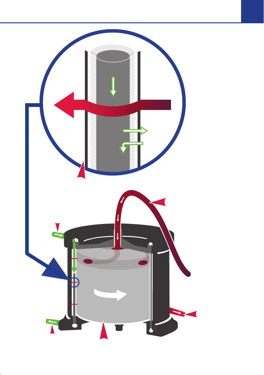
2 Theory of Operation.....................................................................4
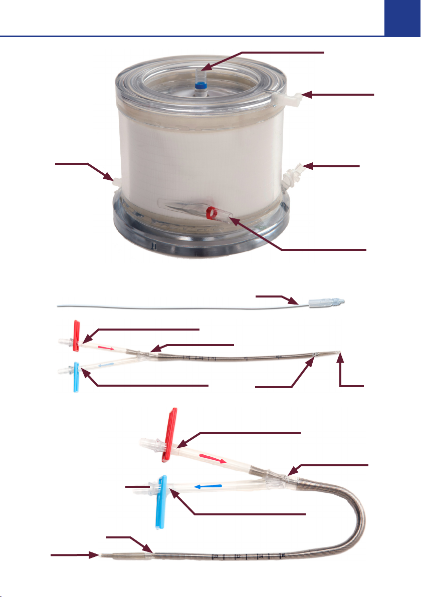
3 Hemolung RAS Components .....................................................6
4 Preparation of the Hemolung RAS .......................................... 15
Part 1 Circuit Priming............................................................16
Part 2 Catheter Insertion .....................................................27
Part 3 Connect Tubing to Catheter...................................35
Part 4 Final Checklist............................................................37
Part 5 Start Blood Pump ......................................................38
5 Managing Therapy and Using the RAS ...................................39
Controlling Pump Speed.................................................... 40
Controlling Sweep Gas Flow ..............................................41
Start/Stop Blood Pump........................................................42
Therapy Screen......................................................................43
Menu Screens ....................................................................... 44
Daily Vacuum Canister Replacement .............................. 46
Change Seal Flush Fluid.......................................................47
Clean Magnetic Fan Cover..................................................47
6 Weaning & Ending Therapy...................................................... 48
Blood Rinse Back ................................................................. 48
Without Blood Rinse Back...................................................52
7 Troubleshooting ..........................................................................53
Management of Alarms .......................................................53
Critical Errors and Accidental Termination of Therapy
.......54
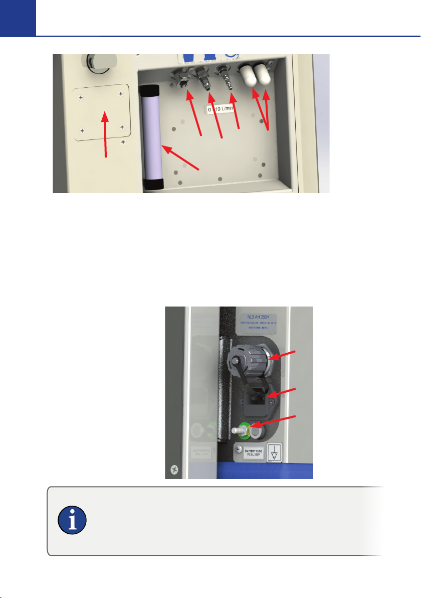
8 Device Maintenance...................................................................56
Battery .....................................................................................56
Cleaning..................................................................................56
Storage ....................................................................................57
Preventative Maintenance...................................................57
Contact Information.............................................................57

|Page 3 |
1 Introduction
The Hemolung Respiratory Assist System (RAS) is an integrated,
single-use gas exchange system designed to provide partial
extracorporeal respiratory support. Oxygen is supplied and
carbon dioxide is removed from blood circulated through the
Hemolung RAS. The utilization period of this device is validated
for up to seven days.
The intended users of the system are advanced health care
providers with experience in critical care hospital settings,
including registered nurses and physicians.
The Hemolung RAS Training Workbook contains extracts from
the Instruction for Use (IFU).
The Training Workbook is a training support tool that does not
contain safety and warning advice. It is intended as a quick
reference guide and does not replace clinical training for the
Hemolung RAS. The Workbook is not intended to be exhaustive.
In case of doubt the legal reference is always the Instruction for
Use.

|Page 4 |
2 Theory of Operation
The Hemolung RAS is an integrated, single-use gas exchange
system that provides partial extracorporeal respiratory support
by providing gas exchange independently of the lungs. Oxygen
is supplied and carbon dioxide is removed from blood circulated
through the system. This gives the patient’s lungs time to rest
and heal.
Control of CO2removal is dependent on three fundamental
factors. These are:
• Patient pCO2
• Sweep Gas Flow Rate
• Blood Flow Rate (determined by motor RPM)
CO2removal is achieved by running the selected sweep gas
(oxygen or room air) through the center of the hollow fibers in
the Cartridge while blood is circulated around the outside of the
fibers. The sweep gas flow is determined by the programmed
Sweep Gas Flow Rate and the Blood Flow Rate is determined by
the pump speed.
The dierence in CO2concentration between the patient’s
blood (high) and the sweep gas (low) causes CO2to diuse
from the blood, across the membrane, and into the sweep gas.
The CO2is then exhausted from the Hemolung Cartridge.

|Page 5 |
CO2OUT
O2
IN
BLOOD INLET
BLOOD OUTLE
T
GAS EXCHANGE MEMBRANE
SWEEP GAS OUTLET
SWEEP GAS INLET
INTE
G
RATED
C
ENTRIF
UG
AL P
U
MP
Microscopic View
of a Fiber
O2
CO2
BLOOD
Microscopic
View of a Fiber

|Page 6 |
3 Hemolung RAS Components
The Hemolung RAS is comprised of 3 main components.
Hemolung Cartridge
• Membrane oxygenator with
integrated centrifugal pump
Hemolung Catheter
• 15.5 Fr dual lumen venous
Catheter with insertion
accessories, percutaneous,
single-stick venous access,
femoral (26cm) and jugular
(17cm) available
Hemolung Controller
• Controls the Cartridge pump speed
and gas flow while providing real-
time monitoring of CO
2
removal and
blood flow, bubble detection and
other operating alarms
• Infusion pump: continuous saline
infusion to prevent bearing damage
Always check the expiration date prior to use. Do not use
the disposable if it is expired.
See Section 2 in the Instructions for Use for more Detail.

|Page 7 |
Cartridge
Catheters
Blood Inlet (BLUE)
Blood Outlet (RED)
Sweep
Gas Inlet
Seal Flush
Port with
OneWay
Valve
Sweep Gas
Outlet
Stylet
Drainage
Port
Infusion
Port
Infusion Lumen (RED)
Drainage Lumen (BLUE)
Infusion
Port
Drainage
Port
Drainage Lumen (BLUE)
Infusion Lumen (RED)
Suture Groove
Suture Groove

|Page 8 |
Hemolung Cartridge Kit Contents
Ref Product Description
13000
Hemolung Cartridge Kit - CME IV Pump Configuration
Contains all subsequent equipment used to set up
therapy
10002 Hemolung Cartridge
Membrane oxygenator with integrated centrifugal
pump
12100 Hemolung Accessories Kit - SM IV
Contains the following equipment to set up or stop
therapy:
Hemolung Rinse Back Kit
Soda Lime Column
SM IV Administration Sets
Vaseline Jelly
(7) 1500 mL Vacuum Canisters
13100 Hemolung Accessories Kit - CME IV
Contains the following equipment to set up or stop
therapy:
Hemolung Rinse Back Kit
Soda Lime Column
IV Administration Sets
Vaseline Jelly
(7) 1500 mL Vacuum Canisters
80101 Hemolung Cartridge Kit IFU
Printed Instructions for Use

|Page 9 |
Hemolung Catheter Kit Contents
Ref Product Description
30020 Hemolung 15.5 Fr Femoral Catheter Kit
(1) 15.5 Fr Femoral Catheter with Stylet
(2) Grip-Lok™ Wide Adhesive Universal Catheter
Securement
(5) 6, 9, 12, 14, & 16 Fr Dilator (1 of each)
(1) 10 mL Syringe
(1) #11 Scalpel
(1) 18 Ga x 7 cm (2.75 in) Introducer Needle
(1) 0.038 in x 100 cm Guidewire with Straightener and
J-Tip
30120 Hemolung 15.5 Fr Jugular Catheter Kit
(1) 15.5 Fr Jugular Catheter with Stylet
(2) Grip-Lok™ Wide Adhesive Universal Catheter
Securement
(5) 6, 9, 12, 14, & 16 Fr Dilator (1 of each)
(1) 10 mL Syringe
(1) #11 Scalpel
(1) 18 Ga x 7 cm (2.75 in) Introducer Needle
(1) 0.038 in x 100 cm Guidewire with Straightener and
J-Tip
Hemolung Controller
Ref Product Description
21000 Hemolung Controller - CR4
The reusable part of the Hemolung RAS. This self-
contained unit holds all electronics and monitoring
sensors.

|Page 10 |
Controller (Side)
1 Diagnostic Ports Access (Refer to CAUTION)
2 Soda Lime Column
3 Vacuum Canister Port
4 Sweep Gas Port to Hemolung Cartridge
5 O2Inlet Port
6 Air Inlet/Oxygen Exhaust Filters (Porex)
Controller (Back)
7 USB Port
8 AC Power Inlet
9 Grounding Port
The Diagnostic ports must be covered at all times during use
of the Hemolung system. Removal of the Diagnostic Port cover
may result in electrical damage (ESD). The Diagnostic Ports
have no user functionality and should only be accessed by
ALung authorized service personnel.
7
8
9
2
3456
1

|Page 11 |
Controller (Front)
10 Blood Flow Sensor
11 Bubble Detectors
12 Tubing Strain Relief
13 Alarm LED
14 Controller Power Button
15 Pump Stop Switch
16 AC Power Present
17 Magnetic Drive
18 Purge Valve
19 Vacuum Canister Bracket
20 Magnetic Fan Cover
13
10 11
12
19
15
17
18
14
16
20

|Page 12 |
Hemolung Controller Display
The display incorporates touch screen controls for interfacing with the
system.
1 Screen Lock
2 Battery Status
3 Sweep Gas Oxygen Source
4 Current Mode
5 Settings
1
34
5
2

|Page 13 |
User Interface
1
2
3
4
5
1 Display Symbol Area
Indicates the following system status:
∞ Sweep gas source
∞ AC power status
∞Battery status
2 Current Mode
Displays current operational mode (device state).
3 Alarm List
Active alarms are displayed in this area. Click any alarm listed for additional
information. The Audible Alarm Icon is also located at the bottom.
4 Main Area
Information relevant to the current operational mode and user inputs are
displayed here, such as instructions, settings, and therapy parameters.
5 Navigation Area
Use the buttons located in the navigation area to interact with the system.

|Page 14 |
Therapy Mode Interface
1
2
4
3
5
6
1 Measured CO2Removal Rate
Displays the measured CO2removal rate
2 Measured Blood Flow Rate
Displays the measured blood flow rate
3CO2Removal Rate Trending Graph
This area displays the graph for CO2removal. Default period is 8 hr but can
be cycled through 8 hr, 24 hr, 7 days, or 14 days.
4 Blood Flow Trending Graph
This area displays the graph for blood flow rate. Default period is 8 hr but can
be cycled through 8 hr, 24 hr, 7 days, or 14days.
5 Programmed Sweep Gas Flow Rate
Displays the measured sweep gas flow rate
6 Programmed Pump Speed
Displays the measured pump speed (RPM) of the Hemolung Cartridge

|Page 15 |
To Begin
Plug Controller into an AC outlet and turn
on using the power button located on the
center column of the Controller.
During the POST (Power On Self Test) noise
from the vacuum pump and Cartridge
motor can be expected as they are tested.
After successful completion the Setup screen will be displayed.
• Press the Recover
button to resume
therapy if the patient
is already catheterized
and connected to the
Cartridge.
• Press the button to
enter settings.
• Press the SETUP DEVICE button if you are setting up a new
circuit.
4 Preparation of the Hemolung RAS
The preparation of the Hemolung RAS includes 4 main parts:
Part 1 Circuit Priming
Part 2 Catheter Insertion
Part 3 Connect Tubing to Catheter
Part 4 Final Checklist
Part 5 Start Blood Pump
The following supplies are required for circuit preparation:
• One 500 mL or 1000 mL bag or bottle of priming
solution. 0.9% or 0.45% NaCl (normal saline) with 1 U/mL
heparin added is the recommended priming solution.
• One 500 mL or 1000 mL bag of normal saline for seal
flush.

|Page 16 |
Step 2 Remove Old Soda Lime
Pull the old soda lime
column out of the
Controller and remove
the reusable end caps.
Discard the old soda
lime column.
Part 1 Circuit Priming
Step 1 Follow On Screen Instructions
Follow the on screen instructions and press the NEXT button to
advance through the procedure.

|Page 17 |
Step 3 Assemble and Attach New Soda Lime Column
Remove the red
shipping plugs from
the new column.
Attach the reusable
end caps to the
column and install
the new soda lime
column on the
Controller.
Step 4 Hang the Saline for Seal Flush
Hang the container of saline
for providing the seal flush on
the Hemolung Controller. If
necessary, adjust the height of
the pole so that the bottom of
the saline container is between
15cm and 30cm (between 6
and 12 inches) above the seal
flush pump.
Step 5 Set up Seal Flush
Prime the IV
administration set for
the Infusion Pump. Load
the IV administration set
into the pump. Refer to
the Instructions for Use
that accompany the IV
administration set and
infusion pump for these
procedures.

|Page 18 |
Step 6 Prepare Priming Solution
Prepare a priming solution of
at least 500 mL and hang on
the Controller. One (1) unit
(U) heparin per milliliter (mL)
saline is recommended as the
priming solution.
Step 7 Open Disposables
Remove the sterile cover from
the tray. To remove the contents
from the tray, begin by lifting
the string at the top of the
recirculation bag to unravel
the tubing. Then remove the
Cartridge from the tray last.
Step 8 Hang Recirculation Bag and Temporarily Sit Cartridge
on Controller
Hang the recirculation
bag by the attached
string on the IV pole
so that it is below the
saline bags. Temporarily
set the Cartridge on top
of the Controller.
Other priming fluids have not been qualified for use with
the Hemolung RAS. Use only at the discretion of the
prescribing physician.
The plastic sheath surrounding the blood tubing is
provided for sterile handling. Take extra care handling the
blood tubing area surrounding the Catheter connection.

|Page 19 |
• The seal flush port should not be used for drug infusion.
• Do not place excessive force on the one-way valve and
seal flush port.
Step 9 Connect Infusion Pump and Run at 30 mL/hr
Remove the cap from the seal
flush port on the Cartridge,
then attach the check valve to
the port, and connect the IV
line. Open the clamp on the IV
administration set and start the
seal flush infusion at 30 mL/ hr.
Refer to the infusion pump IFU
for instructions on operating the pump.
Step 10 Close White Clamp
and Spike Saline
Completely close the white clamp
located near the priming spike on
the blue tubing. Spike the priming
solution with the spike line from
the recirculation bag.
Step 11 Close Blue Clamp on
Recirculation Bag
Close the blue clamp on the
recirculation bag.
The Hemolung Cartridge requires a continuous infusion
of saline (0.45% to 0.9% NaCl) at a rate of 30 mL/hr
to protect the Cartridge shaft seal. Insensible water
loss occurs through the sweep gas of up to 20 mL/hr
(depending on the sweep gas flow rate). These factors
should be taken into account when managing a patient’s
electrolyte and fluid balance.

|Page 20 |
Step 12 Prime the Cartridge
Hold the Hemolung
Cartridge upside-
down with the red
blood outlet port
facing up. Open the
white clamp located
near the priming spike.
This will start the flow
of priming solution
into the Hemolung
circuit. Walk the air
through the tubing until it is completely primed and solution
begins to enter the Cartridge.
Step 13 Fill the Cartridge
Fill the Cartridge by
keeping the red port up
and the entire Cartridge
below the saline bags.
Step 14 Remove Air
With the Cartridge in the
same position, tap the side
to remove any trapped air.
Prime the Cartridge with
at least 500 mL of priming
solution.
Take caution when handling the seal flush port. Do not
expose it to excessive force.
Table of contents
Other ALUNG Medical Equipment manuals
Popular Medical Equipment manuals by other brands

MEDAP
MEDAP FINA VAC P 350 operating instructions

VNS Therapy
VNS Therapy LivaNova Tunneler 402 Directions for use

Bioventus
Bioventus EXOGEN Quick instruction guide

AMD
AMD AMD-3700 Installation and operation manual

Leica
Leica M501 user manual

Hologic
Hologic SUPERSONIC IMAGINE AIXPLORER MultiWave Cleaning Instruction Guide