SENSIRION SDP1108 User manual

www.sensirion.com Sensirion – the sensor company
SDP1108
Low Range Differential Pressure Sensor
with fast response time
−For medical ventilators (ICU and home care)
−High sensitivity below 10 Pa to measure small volume flow (neonatal)
−Fast response time for efficient trigger function
−Unsurpassed performance thanks to CMOSens®technology
−Offset and hysteresis free
−Fully calibrated and temperature compensated
−Not sensitive to the mounting orientation and vibrations
SDP1108 Product Summary
The SDP1108 is a differential pressure sensor for air
based on the successful SDP1000/ SDP2000 sensor
from Sensirion AG. The response time of the SDP1108
has been optimized for medical ventilation applications.
Mounted in a rugged, chemically inert PPS housing the
SDP1108 differential pressure sensors feature a
unique dynamic range, zero offset and unsurpassed
long term stability. This makes it an ideal fit for
demanding yet cost sensitive OEM applications in
medical and HVAC equipment.
The SDP1108 is fully RoHS compliant.
The SDP1108 is supplied with 5.0 V and provides a
0.25…4.0 V output. Although the output of the sensor
is analog, the internal linearization and temperature
compensation is performed digitally. This results in a
superior accuracy, outstanding resolution (up to 0.05
Pa), and lowest temperature dependence.
Its leading performance is based on Sensirion’s
proprietary CMOSens®sensor technology which
combines the sensor element with amplification and
A/D conversion on one single silicon chip. The
differential pressure is measured by a thermal sensing
element. In contrast to other thermal differential
pressure sensors only a very small amount of air is
required. This leads to a reliable operation even under
harsh conditions. In comparison to membrane and
piezo-resistive based sensors the SDP1108 differential
pressure sensors show an extended measurement
range, better offset stability and improved
reproducibility even at lowest pressure ranges. In
addition the SDP1108 is robust against pressure bursts
and shows no sensitivity to the mounting orientation.
Applications
Medical applications:
•Homecare ventilation
•Intensive care ventilation (ICU)
•Other
Block Diagram
Differential
pressure
Sensor
CM OSe n s
®
SENSOR CHIP
DI G IT A L
Linearization and
Temperature
com pens at ion
A/ D con v ert er
Memory
D/ A
co nve r ter
V
DD
5.0 V
OUT
0.25 V
to 4 V
GND
Data Sheet – v1.0
www.sensirion.com v1.0 October 2008 2/6
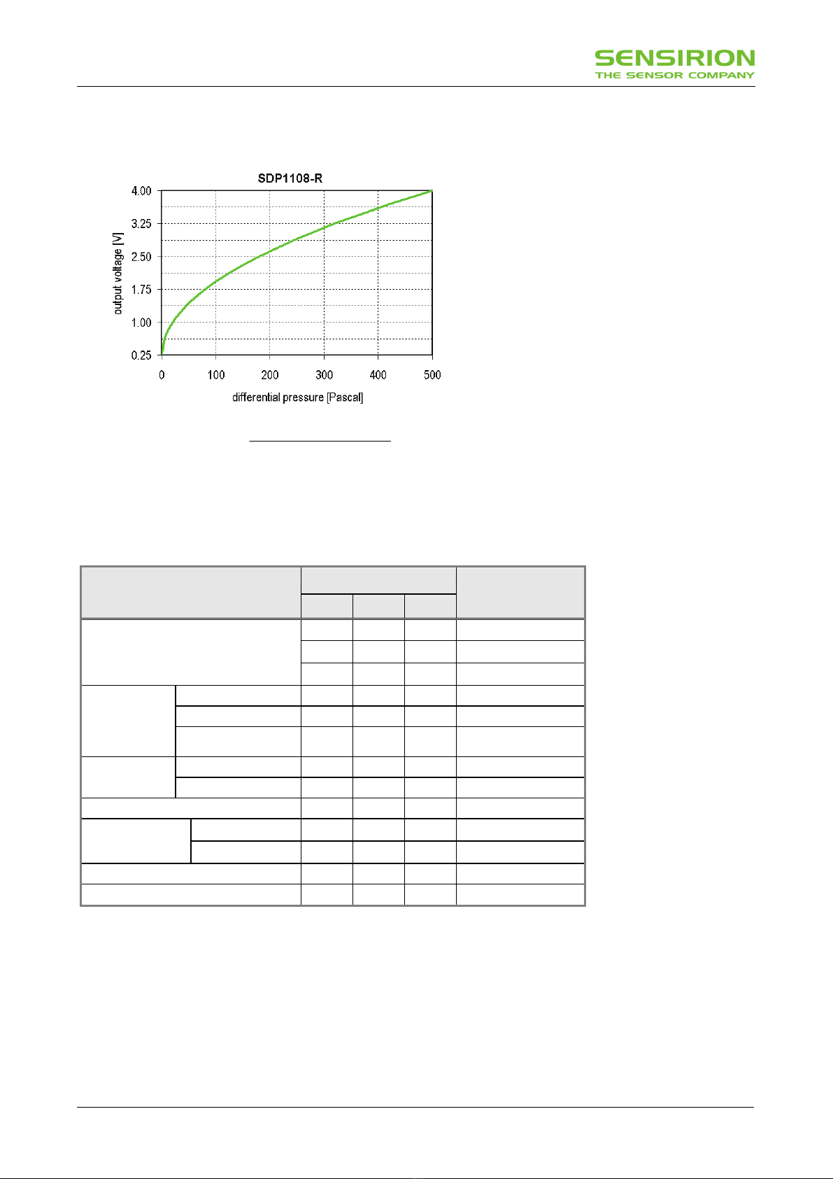
1Sensor Output Characteristics1
The SDP1108-R provides a fully calibrated
voltage output. To enhance resolution and
accuracy at very low differential pressures, the
SDP1108 standard version (SDP1108-R)
comes with a root-square output
characteristics.
For high-quantity OEM applications, other
ranges and output characteristics can be
realized. E.g. linear output and a bidirectional
measurement range is possible. Please contact
Sensirion for further information.
Pa
V.
V.Voltage_Output
]Pa[eal_PressurDifferenti 500
753
250 2
⋅
⎟
⎠
⎞
⎜
⎝
⎛−
=Use this formula to convert the sensor output
into physical value.
(1)Calibration conditions apply unless otherwise noted: 23°C and pabsolute = 966 mbar, dry air, VDD = 5.000 V
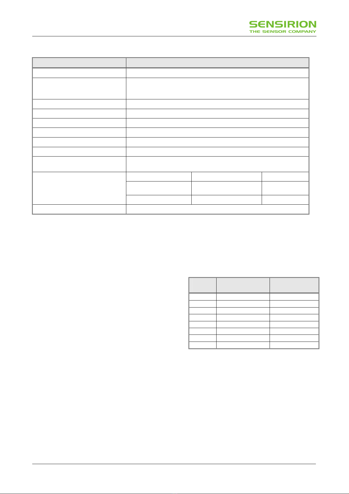
2Specifications
Table 1: SDP1108-R Sensor specifications(1)
SDP1108-R
Parameter
Min Typ Max
Unit
0.25 - 4 Volts
0 - 500 Pa
Measurement range
0 - 2 Inch water
100 to 500 Pa - 1.0 2.0 % Measured Value(4)
0 to 100 Pa - 0.2 0.4 % Full Span(5)
Accuracy(3)
zero(2) -
15
0.01
40
0.06
mV
Pa
100 to 500 Pa - 0.3 1.0 % Measured Value
Repeatability 0 to 100 Pa - 0.05 0.2 % Full Span(5)
Null drift per year(6) - 0 0.1 Pa / year
0 to 500 Pa - 0.03 0.05 % Measured Value / °C (4)
Additional error over
temperature (7)
(T ≠23°C) zero - 1 2 mV/°C
Response time(8) 6.6 8.0 10.1 Ms
Cut off frequency of internal filter 17 20 24 Hz
(1) Calibration conditions apply unless otherwise noted: 23°C and pabsolute = 966 mbar, dry air, VDD = 5.000 V
(2) Variance between the zero point (offset) of different sensors measured under the same conditions (e.g. same supply voltage, temperature, …)
(3) Include deviations due to linearity, hysteresis, and repeatability
(4) % measured value = (SDP1108 output [Pa] - output of reference instrument [Pa]) / output of reference instrument [Pa].
(5) Full span = 3750mV or 500 Pa
(6) Drift over time due to aging, pressure cycles… Test results can be provided.
(7) The additional error due to temperature variation is temporary. Once the sensor is back to the calibration temperature, the shift disappears
(no hysteresis).
(8) Tau= 0 to 63%, filter response time = 8ms. For faster response time, contact Sensirion.
www.sensirion.com v1.0 October 2008 3/6
Table 2: Additional sensor specifications.
Parameter
Media Air, N2– for other gases contact Sensirion AG.
Operating Conditions:
- Temperature
- Humidity
-10 °C … +60 °C / 14°F … 140 °F
non-condensing
Ambient storage conditions1 -40 °C … +80 °C / -40°F … 176 °F
Position sensitivity below resolution
Admissible overpressure (short term) 1 bar (14.5 PSI)
Burst Pressure Capability 2 bar (29 PSI)
Weight 14 g
Protection Class IP 20
Wetted materials Glass (silicon nitride, silicon oxide), Silicon, PPS (Polyphenylene Sulfide),
PEEK (Polyetheretherketone), FR4, Silicone as static sealing, Epoxy, Gold
EN 61000-4-2 Air discharge (ESD) ±2 kV
EN 61000-4-3 High frequency
electromagnetic radiation (HF) 3 V/m
Electromagnetic compatibility
EN 61000-4-4 Fast transients (burst) ±4 kV
Lead free ROHS compliant.
(1)For maximum 2 weeks
2.1 Temperature Compensation
The SDP1108 differential pressure sensor features a
sophisticated built-in temperature compensation circuit.
The temperature is measured on the CMOSens® chip by
means of a PTAT bandgap reference temperature
sensor. Its data is fed into a compensation circuit which
is also integrated on the CMOSens®sensor chip. No
external temperature compensation is therefore required.
2.2 Altitude Correction
The SDP1108 differential pressure transducer achieves
its unsurpassed performance by using a dynamic
measurement principle: An applied differential pressure
forces a small air flow through the SDP1108, which
measures this air flow.
The sensor signal is dependant on the ambient air
density. The temperature effect on density is
compensated by internal intelligence (see Paragraph
2.3). Effects on density due to a change of ambient
pressure, typically a change of altitude above sea level,
can be compensated using a correction factor according
to the following equation:
Dpeff = Dpsensor *Pcal / Pamb
where Dpeff is the effective differential pressure, Dpsensor
the differential pressure indicated by the SDP1108, Pcal
the absolute pressure during calibration (966 mbar)
and Pamb the actual ambient absolute pressure.
This leads to the following correction factors:
Table 3: Altitude correction factors.
Altitude
[meter]
Ambient Pressure
(Pamb) [mbar]
Correction Factor
Pcal / Pamb
0 1013 0.95
250 984 0.98
425 966 1.00
500 958 1.01
750 925 1.04
1500 842 1.15
2250 766 1.26
3000 697 1.38
Example:
The SDP1108 is used at 750 m above sea level. The
output of the SDP1108 shows 0.5 V, which
corresponds to Dpsensor = 33.3 Pa. Taking into account
the correction factor Pcal / Pamb = 1.04 the effective
differential pressure Dpeff is 33.3 Pa * 1.04 = 34.6 Pa.
Note:
In many medical and HVAC applications such as filter
monitoring, fan/ventilator control or air flow
measurement the described effect is actually
welcome since at the end the mass flow and not
volume flow is the effective value to control.
www.sensirion.com v1.0 October 2008 4/6
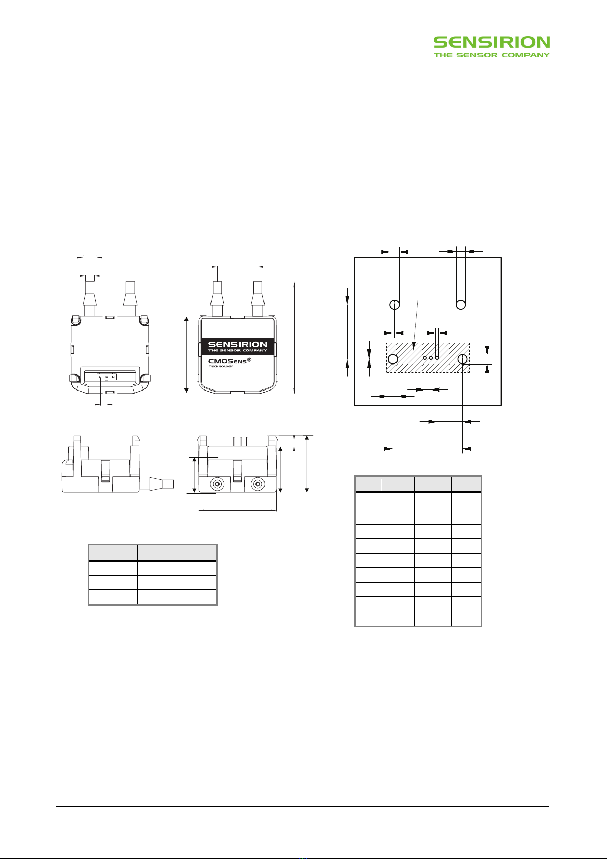
3Physical Dimensions and Mounting Information
3.1 Housing
The SDP1108 differential pressure transducer is mounted
in chemically inert PPS housing. The rugged package
has been designed to withstand continuous
overpressures of at least 1 bar (14.5 PSI). Burst pressure
is > 2 bar (29 PSI)
The physical dimensions and mounting information is
given in Figure 1 and 2.
3.4
(0.134)
5.4
(0.213)
2.54
(0.100)
16.0
(0.630)
44.0
(1.732)
SDP100000206-10033-250-001
Hi Lo
1.8
(0.071)
30.0
(1.181)
Pin#
1 2 3
A
G C
F
D
E
H
I
No Components
inside this Area
B
B
A
Figure 1: Pin out and physical dimensions in mm (inch). The
drawing is not to scale.
Figure 2: SDP1108 PCB footprint. The drawing is
not to scale.
3.2 Soldering Instructions
The SDP1108 differential pressure sensor can be wave
soldered. Direct reflow soldering is not recommended
since it may affect the accuracy.
If reflow soldering is required Sensirion recommends to
use an SMD connector (e.g. type Samtec SSM-103-L-
SV) and to mount the SDP1108 after soldering.
22.1
(0.870)
Dim.
[mm] [inch] [mil]
A 3.00 0.118 118
B 3.30 0.130 130
C 1.20 0.047 47
D 10.20 0.402 402
E 28.20 1.110 1110
F 2.54 0.100 100
G 0.60 0.024 24
H 0.50 0.020 20
I 22.70 0.894 894
Pin# Function
1 VDD
(
5
Vdc
)
2 Ground
3 OUT (0.25…4 Vdc)
18.3
(0.720)
30.5
(1.200)
5.2
(
0.205
)
13.1
(0.516)
www.sensirion.com v1.0 October 2008 5/6
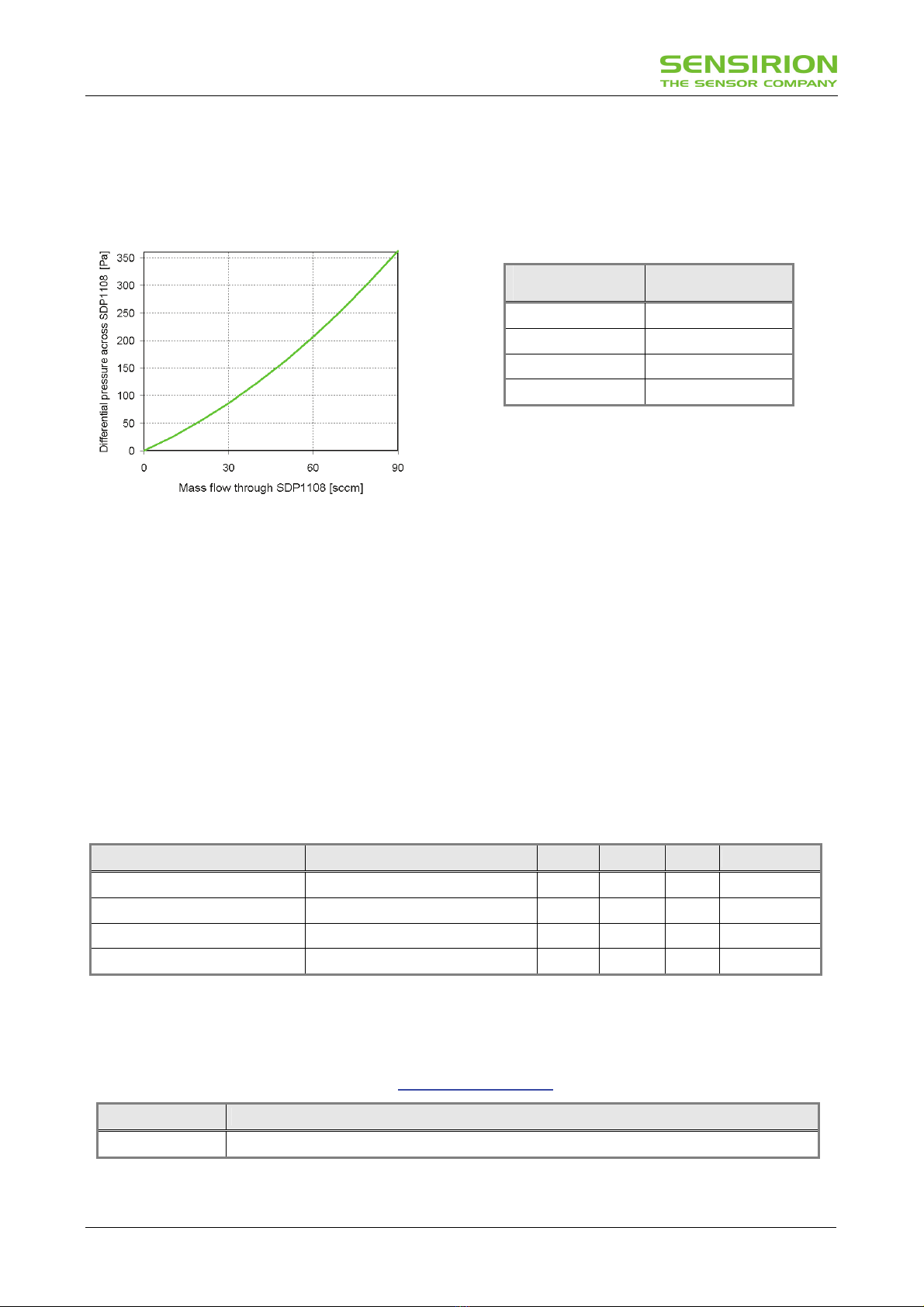
3.3 Connecting Hose
Sensirion recommends a hose with an inner diameter
of 1/8 to 3/20 inch (3.18 to 3.8mm). Due to the dynamic
measurement principle, a small air flow is required
(Figure 3) which leads to a dependence on the length
of the hose (Figure 4). Tubes up to 1 m show less than
1 % error of the measured value (Figure 4).
Figure 3: Typical air flow through the SDP1108.
Please note: 1 scc/min = 1 cm3/min at 0°C and
1013 mbar pressure (1 sccm = 0.001 norm liter).
Figure 4: Influence of the length of the connecting hose on the
accuracy (using 3/16 inch inner diameter). Example:
a 50 Pa difference pressure is shown as 49.8 Pa
when using 0.5 m tube with 3/16 inch diameter.
4Electrical Specifications
4.1 Power Supply
The SDP1108 differential pressure sensors require a
stable voltage supply of 5.0 V. Influence of the supply
voltage variation on the offset and the sensitivity are
given in Table 5.
4.2 Voltage Output
The SDP1108 features a voltage output from 0.25 V to
4.0 V. An output voltage below 0.25 V indicates a
negative differential pressure (not calibrated).
The resistive load at the output pin should be larger
than 20 kOhm. The capacitive load at the output pin
must not be larger than 200 pF. If the design shows a
larger capacity at the output pin an additional resistor is
required in series at the output (e.g. 620 Ohm).
Table 4: SDP1108 electrical characteristics.
Parameter Conditions Min. Typ. Max. Units
Power Supply Voltage VDD 4.75 5.0 5.25 VDC
Operating Current 5 V, no load, zero flow 5.1 6 mA
Output capacitive load Cload 20 200 pF
Recommended load Rload 20 100
∞kΩ
5Ordering Information
When ordering please refer to the following part names and article numbers. For the latest product information and
local distributor check out Sensirion’s website on http://www.sensirion.com
Part Name Article Number
SDP1108-R 1-100339-01
Length of the
connecting hose
Deviation of
Measured Value
0.5 m (20 inch) - 0.4 %
1.0 m (40 inch) - 0.8 %
2.0 m (80 inch) - 1.6 %
4.0 m (160 inch) - 3.2 %

www.sensirion.com v1.0 October 2008 6/6
Important Notices
Warning, personal injury
Do not use this product as safety or emergency stop devices or in any
other application where failure of the product could result in personal
injury (including death). Do not use this product for applications other
than its intended and authorized use. Before installing, handling,
using or servicing this product, please consult the data sheet and
application notes. Failure to comply with these instructions could
result in death or serious injury.
If the Buyer shall purchase or use SENSIRION products for any unintended
or unauthorized application, Buyer shall defend, indemnify and hold
harmless SENSIRION and its officers, employees, subsidiaries, affiliates
and distributors against all claims, costs, damages and expenses, and
reasonable attorney fees arising out of, directly or indirectly, any claim of
personal injury or death associated with such unintended or unauthorized
use, even if SENSIRION shall be allegedly negligent with respect to the
design or the manufacture of the product.
ESD Precautions
The inherent design of this component causes it to be sensitive to
electrostatic discharge (ESD). To prevent ESD-induced damage and/or
degradation, take customary and statutory ESD precautions when handling
this product.
See application note “ESD, Latchup and EMC” for more information.
Warranty
SENSIRION warrants solely to the original purchaser of this product for a
period of 12 months (one year) from the date of delivery that this product
shall be of the quality, material and workmanship defined in SENSIRION’s
published specifications of the product. Within such period, if proven to be
defective, SENSIRION shall repair and/or replace this product, in
SENSIRION’s discretion, free of charge to the Buyer, provided that:
• notice in writing describing the defects shall be given to SENSIRION
within fourteen (14) days after their appearance;
• such defects shall be found, to SENSIRION’s reasonable satisfaction,
to have arisen from SENSIRION’s faulty design, material, or
workmanship;
• the defective product shall be returned to SENSIRION’s factory at the
Buyer’s expense; and
• the warranty period for any repaired or replaced product shall be limited
to the unexpired portion of the original period.
This warranty does not apply to any equipment which has not been
installed and used within the specifications recommended by SENSIRION
for the intended and proper use of the equipment. EXCEPT FOR THE
WARRANTIES EXPRESSLY SET FORTH HEREIN, SENSIRION MAKES
NO WARRANTIES, EITHER EXPRESS OR IMPLIED, WITH RESPECT TO
THE PRODUCT. ANY AND ALL WARRANTIES, INCLUDING WITHOUT
LIMITATION, WARRANTIES OF MERCHANTABILITY OR FITNESS FOR
A PARTICULAR PURPOSE, ARE EXPRESSLY EXCLUDED AND
DECLINED.
SENSIRION is only liable for defects of this product arising under the
conditions of operation provided for in the data sheet and proper use of the
goods. SENSIRION explicitly disclaims all warranties, express or implied,
for any period during which the goods are operated or stored not in
accordance with the technical specifications.
SENSIRION does not assume any liability arising out of any application or
use of any product or circuit and specifically disclaims any and all liability,
including without limitation consequential or incidental damages. All
operating parameters, including without limitation recommended
parameters, must be validated for each customer’s applications by
customer’s technical experts. Recommended parameters can and do vary
in different applications.
SENSIRION reserves the right, without further notice, (i) to change the
product specifications and/or the information in this document and (ii) to
improve reliability, functions and design of this product.
Bare Die Disclaimer
All die are tested and calibrated and are guaranteed to comply with all data
sheet limits. Only random sample tests are performed on individual die.
SENSIRION has no control of third party procedures in the handling,
packing or assembly of the die. Accordingly, SENSIRION assumes no
liability for device functionality or performance of the die or systems after
third party handling, packing or assembly of the die. It is the responsibility of
the customer to test and qualify their application in which the die is used.
Copyright©2001-2008, SENSIRION.
CMOSens®is a trademark of Sensirion
All rights reserved
Revision history
Date Revision Changes
October V1.0 Initial release
Headquarters and Sales Office
SENSIRION AG Phone: + 41 (0)44 306 40 00
Laubisruetistr. 50 Fax: + 41 (0)44 306 40 30
Switzerland http://www.sensirion.com/
SENSIRION Korea Co. Ltd. Phone: +82-31-440-9925~27
#1414, Anyang Construction Tower B/D, Fax: +82-31-440-9927
Gyeonggi-Province, South Korea http://www.sensirion.co.kr
SENSIRION Inc Phone: 805-409 4900
Westlake Pl. Ctr. I, suite 240 Fax: 805-435 0467
2801 Townsgate Road michael.karst@sensirion.com
Westlake Village, CA 91361 http://www.sensirion.com/
USA
SENSIRION Japan phone: +81 3-3444-4940
Sensirion Japan Co. Ltd. fax: +81 3-3444-4939
Shinagawa Station Bldg. 7F info@sensirion.co.jp
4-23-5 Takanawa http://www.sensirion.co.jp
Minato-ku, Tokyo, Japan
Find your local representative at: http://www.sensirion.com/reps
Table of contents
Other SENSIRION Medical Equipment manuals

Popular Medical Equipment manuals by other brands


Getinge
Getinge Arjohuntleigh Nimbus 3 Professional Instructions for use

Mettler Electronics
Mettler Electronics Sonicator 730 Maintenance manual

Pressalit Care
Pressalit Care R1100 Mounting instruction

Denas MS
Denas MS DENAS-T operating manual

bort medical
bort medical ActiveColor quick guide

AccuVein
AccuVein AV400 user manual


