ALUNG HEMOLUNG RAS Installation guide

Training Workbook
HEMOLUNG
RAS
®
Pioneered by
80400
HL-PL-0036_RH

|Page 2 |
Table of Contents
1 Introduction ...................................................................................3
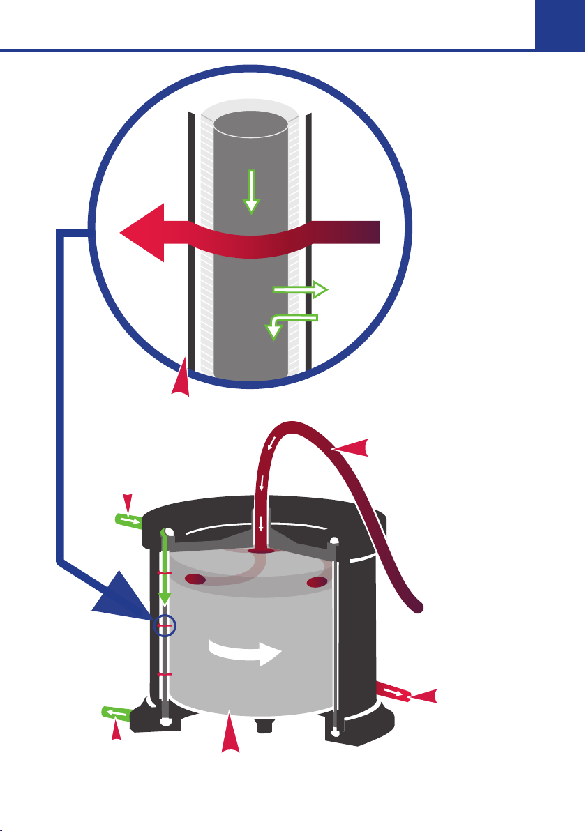
2 Theory of Operation.....................................................................4
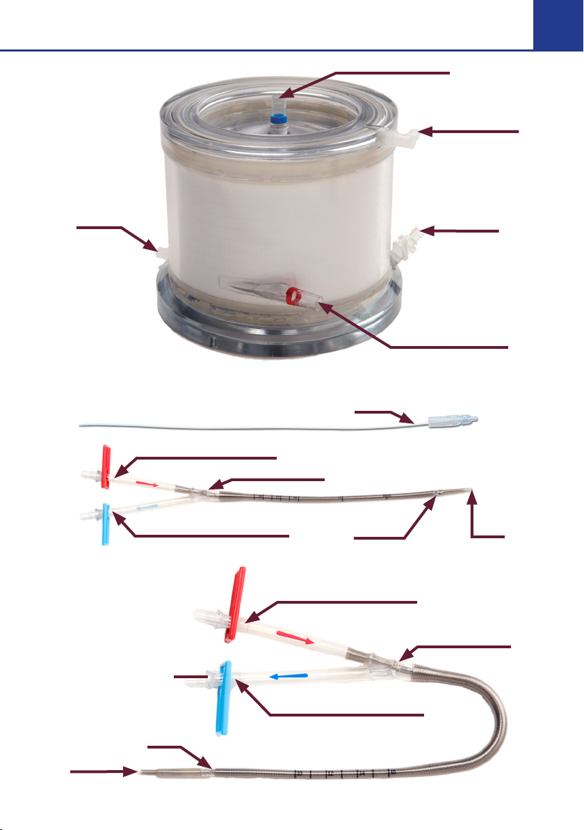
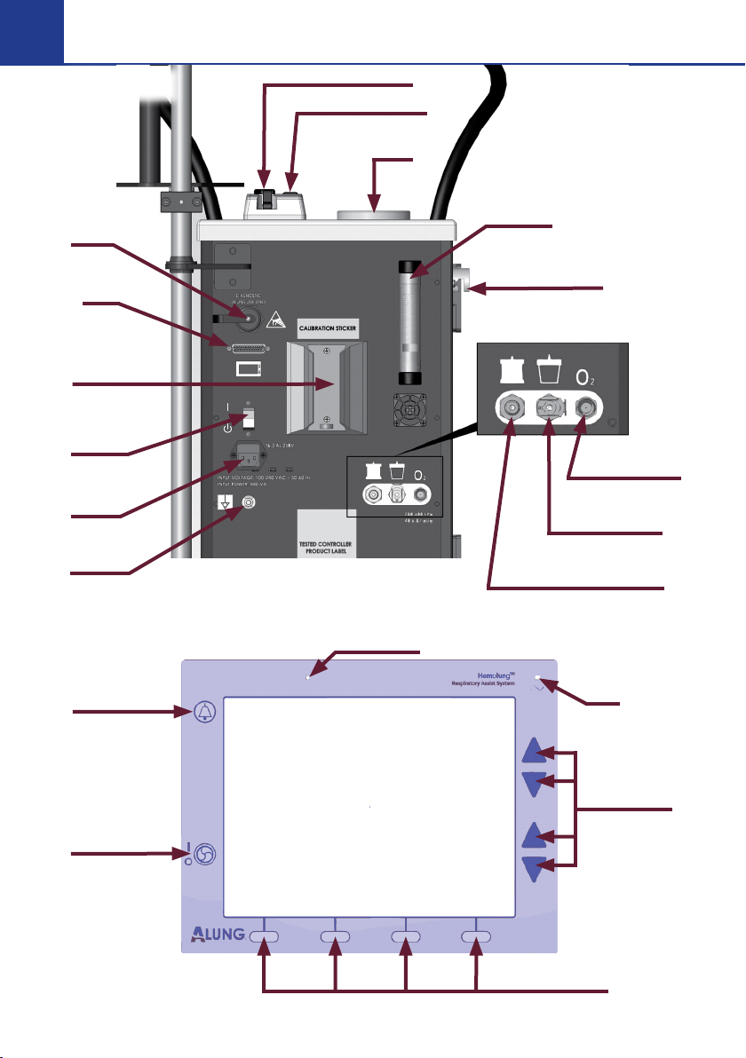
3 Hemolung RAS Components .....................................................6
4 Preparation of the Hemolung RAS .......................................... 12
Part 1 Circuit Priming............................................................ 13
Part 2 Catheter Insertion .....................................................36
Part 3 Connect Tubing to Catheter.................................. 44
Part 4 Start Blood Pump......................................................45
5 Managing Therapy and Using the RAS .................................. 46
Controlling Pump Speed.................................................... 46
Controlling Sweep Gas Flow ..............................................47
Menu Screens ........................................................................47
Daily Vacuum Canister Replacement .............................. 49
Change Sweep Gas.............................................................. 50
Change Seal Flush Fluid...................................................... 50
6 Weaning & Ending Therapy....................................................... 51
Blood Rinse Back .................................................................. 51
Without Blood Rinse Back...................................................55
7 Troubleshooting ..........................................................................56
Management of Alarms .......................................................56
Critical Errors and Accidental Termination of Therapy
.......57
8 Device Maintenance...................................................................59
Battery .....................................................................................59
Cleaning..................................................................................59
Storage ................................................................................... 60
Preventative Maintenance.................................................. 60
Contact Information............................................................ 60

|Page 3 |
1 Introduction
The Hemolung Respiratory Assist System (RAS) is an integrated,
single-use gas exchange system designed to provide partial
extracorporeal respiratory support. Oxygen is supplied and
carbon dioxide is removed from blood circulated through the
Hemolung RAS. The utilization period of this device is validated
for up to seven days.
The intended users of the system are advanced health care
providers with experience in critical care hospital settings,
including registered nurses and physicians.
The Hemolung RAS Training Workbook contains extracts from
the Instruction for Use (IFU).
The Training Workbook is a training support tool that does not
contain safety and warning advice. It is intended as a quick
reference guide and does not replace clinical training for the
Hemolung RAS. The Workbook is not intended to be exhaustive.
In case of doubt the legal reference is always the Instruction for
Use.

|Page 4 |
2 Theory of Operation
The Hemolung RAS is an integrated, single-use gas exchange
system that provides partial extracorporeal respiratory support
by providing gas exchange independently of the lungs. Oxygen
is supplied and carbon dioxide is removed from blood circulated
through the system. This gives the patient’s lungs time to rest
and heal.
Control of CO2removal is dependent on three fundamental
factors. These are:
• Patient pCO2
• Sweep Gas Flow Rate
• Blood Flow Rate (determined by motor RPM)
CO2removal is achieved by running the selected sweep gas
(oxygen or room air) through the center of the hollow fibers in
the Cartridge while blood is circulated around the outside of the
fibers. The sweep gas flow is determined by the programmed
Sweep Gas Flow Rate and the Blood Flow Rate is determined by
the pump speed.
The dierence in CO2concentration between the patient’s
blood (high) and the sweep gas (low) causes CO2to diuse
from the blood, across the membrane, and into the sweep gas.
The CO2is then exhausted from the Hemolung Cartridge.

|Page 5 |
CO2OUT
O2
IN
BLOOD INLET
BLOOD OUTLE
T
GAS EXCHANGE MEMBRANE
SWEEP GAS OUTLET
SWEEP GAS INLET
INTE
G
RATED
C
ENTRIF
UG
AL P
U
MP
Microscopic View
of a Fiber
O2
CO2
BLOOD
Microscopic
View of a Fiber

|Page 6 |
3 Hemolung RAS Components
The Hemolung RAS is comprised of 3 main components.
Hemolung Cartridge
• Membrane oxygenator with
integrated centrifugal pump
Hemolung Catheter
• 15.5 Fr dual lumen venous
Catheter with insertion
accessories, percutaneous,
single-stick venous access,
femoral (26cm) and jugular
(17cm) available
Hemolung Controller
• Controls the Cartridge pump speed
and gas flow while providing real-
time monitoring of CO
2
removal and
blood flow, bubble detection and
other operating alarms
• Infusion pump: continuous saline
infusion to prevent bearing damage
Always check the expiration date prior to use. Do not use
the disposable if it is expired.
See Section 2 in the Instructions for Use for more Detail.

|Page 7 |
Cartridge
Catheters
Blood Inlet (BLUE)
Blood Outlet (RED)
Sweep
Gas Inlet
Seal Flush
Port with
OneWay
Valve
Sweep Gas
Outlet
Stylet
Drainage
Port
Infusion
Port
Infusion Lumen (RED)
Drainage Lumen (BLUE)
Infusion
Port
Drainage
Port
Drainage Lumen (BLUE)
Infusion Lumen (RED)
Suture Groove
Suture Groove

|Page 8 |
Hemolung Cartridge Kit Contents
Product Description
Hemolung Cartridge Kit - SM IV Pump Configuration
Contains all subsequent equipment used to set up therapy
Hemolung Cartridge Kit - CME IV Pump Configuration
Contains all subsequent equipment used to set up therapy
Hemolung Cartridge
Membrane oxygenator with integrated centrifugal pump
Hemolung Accessories Kit - SM IV
Contains the following equipment to set up or stop therapy:
Hemolung Rinse Back Kit
Soda Lime Column
SM IV Administration Sets
Vaseline Jelly
(7) 1500 mL Vacuum Canisters
Hemolung Accessories Kit - CME IV
Contains the following equipment to set up or stop therapy:
Hemolung Rinse Back Kit
Soda Lime Column
IV Administration Sets
Vaseline Jelly
(7) 1500 mL Vacuum Canisters
Hemolung Cartridge Kit IFU
Printed Instructions for Use

|Page 9 |
Hemolung Catheter Kit Contents
Product Description
Hemolung 15.5 Fr Femoral Catheter Kit
(1) 15.5 Fr Femoral Catheter with Stylet
(2) Grip-Lok™ Wide Adhesive Universal Catheter Securement
(5) 6, 9, 12, 14, & 16 Fr Dilator (1 of each)
(1) 10 mL Syringe
(1) #11 Scalpel
(1) 18 Ga x 7 cm (2.75 in) Introducer Needle
(1) 0.038 in x 100 cm Guidewire with Straightener and J-Tip
Hemolung 15.5 Fr Jugular Catheter Kit
(1) 15.5 Fr Jugular Catheter with Stylet
(2) Grip-Lok™ Wide Adhesive Universal Catheter Securement
(5) 6, 9, 12, 14, & 16 Fr Dilator (1 of each)
(1) 10 mL Syringe
(1) #11 Scalpel
(1) 18 Ga x 7 cm (2.75 in) Introducer Needle
(1) 0.038 in x 100 cm Guidewire with Straightener and J-Tip
Hemolung Controller
Product Description
Hemolung Controller
The reusable part of the Hemolung RAS. This self-contained unit
holds all electronics and monitoring sensors.

|Page 10 |
Vacuum
Canister
Bracket
Diagnostic
Port
Display
Port
Controller
Power
Switch
AC Power
Inlet
Grounding
Port
Soda Lime
Column
Sweep Gas Port to
Hemolung Cartridge
Vacuum
Canister Port
O2Inlet Port
Purge Valve
Blood Flow Sensor
Bubble Detector
Magnetic
Drive
Audible
Alarm Key
Pump
Start/Stop
Key
Alarm LED
AC Power
LED
Arrow Keys
Function Keys
Controller
Hemolung Controller Display

|Page 11 |
User Interface
Therapy Mode Interface
Alarm
Notification
and Therapy
Mode Area
Display Symbol Area
Main Area
Navigation Area
Measured
CO2
Removal
Rate
Measured
Blood
Flow Rate
CO2Removal Rate Trending Graph
Blood Flow Trending Graph
Measured Sweep Gas Flow Rate
Desired/Set
Sweep Gas
Flow Rate
Measured
Pump
Speed
Desired/Set Pump Speed

|Page 12 |
To Begin
Plug Controller into an AC
outlet and turn on using the
power switch located on the
back of the Controller.
During the POST (Power
On Self Test) noise from the
vacuum pump and Cartridge
motor can be expected as
they are tested.
After successful completion the Setup screen will be displayed.
• Press the Recover button to resume therapy if the patient is
already catheterized and connected to the Cartridge.
• Press the Language button to select the language.
• Press the Continue button if you are setting up a new circuit.
This will advance you to the Select Disposables Set screen.
4 Preparation of the Hemolung RAS
The preparation of the Hemolung RAS includes 4 main parts:
Part 1 Circuit Priming
Part 2 Catheter Insertion
Part 3 Connect Tubing to Catheter
Part 4 Start Blood Pump
The following supplies are required for circuit preparation:
• One 500 mL or 1000 mL bag or bottle of priming
solution. 0.9% NaCl (normal saline) with 1 U/mL
heparin added is the recommended priming solution.
• One 500 mL or 1000 mL bag of normal saline for seal
flush.

|Page 13 |
Step 2 Remove Old Soda Lime
Pull the old soda lime
column out of the
Controller and remove
the reusable end caps.
Discard the old soda
lime column.
Part 1 Circuit Priming
Step 1 Select Disposable Set
Use the up and down
arrows to select which
disposable set you will
be using, then press the
Next button.
If using the separate
individually packaged
components, select
the top configuration. If
using the pre-connected
components within the
sealed tray, select the
bottom configuration.
Priming with
Pre-Connected Tubing

|Page 14 |
Step 3 Assemble and Attach New Soda Lime Column
Remove the red
shipping plugs from
the new column.
Attach the reusable
end caps to the
column and install
the new soda lime
column on the
Controller.
Step 4 Hang the Saline for Seal Flush
Hang the container of saline for
providing the seal flush on the
Hemolung Controller. If necessary,
adjust the height of the pole so
that the bottom of the saline
container is between 15cm and
30cm (between 6 and 12 inches)
above the seal flush pump.
Step 5 Set up Seal Flush
Prime the IV administration set
for the Infusion Pump. Load the
IV administration set into the
pump. Refer to the Instructions
for Use that accompany the IV
administration set and infusion
pump for these procedures.

|Page 15 |
Step 6 Prepare Priming Solution
Prepare a priming solution of
at least 500 mL and hang on
the Controller. One (1) unit
(U) heparin per mililiter (mL)
saline is recommended as the
priming solution.
Step 7 Open Disposables
Remove the sterile cover from
the tray. To remove the contents
from the tray, begin by lifting
the string at the top of the
recirculation bag to unravel
the tubing. Then remove the
Cartridge from the tray last.
Step 8 Hang Recirculation Bag and Sit Cartridge on Controller
Hang the recirculation
bag by the attached
string on the IV pole so
that it is below the saline
bags. Temporarily set
the Cartridge on top of
the Controller.
Other priming fluids have not been qualifed for use with
the Hemolung RAS. Use only at the discretion of the
prescribing physician.
The contents inside the tray are sterile until the lid is
removed.

|Page 16 |
The seal flush port should not be used for drug infusion.
Step 9 Connect Infusion Pump and Run at 30 mL/hr
Remove the cap from the seal
flush port on the Hemolung
Cartridge and then attach
the check valve to the port.
Open the clamp on the IV
administration set and start the
seal flush infusion at 30 mL/ hr.
Refer to the Instructions for Use
that accompany the Infusion
Pump for instructions on operating the pump.
Step 10 Close White Clamp
and Spike Saline
Close the white clamp
located near the priming
spike on the blue tubing.
Spike the priming solution
with the spike line from the
recirculation bag.
Step 11 Close Blue Clamp
on Recirculation
Bag
Close the blue clamp on the
recirculation bag.
The Hemolung Cartridge requires a continuous infusion
of saline (0.45% to 0.9% NaCl) at a rate of 30 mL/hr
to protect the Cartridge shaft seal. Insensible water
loss occurs through the sweep gas of up to 20 mL/hr
(depending on the sweep gas flow rate). These factors
should be taken into account when managing a patient’s
electrolyte and fluid balance.

|Page 17 |
Step 12 Prime the Cartridge
Hold the Hemolung
Cartridge upside-down
with the red blood outlet
port facing up. Open
the white clamp located
near the priming spike.
This will start the flow of
priming solution into the
Hemolung circuit. Walk
the air through the tubing
until it is completely primed and solution begins to enter the
Hemolung Cartridge.
Step 13 Fill the Cartridge
Fill the Cartridge by
keeping the red port up
and the entire Cartridge
below the saline bags.
Step 14 Remove Air
With the Cartridge in the
same position, tap the side
to remove any trapped air.
Prime the Cartridge with
at least 500 mL of priming
solution.

|Page 18 |
Step 15 Close the White Clamp
Once the Cartridge is full,
close the white clamp.
Step 16 Open Blue Clamp and Remove Air
Open the blue clamp
to allow any trapped air
to travel up and into the
recirculation bag. Shake the
line to assist in this process if
needed.
Step 17 Check System for Air
Visually inspect the entire
circuit for air bubbles. If air
bubbles are found in the
circuit, guide them into the
recirculation bag.

|Page 19 |
Step 18 Apply Petroleum Jelly, Install Cartridge and Tubing
Place the Cartridge on the
Controller as shown. Apply a
small amount of petroleum
jelly to the area of the tubing
that sits in the blood flow
sensor. Place the tubing into
the bubble detector and
flow sensor, and close the
flow sensor door.
Step 19 Assemble the Vacuum Canister
Place the lid on top of
the vacuum canister and
apply pressure around the
circumference of the lid to
secure it. Several "clicks" will
be heard when the canister
lid is properly secured.
Visually inspect the canister
lid for proper securement.
Step 20 Cap Ports and Place Canister
Cap the large port labeled
"ACCESSORY" and the small
port labeled "TANDEM".
These ports will not be used.
Hang the vacuum canister on
the side of the Controller
using the provided bracket.
Do not place petroleum jelly on the section of tubing
that is placed into the bubble detector.
The vacuum canister lid must be firmly attached to the
canister to form a vacuum. Failure to do so will result in a
low sweep gas flow alarm.

|Page 20 |
Step 21 Connect Tube to Port
Connect the free end of the
sweep gas vacuum tube to
the vacuum canister port
on the rear panel of the
Controller.
Step 22 Install Tube in Purge Valve and Connect to Canister
Install the silicone sweep
gas tube coming from the
Cartridge into the purge valve
by pulling it upwards into
the pinch valve. Connect the
elbow on the end of the tube
to the vacuum canister port
labeled "PATIENT".
Step 23 Connect Sweep Gas Supply Tube
Connect the sweep gas
supply tube (with bacterial
filter) to the sweep gas
port on the Controller as
shown.
Table of contents
Other ALUNG Medical Equipment manuals