ALUP Kompressoren SCK 21 Operating and maintenance manual

Ident number: 195.02022 BA 101/04.01/03/GB
Screw-type Compressors
SCK 21 - SCK 52
Maintenance and Operating Instructions
Spare Parts List
Quality Assurance
DIN ISO 9001 certified


3
Index Page Individual machine data:
Type: SCK
Machine-No.
System with the following design/options
that differ from the standard version:
For the perfect and troublefree operation you expect from your screw-
type compressor, we recommend to keep in stock one set of
maintenance and wearing parts, e.g. suction filter, oil filter, oil separator
and lube oil. Our after-sales service pwould be pleased to assist you
in the selection of these spare parts.
pOn the reverse of this brochure you will find our address, telephone
number and fax number.
pIn case of further inquiries please specify the data shown on the
compressor nameplate (electric box back side).
Validity:
This manual and spare parts list is valid as from maker’s n°
SCK 51 - SCK 151 : 260.607
Date : 02.04.2001
General information and safety instructions 4
Functional description 5
Erection 6
Operating 7
Commissioning 9
Maintenance 10
Troubleshooting 12
Options 13
Technical Data 14
Spare parts overviews 15
Plan and electric parts 15
Unit parts 16
Lines and gaskets 18
Suction control and temperature control 20
Separatorbox 21
Spare parts list 22
Service completed 26

4
Transport:
Transport is only allowed with a (fork) lift truck.
General information and safety instructions
General information
These maintenance and operating instructions contain information
necessary for the perfect and troublefree operation of your screw-
type compressor. Thoroughly read these instructions before
commission, because damage caused by improper handling is not
covered by our warranty.
F
Regulations, laws and important information
This compressor has been built in accordance with the EG machine
regulations 98/37/EG. All our specifications about the noise emission
are in accordance with EN ISO 3746 and the EG machine regulation,
chapter I, section 1.5.8 etc., this manual in according to section 1.7.4,
etc.
The machine has been built in accordance with the general technical
rules. Operation can still mean danger for user or others, or even
result in damage to the machine and other values.
The machine may only be used to produce compressed air. Other use
is strictly not allowed.
Neither the manufacturer nor the supplier take the responsibility for
damage caused by other use as to produce compressed air.
THESE BRIEF SAFETY INSTRUCTIONS DO NOT RELIEVE YOU
FROM OBSERVING THE FURTHER DETAILED INSTRUCTIONS!
FF
FF
F
Sign for instructions which have to be
strictly observed
F1. Safety instructions
1.1 Safety instructions for personnel and
compressor function
FThe compressor system must only be erected, operated and
maintained by trained pand from the user authorized personnel.
Each authorized person must have read and understood the complete
manual. Unauthorized conversions and modifications which influence
the safety of the compressor are not allowed.
FIn any case all work to be carried out on the compressor is to be
done in cut-off and pressure-relieved condition.The compressor system
is to be protected against unauthorized reconnection.
Attention - caution! The sound absorbing bonnet of the
compressor is part of the protection against accidental
contact and may only be opened upon completion of the
above mentioned measures.
1.2 Safety measures to be taken before
commissioning
FThe allowable compressor room temperature is : +5 °C to +40
°C.The electric connection must only be carried out by an authorized
specialist. Check the correctness of current, voltage and frequency.
The correct supply line is to be dimensioned and protected in
compliance with the electrical data mentioned on page 13.
1.3 Safety measures to be taken during
commissioning
FCheck the maximum oil level at the lower edge of the oil filler
neck (11.1). Fill about 0.2 l. oil into the oil prefill plug of the suction
unit (06). Check the correct direction of rotation (see arrow on the
electric motor). Switch on (and immediately off) for only a very short
(max. 0.5 sec.) time.
1.4 Safety measures for maintenance and
operation
FAll work is to be carried out with the machine at standstill and
pressure-relieved. Switch off the power supply and protect it against
reconnection. Close the shut-off valve to the compressed-air piping
system (or compressed-air receiver tank). Damaging condensate water
in the oil tank (11) should only be checked out in cold condition and
must be drained.Check the oil level only with the compressor in warm
condition.
Attention: all cooler nozzles are to be counterbacked with a
sufficient key; mind not to overturn the cooler connections.
Caution! The compressor system oil tank (11) can be under
residual pressure! Hot and oily compressed air penetrates
when the safety valve (12) is operated! Do not discharge
the compressed-air condensate into the sewage system (refer
to section 3.4).

5
Functional description
2. Functional description
2.1 The drive
The electric motor (01) drives the compressor stage (04) through the
V-belt pulleys (02) and the V-belts (03).
2.2 The air path
Air flows into the suction filter (05) and the suction valve (06) into
the compressor stage (04), which compresses the air. The relief valve
(07) closes and the suction valve (06) opens at star delta and the
revers way at the upper pressure point into the idle running phase.
The oil separator (08) decreases the residual oil to 2 - 4 mg/m3. In the
compressed-air recooler (09) the compressed-air temperature reduces
to 9-13°C above ambient temperature and leaves the machine through
the compressed-air outlet (10). 2.3 The oil circuit
Cooling and sealing lube oil flows into the compressor stage (04) by
the produced pressure in the oil tank (11).The oil leaves the compressor
stage (04) mixed with the compressed air. The - placed according to
the regulations - safety valve (12) protects the machine against excess
pressure. The oil will be separated from the air up to 98% by our
special design of the oil tank (11), which collects the oil. The residual
separation of the oil will be carried out by the oil separator (08). The
working temperature of the oil is optimized by the oil temperature
controller (13). The oil passes the by-pass line or the oil cooler (14)
and flows through the oil filter (15) back into the compressor stage
(04).
2.4 The air cooling
The cooling air fan (16) on the rear motor shaft (17) takes in cooling
air and leads it over the electric motor (01), passing the oil cooler
(14) and the compressed-air recooler (09) and leads it through the
for exhaust shaft connection prepared exhaust air grid (18) out of the
machine.
Flow diagram 13
14
15
06 05
01
04
11
12
07
08
09
10
18
05
06
15
14
02
09
10 11
04
08
17
12
16
13
01
03

6
3. Erection
3.1 General information
FThe screw-type compressor is mounted on a solid frame ready
for operation. Only a level solid floor is necessary for erection.
The screw-type compressor is to be placed in a cool, dry and dust-free
room with proper ventilation and a room temperature between + 5
°C and + 40 °C.
When the room temperature might fall below + 5°C, an additional
compressor heating is to be installed into the compressor system oil
tank (11) or the room is to be heated.
When the room conditions are inconvenient,it may be necessary, owing
to excess heating, to dissipate the hot exhaust air by means of exhaust
shafts or cooling fans for a sufficient supply of fresh air.
The place of installation shall be well accessible. Refer for assembly
dimensions and required quantities of fresh air to the technical data
on page 13.
3.2 Pneumatic connection
FScrew-type compressors will be delivered complete and ready
for connection. The connection from the compressed-air outlet (10)
to the piping system must only take place through a tape-sealed fle-
xible hose, so that no forces can be transmitted between the
compressed air piping system and the compressor unit.
The pipe end of the piping system is to be thoroughly secured.
In order to avoid that the condensate collected in the compressed-air
recooler (09) is fed into the piping system or into the downstream
receiver tank, a condensate trap with automatic separator is to be
installed in the discharge line, if possible in direct vicinity of the
compressed-air outlet (10). Refer page 13 for the outlet dimensions.
A non-return valve between piping system or receiver tank and
machine is not required, because this device is already installed in the
screw-type compressor. It is, however, recommended to install a shut-
off valve in the compressed-air line, so that the compressor is able to
be disconnected from the piping system, if necessary.
3.3 Electric connection
FElectric connection is only to be carried out by skilled electricians.
Check if current, voltage and frequency is according to the nameplate
data. The cross section of the feed line and the fuses are to be
dimensioned in accordance with the local prescriptions ! Refer to the
data on page 13.
3.4 Condensate trap
FThe condensate collected in the condensate trap (refer 3.2) is
oily and must not be fed into the sewage system without further treat
(Our after-sales service would be pleased to assist you in the selection
of sufficient air-oil separation systems p).
Erection

7
Operating
4. Operating
The Air-Control is the central control element of the Compressors.
ENTER
INFO
AIR CONTROL 1
Kompressoren
A
LUP
___
Automatik
bar
o
C
M
4.1 Display
The display permanently displays the line pressure, final compression
temperature and operating status of the compressor.
Restart Automatic Remote
bar
o
C
!
M
Network
pressure
Compressor
temperature
Error number,
Warning number,
Programming level
Symbol Error
Symbol Warning
!
Symbol Motor operates
Symbol Compressor compresses
Symbol Heating on
Automatic restart after power failure
M
Restart
Operation mode „Automatic“
Automatic
Flashing: Operation in „Remote On/Off mode“
Constant: Operation through lead / lag control
Remote
4.2 Key assignment
IOn key
The green lamp flashes: The compressor i ready for use
and may start automatically at any time
The green lamp is lit: The compressor is running
Warning and error display
The red lamp is lit: Compressor error
The red lamp flashes: Warning
OStop key to shut down the compressor (via idling)
for input of codes
for acknowledgement of errors
INFO Information can be obtained on the set values by
pressing several times:
1x Cut-in pressure (bar)
2x Cut-out pressure (bar)
3x Safety pressure(bar)
4x Min. start temperature (5.0 °C)
5x Max. compressor temperature (110 °C)
6x Total operating hours (h)
7x Load hours (h)
8x Residual service life air filter (h)
9x Residual service life oil and oil filter (h)
10x Residual service life oil separator (h)
11x Residual service life lubricant (h)
12x Residual service life to service (h)
ENTER Confirm entered values and parameters
Change values and parameters
Only in case of emergency the system may be shut down with the
EMERGENCY STOP switch.
4.3 Warnings
The red lamp and the symbol
!
are flashing. The corresponding
warning number flashes:
2High compressor final temperature
3High network pressure
11 Residual service life air filter < 100 h
12 Residual service life oil/oil filter < 100 h
13 Residual service life oil separator < 100 h
14 Residual service life motor lubrication < 100 h
15 Residual service life to maintenance < 100 h
Realised maintenance have to be acknowledged with Code 21.

8
Operating
Code 2 Mode
0 = Automatic
(“Automatic” appears in the display)
Idling time according to code 51
1 = Load-idling operation
Unlimited idling time
2 = Automatic optional
(an additional point appears in the display befor the
temperature value)
Progr. level 1: max. pressure drop
Progr. level 2: max. switching frequency
In all modes the compressor cuts in when the pressure falls below the
cut-in pressure level and goes into idling mode when the cut-out
pressure is reached. After the end of the idling time the motor cuts
off.
Code 3 Automatic Restart
0 = no automatic restart
1 = with automatic restart
(“Restart” appears in the display)
In the event of a power failure, which is shorter than the programmable
restart time, the compressor will restart automatically
Code 8 Local / Remote / GLW
Generally the system will be controlled locally.
0 = “Local” mode (standard)
1 = Remote” On/Off mode (“Remote” appears flashing
in the display)
2 = Operation with a lead / lag control unit with automatic
switch to to ”local” operation (Option)
Code 11 Cut-in and cut-out pressure
When pressing the INFO key once the current cut-in pressure (bar)
appears in the display and can then be changed.
After pressing the INFO key a second time the current cut-out pressure
appears (bar) in the display.The cut-out pressure can be changed and
must always be at least 0.1 bar higher than the cut-in pressure.
Code 18 Lead / lag operation
0 = Standard without lead / lag control unit
1 = Operation with a lead / lag control unit
(“Remote” appears in the display)
Code 21 Maintenance acknowledgement
Relaised maintenance can be acknowledged by immediately pressing
the ENTER key and after that the O key.
Code 51 Idling, standstill and ru-up time
Progr. level 1: Idling time (10 - 1200 s)
Progr. level 2: Standstill time (0 – 60 s)
Progr. level 3: run-up time (3 - 30 s)
Code 90 Change of pressure unit
0 = Pressure in bar (g)
1 = Pressure in Mpa (g)
2 = Pressure in psi (g)
Code 95 Change of temperature unit
0 = Temperature in °C
1 = Temperature in °F
2 = Temperature in K
4.4 Errors
The red lamp shines and the symbol is flashing.The corresponding
error number flashes:
1Pressure rated value wrong
2Parameters wrong
3Low voltage
4Voltage failure
5AirControl defect
6Emergency stop actuated
7Wrong direction of rotating
8Motor temperature to high
9Over current
10 Over pressure
11 Pressure drop through oil separator
12 Maximum compressor temperature sensor
13 Oil temperature sensor
14 Pressure sensor
15 Maximum compressor final temperature exceeded
16 Network pressure exceeded
Errors have to be acknowledged by pressing the O-key.
4.5 Programming
The factory settings may be changed by programming
1. Press the O-key until the message cod appears
2. Select the codes described below using the
keys; confirm your selection using ENTER
3. The code appears with 3 digits in the display. Change
of the flashing value ( ) with the keys;
confirm your selection with ENTER
4. Certain codes allow settings in the second and third
programming level after pressing of the ENTER key
5. Press the O-key to return to the main menue
Programming
level
Set code
Flashing number
value ( )

9
Commissioning
5. Commissioning
5.1 Preservation
Machines which are standing still after delivery ex works or are to be
stored for a longer period before commissioning, will be filled up with
preservative oil. This preservative oil has to be drained and disposed
together with the flushing oil (appr. 1/3 of the normal oil supply, which
will be flushed through the operating unit for about 30 min.).
Please mind the initial lubrication of section 5.4 before commissioning!
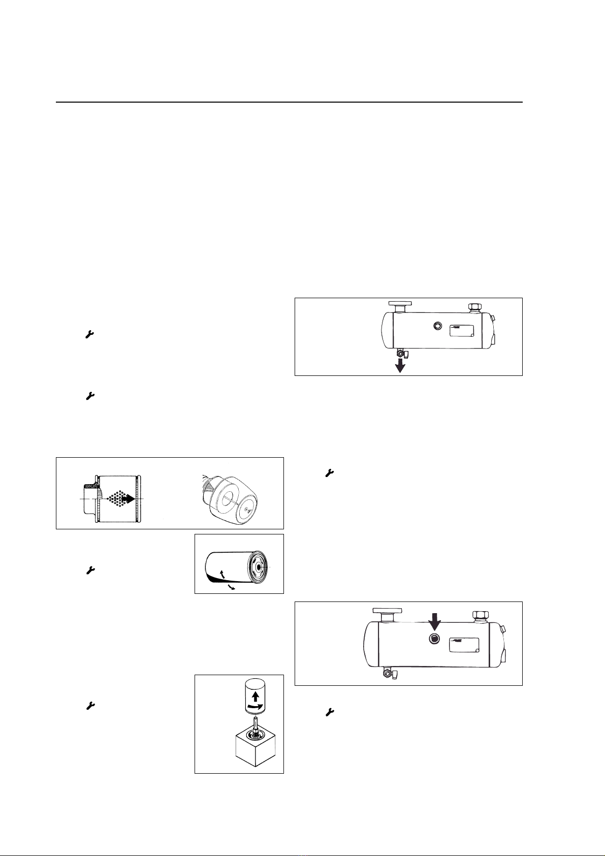
5.2 Oil level check
The maximum oil level is the lower edge of the oil filler neck (11.1).
During operation the oil level will slightly fall by internal distribution.
With rising machine temperature or even a temperature cut-off due
to low oil level, the compressor is to be filled up with fresh oil into the
oil filler neck (11.1).
5.3 Oil quality
With regard to the high load of the lube oil in oil injection cooled
screw-type compressors, we recommend to use very non-aging, water-
repellent, non-foaming, anti-corrosion oils, e.g. our SPECIAL OIL.This
oil is filled in by the works (refer to the oil tank (11) sticker).
FDifferent kinds of oils must not be mixed. In case other lubricants
are used, you should contact the after-sales service p.We only grant
our warranty for the compressors when the use of equivalent lubricants
is verified.
5.4 Initial lubrication of the compressor stage
(04) (refer to section 1.3)
FAfter a longer standstill period, e.g. between initial
commissioning and delivery ex works or after a longer works holiday,
it may happen that there is no oil in the rotor compartment of the
compressor stage (04). This oil, however, is absolutely necessary for
lubricating rotors and bearings in the starting phase. Therefore it is
necessary to fill about 0.2 l. oil into the prelube plug of the suction
valve (06). Manually rotate the compressor stage (04) in the right
direction of rotation until the sensible resistance disappears and the
oil is passed through the stage (04). Mount the prelube plug again
into the suction valve (06).
If no additional oil is available (only use the same kind of oil) the oil
can be drained from the system by means of the oil drain (11.2).
Irregular operating machines and those which are standing still for
several weeks should run for one hour every week, in idle mode, to
prevent corrosion damage.
5.5 Direction of rotating (refer to section 1.3)
FThe direction of rotation must comply with the arrow on the
electric motor (01).When checking, the machine must only be switched
on (and immediately off) for a very short time (max. 0.5 sec.) in order
not to damage the compressor stage (04). The direction of rotation
can be changed when two external conductors are exchanged.
5.6 Starting
Before starting the machine, verify that no persons can be endangered.
The sound cover hood is part of the protection against accidental
contact and leads the cooling air of the machine. It must be closed
during operation. Open the shut-off valve between compressor and
compressed-air system. Switch on the power supply.
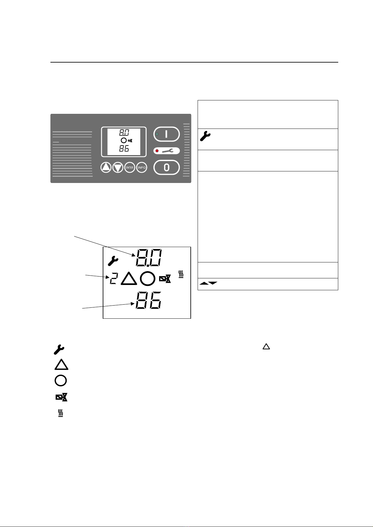
Push the start key I.The green lamp lights up and indicates operation
or, if the line pressure is above the set cut-in pressure, the start
temperature is below + 5°C or with activated remote control, only
flashes stand-by.
CAUTION! A FLASHING GREEN LAMP MEANS THE
COMPRESSOR CAN ALWAYS START UP AUTOMATICALLY
The lines carrying oil and compressed air are to be checked for leakages.
After the cut-out pressure is achieved the machine shuts down after
the set follow-up time (automatic) or changes over to idle running
(load-idle mode).
5.7 Shutdown
Push the stop key O. The green lamp extinguishes. The compressor
shuts down after the follow-up time, the suction valve (06) closes
and the oil tank (11) is relieved. The line pressure is available up to
the non-return valve integrated in the separator box, i.e. the
compressed-air recooler (09) is admitted with line pressure. Program
changing and setting of pressure or time values can only be carried
out with the required code and the compressor at standstill.
6. Compressor maintenance
6.1 General information
FAll maintenance work is to be carried out by trained specialists
with the machine switched off, at standstill, pressure-relieved and
protected against reconnection.
6.2 Pressure relief
Before any maintenance work is carried out, the pressure relief is to
be checked as follows : disconnect the compressor from the
compressed-air system by closing the shut-off valve.The pressure relief
is to be checked by venting the safety valve (12).
FThe temperature of the oil tank (11) may not be more than
+40 °C!
FAttention - caution!
It is absolutely necessary to wear face and body protection
because hot oil mist can penetrate.

10
Suction filter SCK 21-42
Oil filter
Maintenance
6.3 V-belt drive
Our constructions keeps the V-belts (03) at the required tension;
nevertheless they must be checked every 500 hours and retensioned if
necessary.
Place the test pin (pOrder No. 180.02030) at right-angles to aV-belt
(03) in the middle of the section between the rollers and press it down.
Deflection at 50 N testing force: SCK 21 - 31 = 11 - 9 mm
SCK 42, 52 = 8 mm
If you have to replace one V-belt, you must replace all the V-belts (03)
at the same time. To do this release the motor rocker arm upwards
using the adjustment screws. Place the new V-belts (03) individually
around the V-belt pulleys (02) and lower the motor rocker arm using
the adjustment screws until the test force is achieved. Then lock the
adjustment screws again.
6.4.1 Replacement of the suction filter (05) SCK 21-42
Warning 11 - with flashing red lamp. Replace the suction filter (05),
confirm the maintenance with Code 21 and reset with the Okey.
The used suction filter is to be disposed of as special waste.
6.4.2 Replacement of the suction filter (05) SCK 52
Warning 11 - with flashing red lamp. Loosen the filter cap with the
butterfly nut. Replace the suction filter (05) and secure the filter cap
with the butterfly nut again. Confirm the maintenance with Code 21
and reset with the Okey.
The used suction filter is to be disposed of as special waste.
manually tighten it half a turn. Check for leakage at operating
temperature, confirm the main-tenance with Code 21 and reset with
the Okey.
The used oil separator is to be disposed of as special waste.
6.7 Condensate water
When the full capacity of the compressor is not utilized, condensate
water may deposit at the lowest point (heavier than oil) of the oil
tank (11).
This condensate water should be drained through the oil drain (11.2)
regularly, when the compressor is at standstill for a longer period,
e.g. at the weekend (ref. sect. 3.4).
If any condensate water is observed, please contact immediately the
after-sales service p, otherwise your warranty might be endangered.
6.5 Replacement of the oil
filter (15)
Warning 12 - with flashing red lamp.
Loosen the oil filter (15) with a strap
wrench (porder n° 180.06075) and
remove it. Remove residues of the old
sealing from the housing. Lubricate the seal of the new oil filter. Screw
in the new oil filter (15) up to the limit stop and manually tighten it
half a turn. Check for leakage at operating temperature, confirm the
maintenance with Code 21 and reset with the Okey.
The used oil filter is to be disposed of as special waste.
6.6 Replacement of the oil
separator (08)
Warning 13 - with flashing red lamp.
Loosen the oil separator (08) with a strap
wrench (porder n° 180.06075) and
remove it. Remove the residues of the
old sealing and lubricate the seal of the
new oil separator. Screw in the new oil
separator (08) up to the limit stop and
Oil
separator
6.8 Oil level check (mind residual pressure when
opening)
Check the oil level at the oil filler neck (11.1) and refill oil, if necessary.
Different kinds of oil must not be mixed.Works oil filling: SPECIAL OIL.
6.9 Oil change
always together wiht the oil filter (15)
Warning 15 - with flashing red lamp. The oil is to be changed in
accordance with the maintenance intervals on page 13 with the
required oil quantity. In case other lubricants shall be used, please
contact the after-sales service p. We only grant our warranty for the
compressors when the use of equivalent lubricants is verified.
Oil change: (only in warm condition) open the filler neck (11.1) as
well as the oil drain (11.2) and drain the used oil. Close the oil drain
(11.2) and fill in fresh oil up to the lower edge of the filler neck (11.1).
Check for leakage at operating temperature.Confirm the maintenance
with Code 21 and reset with the Okey.
The used oil is to be disposed of as special waste.
Oil filler
05 05
15
Suction filter SCK 52
08
11.2
Condensate and
oil drain
11.1
11.2
6.10 Motor bearings (01)
Warning 14 - with flashing red lamp. Regreasing of the electric
motor (01) must strictly be carried out and is performed by means of
a grease gun with a lubrication nipple according to DIN 3404 (order
n° 180.06076 p). If the electric motor (01) does not have any grease
nipples, it is equipped with long-life grease closed roller bearings.
After their lifetime these bearings are to be changed completely.

11
After 3seconds continuous pushing the O-key,CODE 11 can be called
with the keys followed by ENTER. Call the lower pressure
switch point with the INFO key. Set the required value with the
keys and save it with ENTER. After pushing the INFO key again, the
upper pressure switch point can be called and set with the keys
and saved the same way with ENTER.
6.13 General compressor maintenance
Warning 15 - with flashing red lamp - to carry out a general
compressor maintenance. This general compressor maintenance
includes all maintenance work which is to be done, with the unit in
normal condition and normal ambient. Our after-sales service pwould
be pleased to assist you.
Maintenance
Safety valve
6.11 Safety valve (12)
In order to maintain the proper
function of the safety valve (12),
it is necessary to check the valve
(12) every 2,000 operating hours
or at least once a year.
Checking: dismount the safety
valve (12) from the unit and check
it in a suitable device.
If no device is available, the safety
valve (12) can be checked by us
p.
Remove the residues from the
thread connection. Wrap the
thread of the safety valve (12) with
sealing tape and screw the safety valve in. Check for leakage at
operating temperature.
6.12 Set pressure switch points with Code 11
Maintenance work before after after every each ... operating hours
and compressor erection erection the 1st week #) #) #)
checks week 500 2000 4000
Direktion of rotation (01)
Oil level check (11)
Leak check, discharge temperatur
Reteighten electric connections
Condensate collection (11)
cooler contamination (09,14)
First oil (11) + oil filter (15) change,
V-belts check (03)
Suction filter (05), Öl (11) + oil filter (15)
change, oil separator (08), safety valve (12)
at least once a year
Regreasing of motor bearings (01)
- maintenance intervals depending on
compressor type (refer section 6.10)
General compressor maintenance,
at least once a year
Maintenance intervals #) Warning 100 h before run out service time

12
Troubleshooting
A reminding information due to a run out service time or a run out service interval must be confirmed with Code 21 and reset with the
O- key, after proper service.
A warning has occured when the red lamp flashes with the machine still operating.The warning cause is shown in the display screen. After
proper service, reset the warning with the O- key.
A trouble has occured when the red lamp lights up continuously and the machine is at standstill. The trouble cause is shown in the display
screen. After proper maintenance, reset the trouble with the O- key and the machine can be started up again.
Trouble
7.1 Machine switches off through
compressor dis-charge
temperature; display screen
information
!
15 (red lamp
lights up)
7.2 Falling line pressure
7.3 Machine blows off through
the safety valve (12).
7.4
!
10, or
!
16
(red lamp lights up)
7.5 No automatic start or
switching to load after
previous shutdown when the
set cut-out pressure is
reached or from idling
7.6 Machine does not start when
the start key Iis pushed
7.7 High oil content in the
compressed air (excess oil
consumption).
7.8 Compressor switches off
before the set cut-out
pressure is reached
(red lamp lights up).
7.9 Information
!
3 (red lamp
lights up)
Cause
- Sound absorbing bonnet not closed
- Suction/ambient temperature too high
- Cooling air inlet or outlet blocked
- Oil filter (15) dirty
- Lack of oil
- Oil cooler (14) outside contamination
Attention : all cooler nozzles are to be
counterbacked with a sufficient key;
mind not to overturn the cooler
connections.
- Oil temperature controller (13) defective
- Air consumption exceeds air supply
quantity
- Suction filter (05) dirty
- Relief valve (07) blows off when loading
- Suction valve (06) does not open
- Leakages in the line system
- Upper pressure switch point too high
- Safety valve (12) defective
- means oil separator (08) dirty
- means external high pressure source
- Upper pressure switch point too high
- Interruption in the control circuit
- Ambient temperature below +1°C; the
symbol for temperature flashes
- Line pressure above upper switch point
- Remote control function active
- No power at the compressor
- Electric defect in the control
- Oil return line clogged
- Oil separator (08) defective
- Excess temperature or pressure
- Interruption in the control circuit
- Power voltage below appr. 180 Vac
Measures to be taken
- Close the sound absorbing bonnet
- Vent the compressor compartment
- Clear the cooling air inlet/outlet
- Change the oil filter (15)
- Refill with fresh compressor oil
- Clean with compressed air. At severe
contamination, remove the cooler (09, 14)
unit and clean it with a water jet device
Caution - danger of short circuit!
FNo water jets on electric components!
- Replace the controller (13) insert
- Compressor with higher discharge quantity
required p
- Change the suction filter (05).
- Check the relief valve (07) and replace the
seals, if necessary
- Check the solenoid valve and the suction
valve piston (06) and replace, if necessary
- Check and seal the line system
- Adjust the upper pressure switch point
- Replace the safety valve (12)
- Change the oil separator (08)
- Lower the high pressure source or
eliminate it from the line
- Adjust the upper pressure switch point
- Check the control circuit for interruption
(only by a skilled electrician)
- Install a standstill heating device or heat
the compressor compartment properly
- Observe the line pressure at the display.
- Check flashing display "remote" symbol.
- Check whether power is applied.
- Check the control (only by a skilled el.)
- Clean the oil return line.
- Change the oil separator (08)
- Eliminate the defect in compliance with
chapter point :
- Check the control circuit for interruption
(only by a skilled electrician)
- Check the power supply (only by a skilled
electrician)
refer to
section
1.1, 5.6
1.2, 3.1
3.1
6.5
6.8, 6.9
2
2
page 2
6.4
2
2
3.2
6.12
6.11
6.6
3.2
6.12
Circuit
diagram
3.1
4.1
4.2
Circuit
diagram
2
6.6
7.1, 7.4
Circuit
diagram
Circuit
diagram

13
Options
Tropical version (T) *
The tropical version is suitable for installation in ambient temperatures
of up to 45 °C. Please refer to the separate attached sheet
Special voltage / Frequency 60 Hz *
If your compressor is operated with a non-standard 400 V or with a
frequency of 60 Hz, please refer to the separate, attached description.
Direction of rotation control *
The direction of rotation control prevents damage resulting from the
incorrect polarity of the electrical voltage (phase confusion). The
direction of rotation control causes the automatic shut-down of the
compressor.
The controller shuts down the motor if the pressure switch mounted
on the compressor stage trips. Please see the attached circuit dia-
gram for further details.
Additional heating system *
The additional electric heating system is housed in the compressor’s
oil tank. The oil heating system cuts in automatically as soon as the
temperature falls below the factory set nominal temperature in the
oil tank, which is measured by a temperature sensor.
This prevents the condensation of the air’s humidity in the compressed
air. The additional heating system is required on systems that cut in
and out frequently and temporarily and therefore do not reach the
required operating temperature.
Floating error signal *
An error on the compressor can be forwarded by means of a floating
contact. For example the error message can be connected to a central
controller or a contactor. Please see the attached circuit diagram for
details of the connection terminals.
Floating operating signal *
An operating signal showing whether the main compressor motor is
running, can be connected to the central controller,for example, using
a floating contact or can also be used, for example,to control blowers
of refrigeration driers. Please refer to the attached circuit diagram for
connection details.
Remote On/Off *
The compressed can be switched on and off using a floating contact.
Please refer to the attached circuit diagram for further details.
Proportional controller *
The proportional controller makes it possible to adjust the delivery
rate to the actual consumption of compressed air.To achieve this the
air delivery rate is throttle in the intake controller by narrowing the
cross-section.
Soiling indicator, intake filter *
If the intake filter becomes soiled this is shown on the display. The
filter element must then be replaced.The filter soiling is measured by
a differential pressure sensor over the intake filter.
Soiling indicator, oil filter *
If the oil filter becomes soiled this is shown on the display. The oil
filter cartridge must then be replaced.The filter soiling is measured by
a differential pressure sensor over the oil filter.
Soiling indicator, oil separator cartridge *
If the oil separator becomes soiled, this is shown by the controller on
the display. The oil separator cartridge must then be replaced. The
fine separator soiling is measured by a differential pressure sensor
over the oil filter.
Heat recovery system *
If you system is fitted with a heat recovery system or is prepared for a
heat recovery system, please refer to the separate attached description.
* The above options are not included in the standard version. These
instructions must only be observed if your compressor is fitted with
the appropriate option.

14
Technical Data
Performance and erection data:
General data:
Electrical data:
Com- Weight Cooling Supply Flue air Oil tank Number of Type of Compressed
pressor air air duct cross capacity V belts V belts air
volume opening section connection
kg m3/h m2m2lG
Com- Motor Currents at 220V/60Hz Currents at 400V/50Hz Currents at 550V/50Hz Maximum
pressor rating switching
frequency
kw 1/h
Site Site Site
back-up back-up back-up
I(rated) I(max) fuse I(rated) I(max) fuse I(rated) I(max) fuse
A A A gL A A A gL A A A gL
973
1270
waste air
dashboard
power
supply
PG 36
M10 int. M10 int.
compr. air
outlet
fresh air
compr. air
outlet
412
65
677
795
1070
exhaust shaft
connection
669
219
4 x M5 int.
cooling air opening
without shutter or mash
min. wall distance 50 cm
dashboard
service side
SCK 21 15,0 48 52 63 30 32 50 22 24 35 30
SCK 26 18,5 58 64 80 34 38 50 25 27 35 25
SCK 31 22,0 70 77 80 40 45 63 29 32 50 20
SCK 42 30,0 90 99 125 57 63 80 42 46 50 15
SCK 52 37,0 119 131 160 67 73 100 48 53 80 12
SCK 21 435 3300 0,40 0,37 8,0 3 XPA 1
SCK 26 450 3300 0,40 0,37 8,0 3 XPA 1
SCK 31 485 3500 0,40 0,39 8,0 3 XPA 1
SCK 42 580 5300 0,60 0,60 17,0 3 XPA 1 1/2
SCK 52 595 5700 0,65 0,65 17,0 4 XPA 1 1/2

15
Spare parts: Plan and electric parts
The serial number of the screw
compressor (on the name plate) is to
be indicated in any spare parts order.
The required part number can be
defined by the following views.
136. 185 136. 64
176. 163
K1
132. 6 2
132. 6 3
132. 6 7
K3
132. 6
132. 6 2
132. 6 3
K2
132. 5 1
136. 272
136. 278
137. 8744
137. 9
132. 6 2
132. 6 3
132. 6 7
136. 12

16
Spare parts: Unit parts
213. 489 273. 1852
273. 1853
172. 255
172. 7787
273. 4
273. 41
213. 49
226. 376
226. 377
12 . 11
172. 222
136. 1 3
137. 462
174. 7
228. 851
228. 852
154. 15
154. 154
172.111 2
172.58111
273. 1578
273. 1579
278. 222
278. 23
278. 246
278. 519
213. 456
278. 224
176. 369
176. 381
176. 384

17
Spare parts: Unit parts
276. 44
213. 457
127. 66
127. 177
278. 366
278. 377
126. 318
126. 3224
126. 328
126. 428
213. 489
172. 78
176. 95
131. 3 1
131. 3 2
131. 3 3
131. 3 4
131. 3 5
26 . 47
174. 13
278. 237
173. 3
278. 277
278. 338
278. 339
163. 9
163. 26
163. 29
163. 44
163. 51
163. 66
163. 68
163. 129
136. 128
136. 131
163. 168
226. 3112
226. 3118
226. 3125
226. 3132
226. 314
226. 315
226. 318
226. 4 95
226. 41 6
226. 4126

18
Spare parts: Lines and gaskets
173. 199
165. 1332
165. 4418
167. 77
173. 11
173. 286
173. 39
165. 168
165. 246
167. 77
167. 1249
165.832 2
165. 17
173. 29
173. 292
173. 1 7
165.832 2
167. 8 26
167. 544

19
Spare parts: Lines and gaskets
173. 286 165. 331 165. 33
173. 8176
173. 291
165. 12
167. 77
165.832 2
165. 3416
229. 38
229. 39
167. 77
165.832 2
173. 288
173. 289
165.832 2

20
Spare parts: Suction control and temperature control
173. 4 1
173. 4 3
165.151 1
172. 222
273. 2 55
212. 211
212. 21
212. 211
212. 213
This manual suits for next models
4
Table of contents
Popular Air Compressor manuals by other brands

airmaster
airmaster TIGER 11/510 Operation & maintenance instructions

sunjoe
sunjoe 24V-AJC-LTE-RM Operator's manual

nuair
nuair Super Boxy Instructions for use manual

pilotair
pilotair ALTA-TEC Series User’s Maintenance & Spare Parts Manual

pilotair
pilotair K17D Instructions and parts list

BOSSCO
BOSSCO 210 DUS JD4045 Service and maintenance manual

Sullair
Sullair 1800 user manual

Danfoss
Danfoss Turbocor Twin-Turbine TTS Series Applications and Installation Manual

NARDI COMPRESSORI
NARDI COMPRESSORI PACIFIC D23 User and maintenance manual

Craftsman
Craftsman 921.16472 owner's manual

Vmac
Vmac VR70 installation manual

Ingersoll-Rand
Ingersoll-Rand HP915WCU Operation & maintenance manual