Aluprof DC 318 User manual

1
We reserve the right to any technical change.
Valid on 2022.04.04
OPERATING MANUAL FOR UNDER PLASTER SWITCH WITH RADIO RECEIVER DC 318
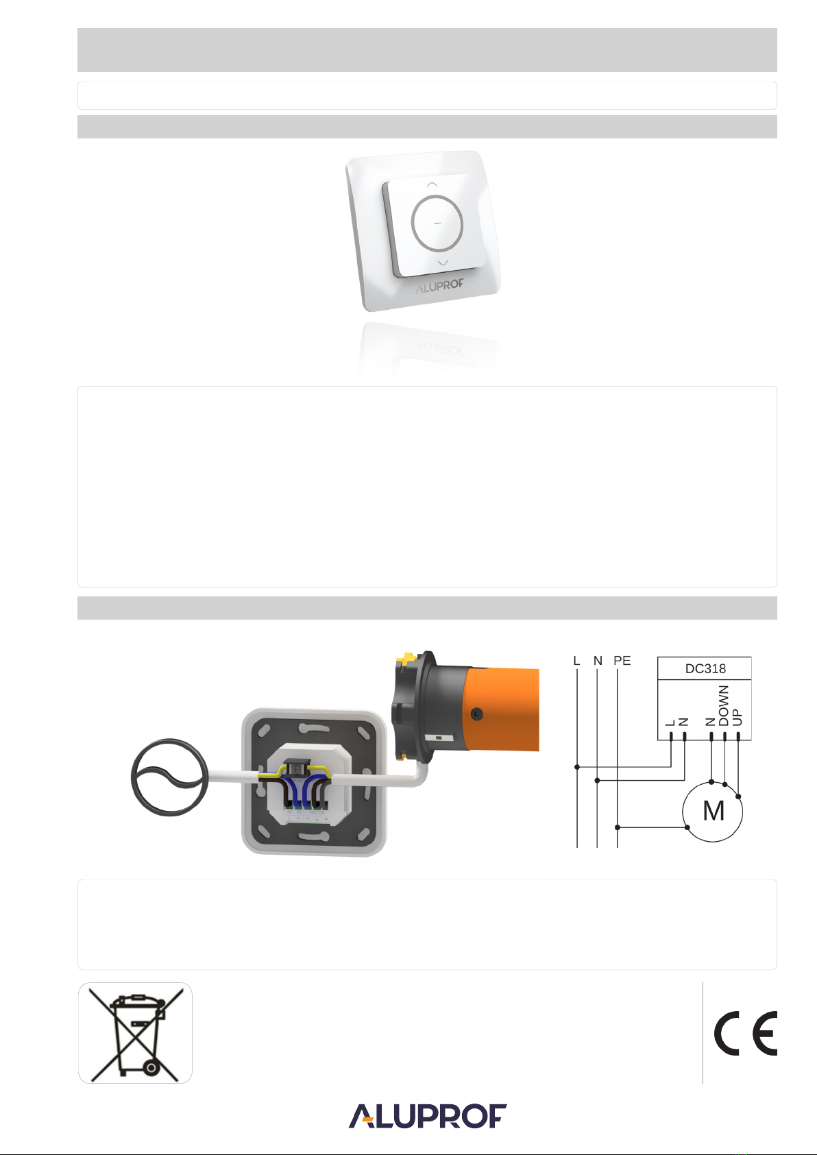
2. ILLUSTRATIVE SWITCH CONNECTION
Power supply:
Operating temperature:
Works exclusively with motors without built-in radio control.
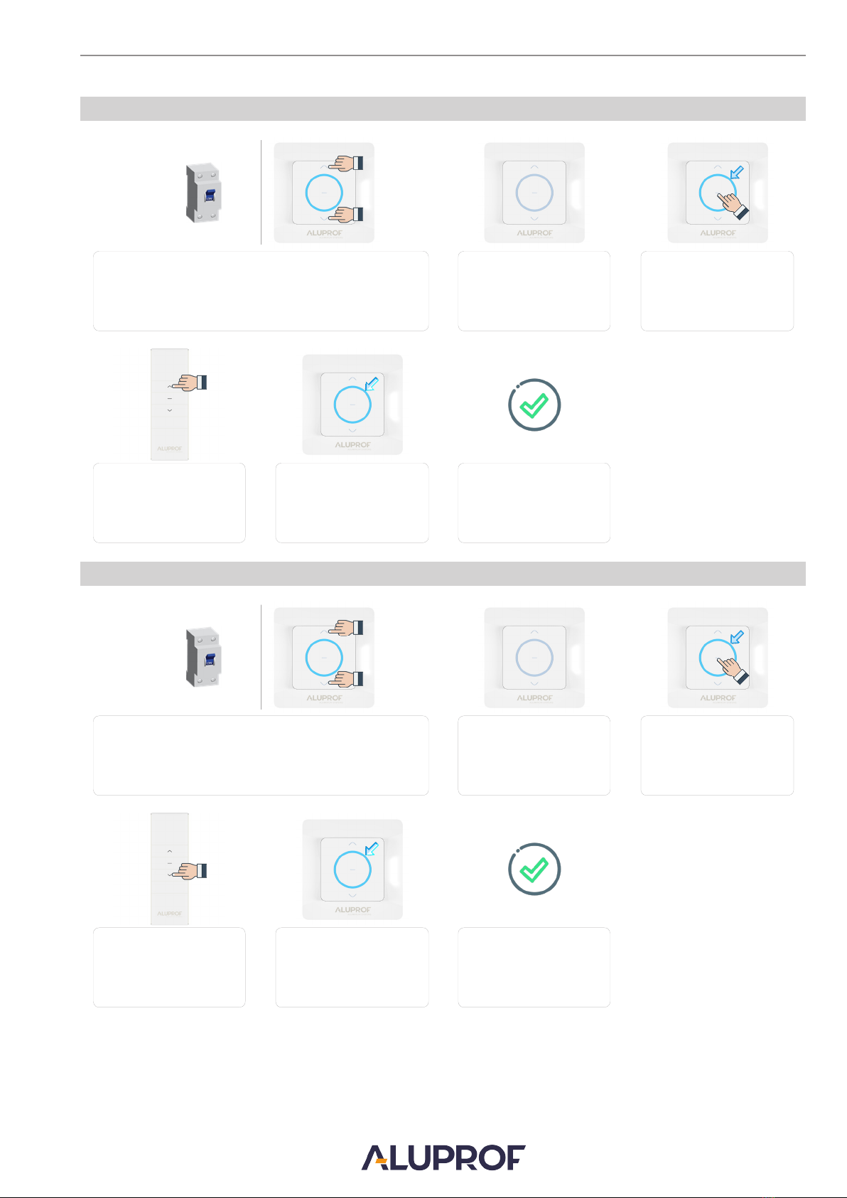
Works with all DC series transmitters included in the ALUPROF S.A. offer.
Possibility to program up to 20 transmitters, Each next transmitter will erase the first one.
230 VAC / 50 Hz
~ -10°C - ~ +55°C
Average range: 200 meters (in open space), 35 meters (inside buildings)
Frequency: 433.92 MHz
Company reserves the tolerance of catalog data due the different conditions usage.
In accordance with the provisions of the Directive of the European Parliament and of the Council 2012/19 / EU of 4 July 2012
on waste electrical and electronic equipment (WEEE), it is prohibited to place of used equipment together with other wastes,
marked with crossed out wheeled bin symbol. The users are obliged to transfer their used equipment to a designated collection
point for proper processing. The marking means, at the same time, that the equipment was put on the market after 13 August
2005. These legal obligations have been introduced to reduce the amount of waste generated from waste electrical and
electronic equipment and to ensure an appropriate level of collection, recovery and recycling. The equipment does not contain
any dangerous components, which would have any particularly negative impact on the environment and human health.
Applied for max 50 Nm tubular motor
230V / 50Hz
- Installation of the switch should be carried out by authorized persons (e.g. ECS authorisations to operate electrical devices up to 1 kV).
- The switch is designed for use in dry rooms and should not be exposed to direct weather conditions.
- The switch should be powered by a separate circuit and protected by a quick fuse for example: circuit breaker type B10.
NOTE
OPERATING MANUAL FOR UNDER PLASTER SWITCH WITH RADIO RECEIVER DC 318
1. TECHNICAL SPECIFICATIONS
Failure to comply with this Manual may result in injury or death.
Keep the Manual for reference.
80 x 80 (mm)Dimensions:
Radiated power: 10 miliwat (mW)

2
We reserve the right to any technical change.
Valid on 2022.04.04
OPERATING MANUAL FOR UNDER PLASTER SWITCH WITH RADIO RECEIVER DC 318
3. REMOTE CONTROLLERS
LEGEND
UP - activation of this button will move curtain up.
DOWN - activation of this button will move curtain down.
P2 - activation of this button will switch to programming mode.
K+ - activation of this button will switch to the next channel.
K- - activation of this button will switch to the previous channel.
K2 - second channel buttons.
K1 - first channel buttons.
MODE - button activates the settings of the clock and date.
Activation of the “P2”button in remote controller DC1670, DC1671, DC315, DC2291 is performed by a combination of both
keys “STOP” and “UP”.
DC 305 DC 306 DC 313 DC 920
P2 P2
K-
UP
STOP
K+
DOWN
UP
STOP
DOWN
MODE P2 OK MODE P2 OK
UP
STOP
DOWN
P2
UP
STOP
DOWN
UP
STOP
DOWN
UP
STOP
DOWN
K1 K2
UP
STOP
DOWN
MODE
K-
K+ K+
P2
K-
UP
STOP
DOWN
UP
STOP
K+
K-
DOWN
P2
Activation of the “P2” button in DC1675, DC1676 wall transmitters is
performed by a combination of both keys “MODE” and “K+”.
UP
STOP
KEY LOCK
DOWN
DC 287
DC 289 DC 288
DC 448 DC 661 DC 229
DC 315
DC 1670 DC 1671
DC 1675 DC 1676 DC 1673
DC 1600 DC 1602
DC 2291

3
We reserve the right to any technical change.
Valid on 2022.04.04
OPERATING MANUAL FOR UNDER PLASTER SWITCH WITH RADIO RECEIVER DC 318
4. MEMORIZING THE TRANSMITTER
After 3 seconds when the indicator
light turns off - release the buttons.
Press “STOP” button. The
indicator light turns on.
Press the„UP” button on the
transmitter.
Indicator light flashes
3 times.
The transmitter has been added.
Press and hold simultaneously“UP” and “DOWN”buttons with
power supply on.The indicator light is on.
5. ERASING ONE TRANSMITTER.
Press and hold simultaneously“UP” and “DOWN”buttons with
power supply on.The indicator light is on.
After 3 seconds when the
indicator light turns off - release the
Press “STOP” button.
The indicator light turns on.
Press the„DOWN” button on the
transmitter.
Indicator light flashes
3 times.
The transmitter has been
deleted.
buttons.

4
We reserve the right to any technical change.
Valid on 2022.04.04
OPERATING MANUAL FOR UNDER PLASTER SWITCH WITH RADIO RECEIVER DC 318
Press and hold simultaneously ”UP”and “STOP”buttons with power
supply on.The indicator light is on.
After 6 seconds
indicator light flashes 3 times.
The setting has been saved.
Pulse mode enables, i.a. step control of venetian blind.
6. CHANGING THE OPERATING MODE (PULSED / CONTINUOUS)
7. RESTORE FACTORY SETTINGS
Press and hold simultaneously“STOP” and “DOWN” buttons with
power supply on.The indicator light is on.
After 6 seconds
indicator light flashes 3 times.
Factory settings restored
Headquarters; Production plant in Bielsko-Biała:Production Plant in Opole;
Warszawska 153, 43-300 Bielsko-Biała, Poland,ul. Gosławicka 3, 45-446 Opole, Poland,
tel. +48 33 81 95 300, fax +48 33 82 20 512tel. +48 77 40 00 000, fax +48 77 40 00 006
e–mail: [email protected]
Other Aluprof Receiver manuals