
Assembly instructions BR 133-3 to 139-3 Status 03/2022 Former instructions lose their validity. 7 / 14
• Align an iso-floor with steel longitudinal supports so that the
screw thread inserts in the floor are located over the elongated holes
of the longitudinal supports (distance according to type sheet). The
separation distance to the driver cab is absolutely to be adhered to.
Tip: Use a mandrel (Fig. 3213) in order to bring the bores of the
longitudinal supports in line with those of the floor.
• Insert the screws MD100354 into the bores and screw them down
with several turns of the thread. If they can be screwed down with-
out impairment of the freedom of motion, tighten them crosswise
with the required torque (Fig. 3214).
• Align the rear longitudinal support close-off to the hole pattern in
the floor. Use a mandrel to check whether the hole pattern in the
longitudinal support is in line with the bore in the floor (Fig. 3215).
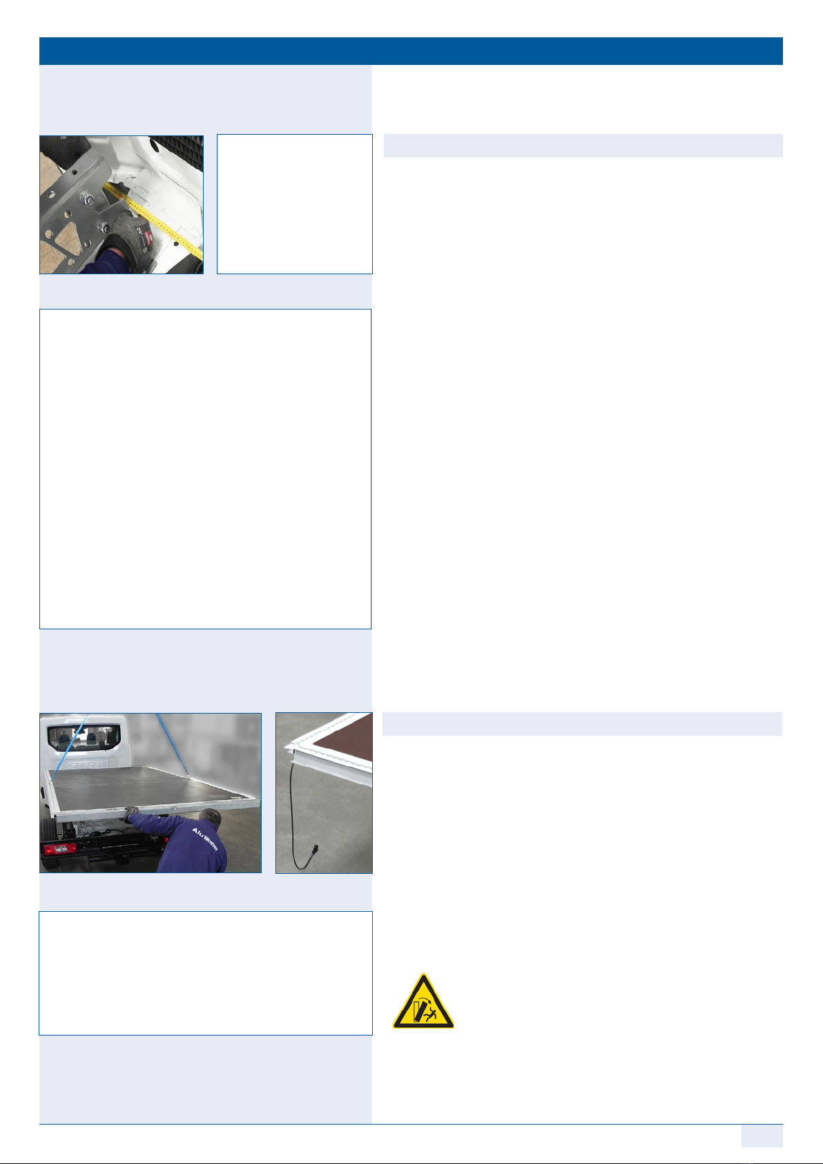
3.3 Assembling of the side walls
• Lift with a suitable lifting aid (crane with appropriate hoisting
gear, vacuum cross beam or lifting plate) the 1st side wall in the
centre of gravity (Fig. 331). Observe the safety instructions!
Tip: It is best to fix the rear walls with glue pliers in order to prevent
damage to the side wall.
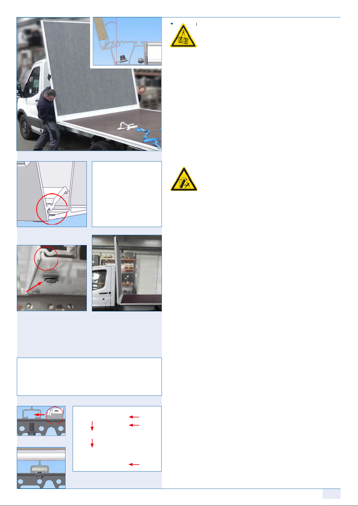
• Ensure that no cables are present between connection points (dan-
ger of crushing of the cables). They must hang down freely on the
beginning and end of the wall (Fig. 330 a/b).
• As with the front-side wall assembly, set the lower chord of the wall
diagonally (approx. 10-15°C) into the floor profile (Fig. 331/324).
• Rotate the module assembly screws MD 100318 into the appropriate
bores in order to fix the latching point (with MD 110044), and tighten
them by several turns of the thread (Fig. 332). With the bedding of the
side wall, the corner pillar touches the frame cross beam (Fig. 333).
Further assembly is not hindered by this.
Attention: Before the raising of the side wall, the front wall
should stand vertically and the corner pillar overlap
the front-side wall panel.
• Raise the side wall up to the second latching point until it engages
with a noise ("click") (Fig. 334/336).
• Visually check whether the nose has engaged in the profile and
whether a clearance still exists, in particular in the side door area.
Where appropriate, press down in order to ensure engagement. Once
again, check for a flush line and gap dimensions (Fig. 334/327).
• The frame pillar should now fit flush with the frame cross beam and
both are at right angle to each other below (Fig. 335). Now tight-
en the screws used at the beginning securely with the appropriate
torque.
• In the interior of the box, fix all walls with the module assembly
screws for the interior area MD 100224 (Fig. 337).
Attention: Unlike those for the outer area (MD100318), these screws
have no gasket and are provided with a cylindrical
head.
• Proceed with the assembly of the 2nd side wall just like with
the 1st side wall (Fig. 338 /339).
Proceed with the assembly of the 2nd side wall just like with
Lift with a suitable lifting aid (crane with appropriate hoisting
gear, vacuum cross beam or lifting plate) the 1st side wall in the
Fig. 3213 Fig. 3214
Fig. 3215
Fig. 330a Fig. 330b
Fig. 332
Fig. 331 Fig. 333
Fig. 339
Fig. 334
Fig. 336 Fig. 337
Fig. 338
Fig. 335


 Operator's manual")


