Amada IT-H1062A3W User manual

Z05OM1203632-07
OPERATION MANUAL
INVERTER-TYPE WELDING TRANSFORMER
IT-H1062A3W

IT-H1062A3W
1
Thank you for purchasing our Inverter-Type Welding Transformer IT-H1062A3W.
・This operation manual explains its method of operation and precautions for use.
・Before using, read this operation manual carefully; after reading, save it in a proper place
where you can easily access.
Contents
1. Special Precautions
(1) Safety Precautions .......................................... 1-1
(2) Precautions for Handling ................................. 1-4
(3) On Disposal .................................................... 1-4
(4) Shipping Kit..................................................... 1-5
2. Connection and Circuit Diagram
(1) Connection...................................................... 2-1
(2) Circuit Diagram ............................................... 2-2
3. Outline Drawing and Specifications
(1) Outline Drawing............................................... 3-1
(2) Specifications.................................................. 3-2
(3) SENS Output................................................... 3-2
(4) Duty Cycle Graph............................................ 3-3
4. Comparison with SIT-F241-HC
(1) Specifications.................................................. 4-1
(2) Duty Cycle Graph............................................ 4-1
(3) Options............................................................ 4-1

IT-H1062A3W
1. Special Precautions
1-1
1. Special Precautions
(1) Safety Precautions
Before using, read "Safety Precautions"
carefully to understand the correct method
of use.
■These precautions are shown for safe use
of our products and for prevention of
damage or injury to operators or others.
Be sure to read each of them, since all of
them are important for safety.
■The meaning of the words and symbols is
as follows.
These symbols denote
"prohibition".
They are warnings
about actions out of the
scope of the warranty
of the product.
These symbols denote
actions which
operators must take.
Each symbol with a
triangle denotes that
the content gives
notice of DANGER,
WARNING or
CAUTION to the
operator.
Denotes operations and practices that
may imminently result in serious injury
or loss of life if not correctly followed.
Denotes operations and practices that
may result in serious injury or loss of
life if not correctly followed.
Denotes operations and practices that
may result in personal injury or damage
to the equipment if not correctly followed.
Do not touch the “Terminal block” on the rear panel of the Welding
Transformer
Since very high voltage is applied to the “Terminal block”, it is very dangerous
to touch it unnecessarily. When connecting or disconnecting a cable, be sure to
turn off the power. After connecting the cable, install the terminal cover so that
operator can not touch the terminal block during work.
Never disassemble, repair or modify the Welding Transformer
These actions can cause electric shock and fire. Consult us or your distributor
for inspection and repair.
Never burn, destroy, cut, crush or chemically decompose the Welding
Transformer
This product incorporates parts containing gallium arsenide (GaAs).
DANGER
!
WARNING
!
CAUTION
!
DANGER
!

IT-H1062A3W
1. Special Precautions
1-2
Do not put your hands between the electrodes
When welding, keep your fingers and hands away from the electrodes.
Ground the Welding Transformer
If the Transformer is not grounded, you may get an electric shock when there
is trouble, or when electricity leaks.
Use the rated voltage
Applying a voltage exceeding rated voltage can cause abnormal heat and
fire.
Do not touch +/- terminal, secondary cable, any welded part or electrodes
during welding and just after welding finished
These parts are very hot. Do not touch them; otherwise you may be burnt.
Do not damage the power cable and connecting cables
Do not tread on, twist or tense any cable. The power cable and connecting
cables may be broken, and that can cause electric shock and fire. If any part
needs to be repaired or replaced, consult us or your distributor.
Wear protective glasses
If you look at the flash directly during welding, your eyes may be damaged.
If any spatter gets in your eye, you may lose your eyesight.
Stop the operation if any trouble occurs
Continuous operation after occurrence of a trouble such as burning smell,
abnormal sound, abnormal heat, smoke, etc. can cause electric shock and
fire. If such a trouble occurs, immediately consult us or your distributor.
Persons with pacemakers must stay clear of the welding machine
A person who uses a pacemaker must not approach the welding machine or
walk around the welding shop while the welding machine is in operation,
without being permitted by his/her doctor. The welding machine generates a
magnetic field and has effects on the operation of the pacemaker while it is
turned on.
Protective gear must be worn
Put on protective gear such as protective gloves, long-sleeve jacket, leather
apron, etc. Spatter can burn the skin if they touch the skin.
W
A
RNING
!

IT-H1062A3W
1. Special Precautions
1-3
Do not use this Welding Transformer for purposes other than welding
Use of this equipment in a manner other than specified can cause an electric
shock and fire.
Use proper tools (wire strippers, pressure wire connectors, etc) for
termination of the connecting cables
Do not cut the conductor of wire. A flaw on it can cause fire and electric
shock.
Install the Welding Transformer on firm and level surface
If the Transformer falls or drops, injury may result.
Do not splash water on the Welding Transformer
Water splashed over the electric parts can cause electric shock and short
circuits.
Do not place a water container on the Welding Transformer
If water spills, insulation will deteriorate, and this may cause electric leak and
fire.
Keep combustible matter away from the welding machine
Spatter can ignite combustible matter. If it is impossible to remove all
combustible matter, cover them with non-combustible material.
Do not cover the Welding Transformer with a blanket, cloth, etc.
If such a cover is used, it may be overheated and burn.
Keep a fire extinguisher nearby
Keep a fire extinguisher in the welding shop in case of fire.
Use ear protectors
Loud noises can damage hearing.
Maintain and inspect the Welding Transformer periodically
Maintain and inspect the Transformer periodically, and repair any damage
nearby before starting operation.
CAUTION
!

IT-H1062A3W
1. Special Precautions
1-4
(2) Precautions for Handling
When transporting or moving the Transformer, do not lay it down. Also, handle
the Transformer with care so as not to make an impact such as drop on it.
Moving the Transformer by hand must be done by at least two people.
Install this Welding Transformer on a firm and level surface. If it is inclined,
malfunction may result.
Do not install this Welding Transformer in the following:
•Damp places where humidity is higher than 90%,
•Hot or cold places where temperatures are above 45°C or below 5°C,
•Places near a high noise source,
•Places where chemicals are handled,
•Places where water will be condensed,
•Dusty places,
•Places exposed to large amounts of vibration or shock, and
•Places at an altitude above 1000 meters.
Clean the outside of the Welding Transformer with a soft, dry cloth or one wet
with a little water. If it is very dirty, use diluted neutral detergent or alcohol. Do
not use paint thinner, benzine, etc., since they can discolor or deform the
Welding Transformer.
For the water-cooled products, use city water or water for industrial use. Note
that the water temperature, flow rate and water pressure fall within the specified
range.
Do not put a screw, a coin, etc., in the Welding Transformer, since they can
cause a malfunction.
Operate the Welding Transformer according to the method described in this
Operation Manual.
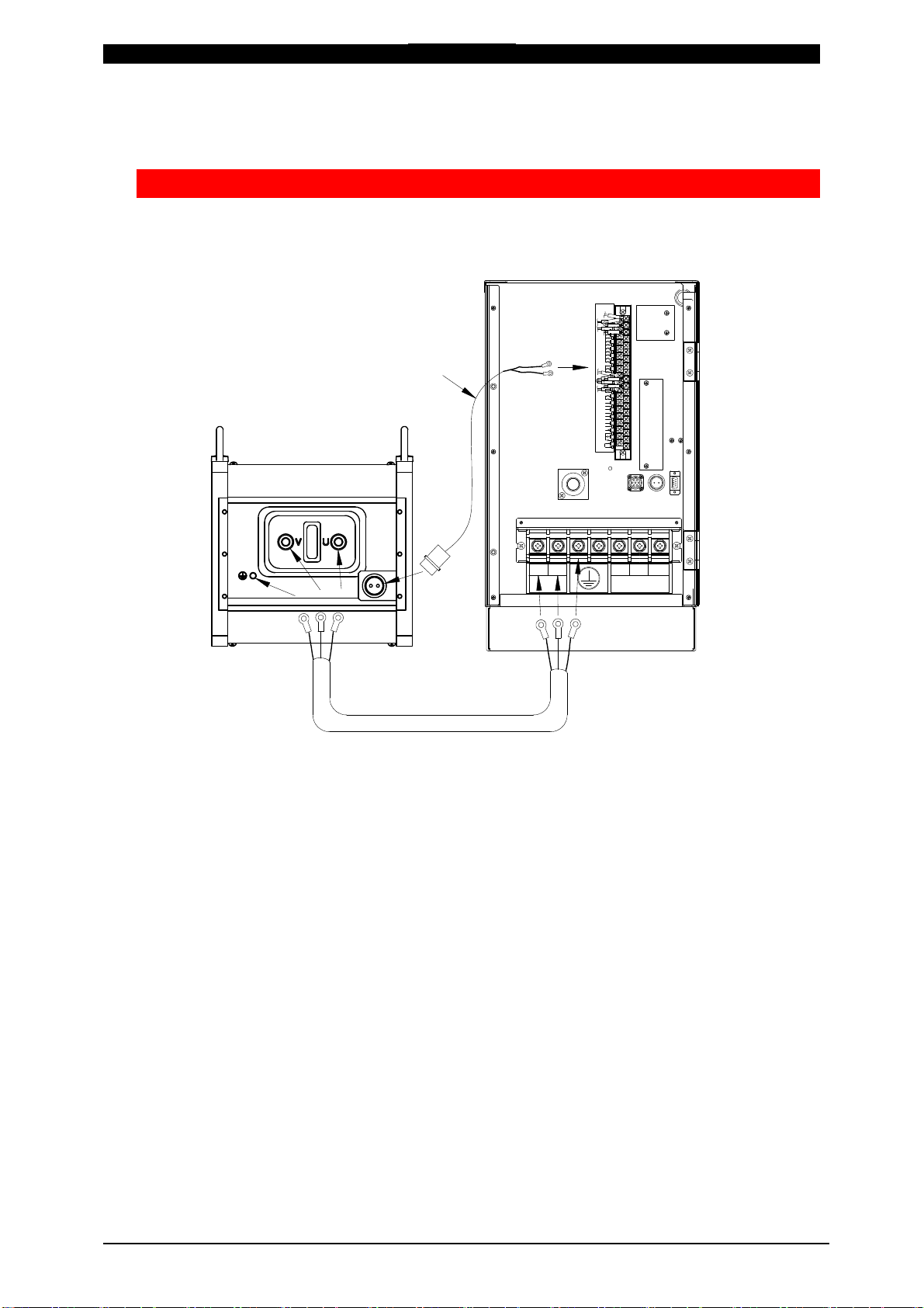
The welding power supply, the welding head, and the cables for connecting the
welding power supply, the welding head and the Transformer are separately
needed to use the Transformer.
When the Transformer has the I/O signals, the I/O signal line to start the
Transformer is not attached.
(3) On Disposal
This product incorporates parts containing gallium arsenide (GaAs). At the time of
disposal, separate it from general industrial waste or domestic waste and carry out
the disposal in accordance with applicable laws and regulations.

IT-H1062A3W
1. Special Precautions
1-5
(4) Shipping Kit
Verify that contents of the container agree with the kit list.
If you see any damage, please contact us.
Packaged Kit Quantity
IT-H1062A3W 1
Operation Manual 1
Options
Item Model No.
(Item No.) Specifications Conformity
Welder Remarks
Thermal
sensing
cable
SK-1205604
(1205604)
Cabtyre cable
0.5 sq-2 cores, 2 m
IS-800A
IS-1400A
Metal connector / Crimping terminal
(2P connector / Terminal for M3.5)
SK-1205605
(1205605)
Cabtyre cable
0.5 sq-2 cores, 3
m
SK-1205606
(1205606)
Cabtyre cable
0.5 sq-2 cores, 5
m
Output
cable
PK-1209847
(1209847)
600 V VCT cable
22 sq-3 cores, 2 m
IS-800A
Power supply side: M8 terminal (3)
Transformer side: M8 terminal (2)
M6 terminal (1)
PK-1209848
(1209848)
600 V VCT cable
22 sq-3 cores, 5 m
PK-1209849
(1209849)
600 V VCT cable
22 sq-3 cores, 10 m
PK-1205244
(1205244)
600 V VCT cable
22 sq-3 cores, 2 m Power supply side: M8 terminal (3)
Transformer side: M8 terminal (2)
M6 terminal (1)
CE compliant
PK-1205245
(1205245)
600 V VCT cable
22 sq-3 cores, 5 m
PK-1205246
(1205246)
600 V VCT cable
22 sq-3 cores, 10 m
PK-1209850
(1209850)
600 V VCT cable
22 sq-3 cores, 2 m
IS-1400A
Power supply side: M12 terminal (2)
M10 terminal (1)
Transformer side: M8 terminal (2)
M6 terminal (1)
PK-1209851
(1209851)
600 V VCT cable
22 sq-3 cores, 5 m
PK-1209852
(1209852)
600 V VCT cable
22 sq-3 cores, 10 m
PK-1208454
(1208454)
600 V VCT cable
22 sq-3 cores, 2 m Power supply side: M12 terminal (2)
M10 terminal (1)
Transformer side: M8 terminal (2)
M6 terminal (1)
CE compliant
PK-1208455
(1208455)
600 V VCT cable
22 sq-3 cores, 5 m
PK-1208456
(1208456)
600 V VCT cable
22 sq-3 cores, 10 m

IT-H1062A3W
2. Connection and Circuit Diagram
2-1
2. Connection and Circuit Diagram
(1) Connection
Example connection with the inverter-type welding power supply
21
19
1
1
5
3
22
OUT5
OUT4
OUT3
OUT2
/COUNT RESET
WE3 STOP
/WELD COUNT
WE2 STOP
/PARITY
WE1 STOP
SCH128
SCH64
SCH32
SCH16
SCH 8
SCH 4
SCH 2
39
38
37
36
35
34
33
32
31
30
29
28
27
26
25
24
16
15
14
13
12
11
10
9
8
7
6
VOLT SENS
SOL 2
SOL 1
SOL COM
SOL POWER
OUT COM
OUT1
NG1(ERROR)
STEP RESET
1ST
COM
NG2(CAUTION)
CONTROL SIG
18
20
18
4
2
23
17
4
ERROR R ESET
2ND
LB1157291
PE
~AC240V
AC200V
INPUT
OUTPUT
L3L2
L1
VU
SENS
Output cable
Inverter-type welding power supply
IT-H1062A3W
VU
PE
Thermal sensing cable
The output cable and thermal sensing cable are sold separately.
The terminal screw of IT-H1062A3W is M8 (PE terminal is M6).

IT-H1062A3W
2. Connection and Circuit Diagram
2-2
Example connection with the welding head and the cooling water
IT-H1062A3W
Inner dia. φ12 tube
Secondary
conductor
Water
outlet
Water
inlet
Welding
head
(2) Circuit Diagram
-
+
SENS
THS
E
U
V
S
P
Diode thermostat

IT-H1062A3W
3. Outline Drawing and Specifications
3-1
3. Outline Drawing and Specifications
(1) Outline Drawing
(Dimensions in mm)
OUT
IN
190
(35)
470 (25)
175 (33)
25
70
305
10 30
55
(50)
4-φ8.5
M10
+ output
terminal
Hose inlet
tube for inner dia. φ12
4-M8, 20 deep
(Common to +/- terminal)
Dimensions of output terminal
325 (for mounting)
SENS
(With the terminal cover removed)
Power supply
terminal, M8
Grounding
terminal, M6
175
- output
terminal
Thermal
output
Cable gland
(φ33)

IT-H1062A3W
3. Outline Drawing and Specifications
3-2
(2) Specifications
Rated supply voltage 300
V AC
Number of phases 1
Rated frequency 1
kHz
Rated permanent
apparent input power 31.2
kVA (100% rating)
No-load voltage values 12.5
V (Turn ratio: 24:1)
Output current under
load condition 8500
A (Resistance load: 800
μΩ)
Permanent output
current 2493
A
Maximum duty cycle 8.6% (8500
A)
Cooling method Water cooling
Rated cooling liquid
flow
30°C or less, 3
L/min. or more (Water pressure: 0.2
MPa or more and 0.5
MPa or less)
SENS output 70°C, B-contact thermal sensor
Operating environment
Temperature +5°–+45°C, Humidity 90% or less
(Dew condensation not allowed), Altitude 1000
meters or lower
Caution: Use this product in the environment
without conductive dust. If conductive dust
enters in the product, this may result in a
failure, electric shock, or fire. When using
this product in this environment, make
contact with us.
Storage environment Temperature -10°–+55°C and dew condensation
not allowed
Insulation class F
Protection class IP20
Protection class for
electric shock I
Compliance standards ISO 5826:2014
Mass 25
kg
Outline dimensions 175
(H) mm × 190
(W) mm× 470
(D) mm (Not
including projections)
(3) SENS Output
Connector, SNS-1602-RM
(SANWADENKIKOGYOCo.,Ltd.)
or
Thermal sensing cable (option)
THS
SENS

IT-H1062A3W
3. Outline Drawing and Specifications
3-3
(4) Duty Cycle Graph
Environment: Temperature 45°C or less
Water temperature 30°C or less
Flow rate 3
L/min. or more
8.6% (8500A)
10%
20%
30%
40%
100%
Output current [A]
Duty cycle [%]

IT-H1062A3W
4. Comparison with SIT-F241-HC
4-1
4. Comparison with SIT-F241-HC
(1) Specifications
SIT-F241-HC IT-H1062A3W
Conformity welder
IS-300A/600A/800A/1400A
Cooling method Water cooling
Outline dimensions
240 (H) × 180 (W) ×
481 (D) mm
175 (H) × 190 (W) ×
470 (D) mm
Mass
35 kg 25 kg
Output current
under load
condition
6800
A
(Resistance load: 800
μΩ)
8500
A
(Resistance load: 800
μΩ)
Maximum output
current
14400 A (Duty cycle: 10%, Resistance load: 299 μΩ)
Turn ratio
24:1
(2) Duty Cycle Graph
(3) Options
SIT-F241-HC
IT-H1062A3W
Name
SENS cable Thermal sensing cable
Model No.
SEN-C20-C2SGO SK-1205604
SEN-C30-C2SGO SK-1205605
SEN-C50-C2SGO SK-1205606
0 20 40 60 80 100
16000
14000
12000
10000
8000
6000
4000
2000
0
Black dotted line: SIT-F241-HC Gray solid line: IT-H1062A3W
Output current [A]
Duty cycle [%]
020 40 60 80 100
Table of contents
Other Amada Transformer manuals
Popular Transformer manuals by other brands

Jobsite
Jobsite BT-V Installation and user guide

Audio Note
Audio Note AN-S5 Owner's information manual

AquaStar
AquaStar LST100 Installation, operation and service manual

Beckhoff
Beckhoff SCT Series Documentation

Waukesha
Waukesha INERT AIR N2 manual

SECO-LARM
SECO-LARM Open-Frame Transformers ST-UV16-W100Q Specification sheet