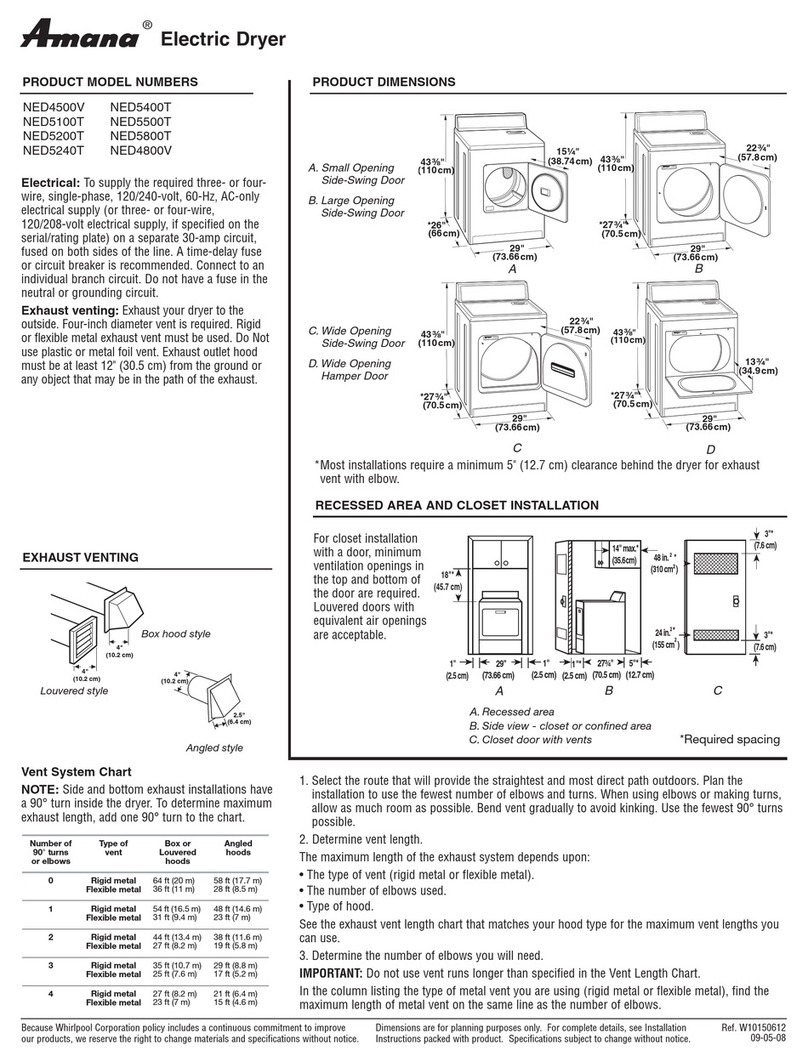
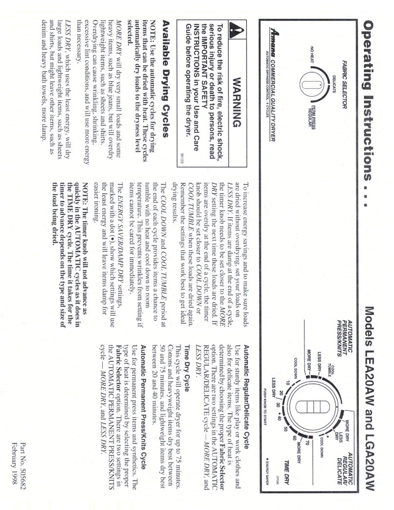
Amana SDE515DAYW Manual
Other Amana Dryer manuals
Amana
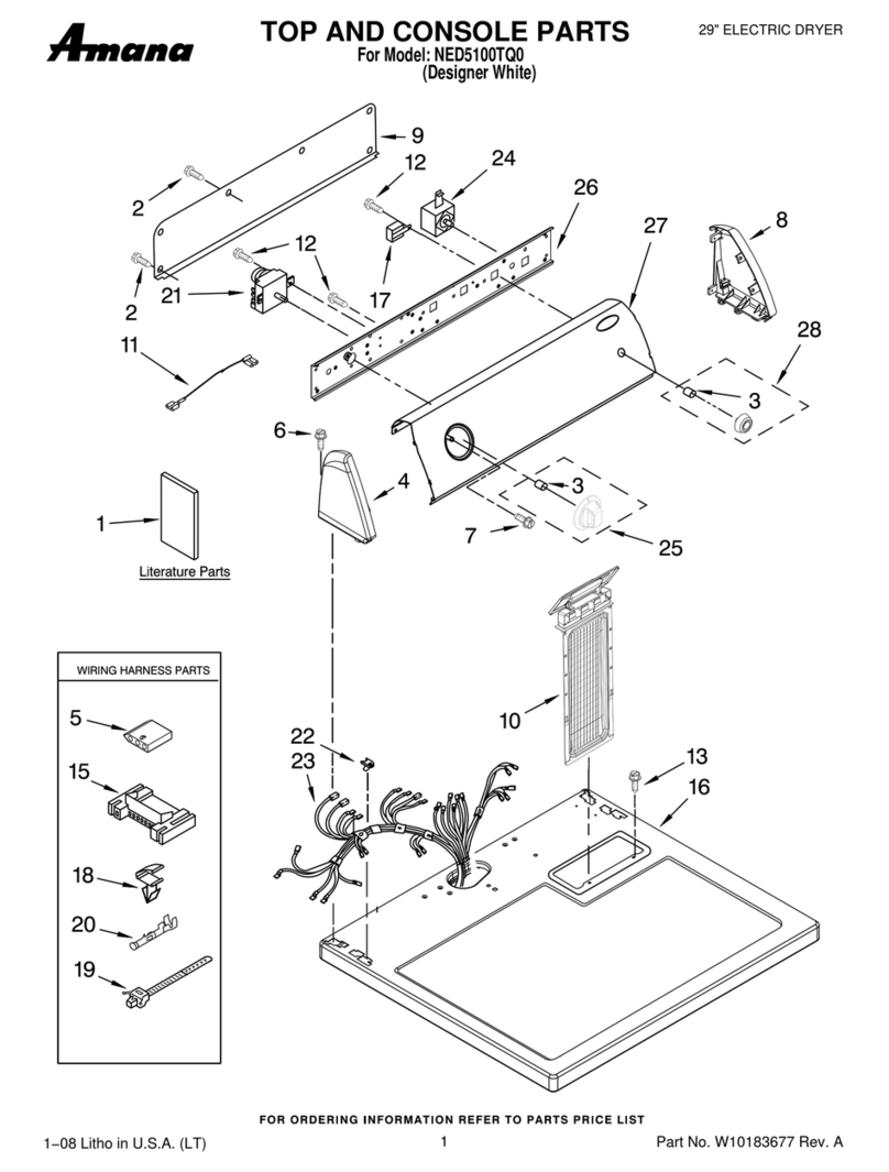
Amana NED5100TQ0 User manual

Amana
Amana NGD4500VQ0 User manual

Amana
Amana Home Laundry Dryers User manual
Amana
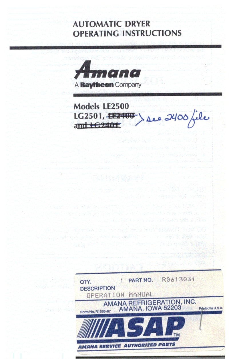
Amana LE2500 User manual
Amana
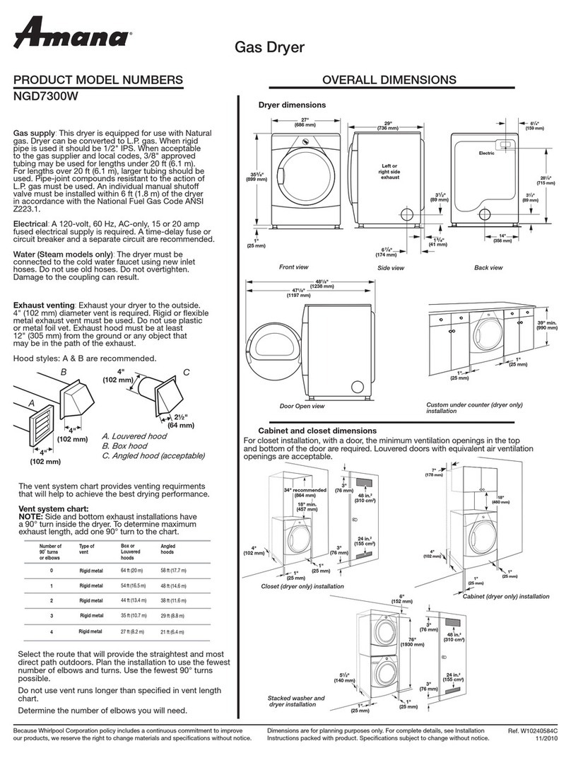
Amana NGD7300W User instructions
Amana
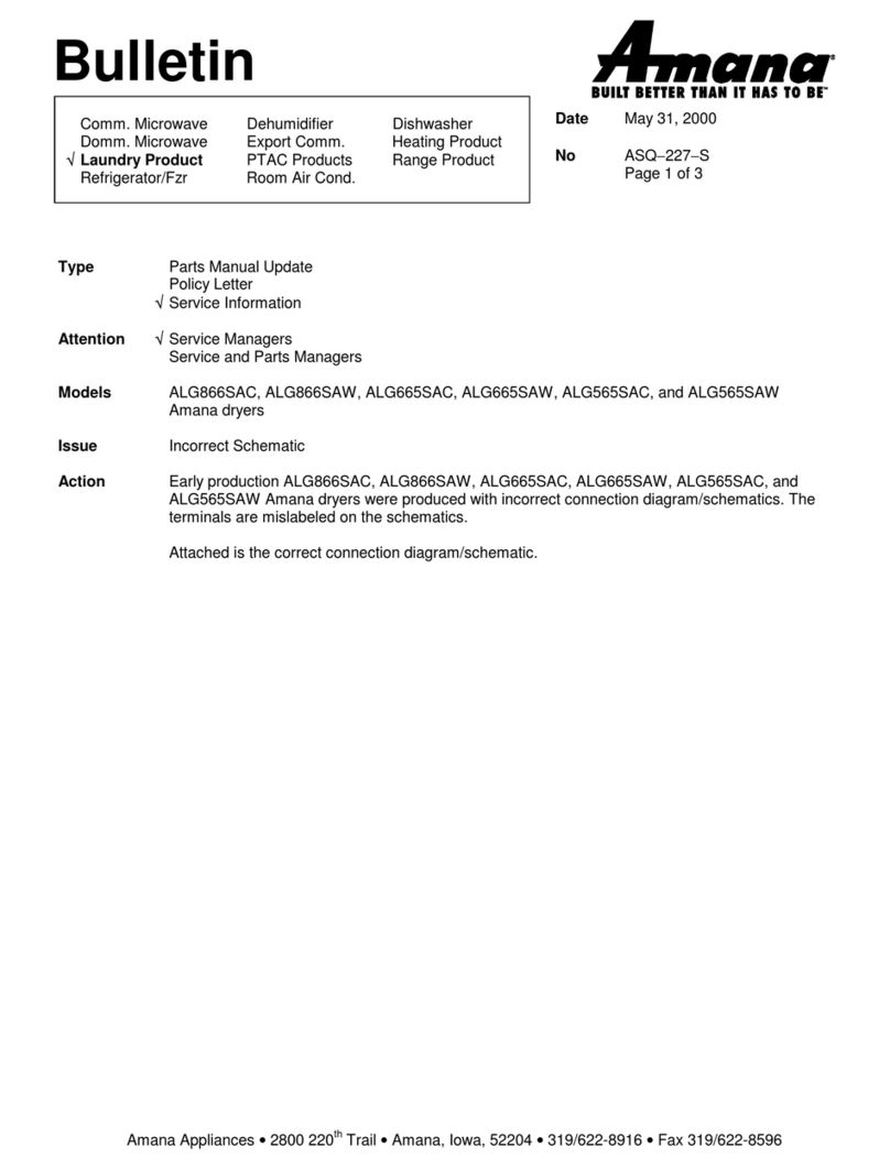
Amana ALG866SAC Manual
Amana
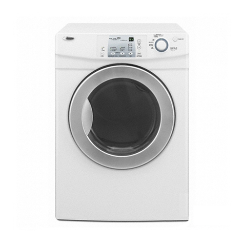
Amana NGD7200TW User manual
Amana
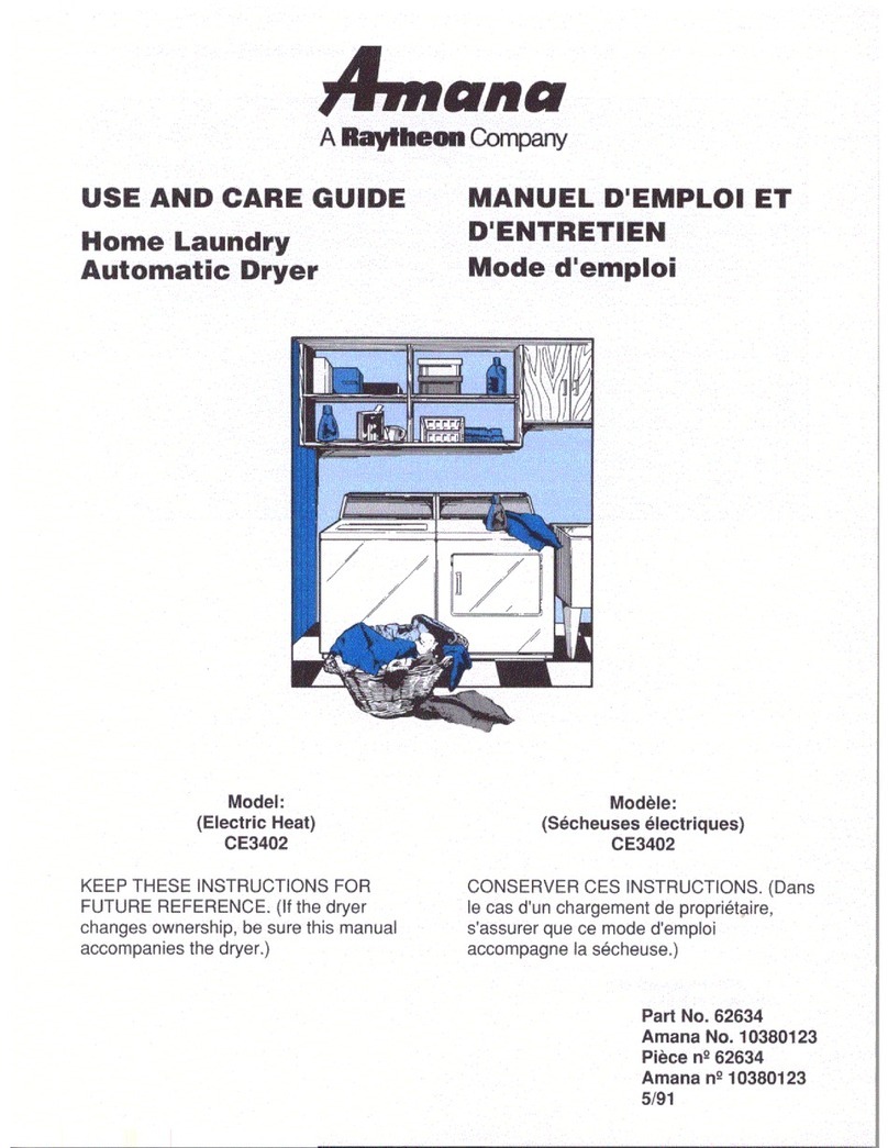
Amana CE3402 User manual
Amana
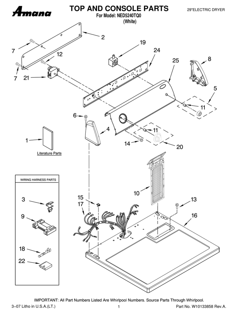
Amana NED5240TQ0 User manual

Amana
Amana LEA80AL User manual

Amana
Amana AAV1200AGW User manual
Amana
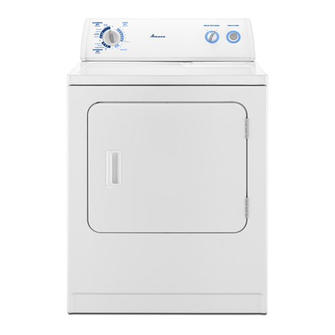
Amana NGD4800VQ1 User manual

Amana
Amana LE8367L2 User manual

Amana
Amana NED5800HW User manual
Amana
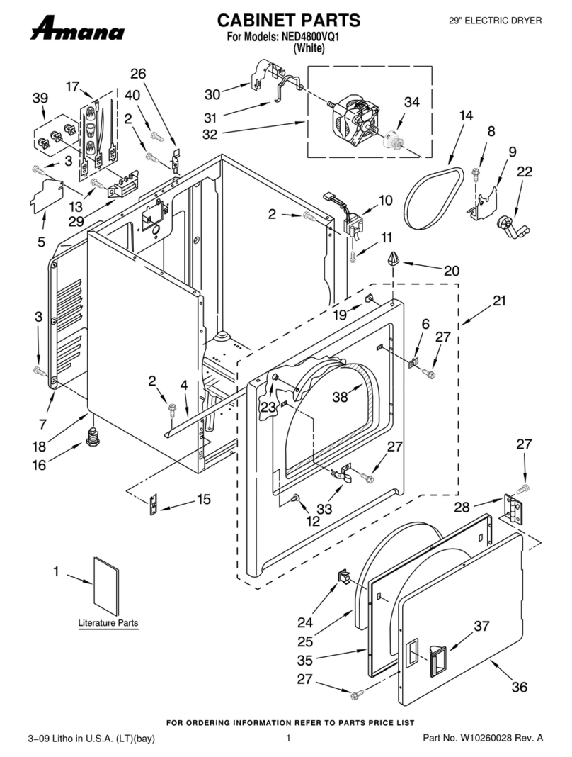
Amana NED4800VQ1 Troubleshooting guide

Amana
Amana LE7101WB User manual
Amana
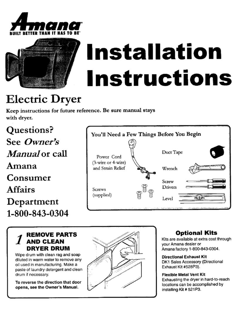
Amana 40086101 User manual

Amana
Amana NDE7800AZW User manual

Amana
Amana NGD4600Y User manual

Amana
Amana NTW4516FW User manual
Popular Dryer manuals by other brands

Asko
Asko T793C operating instructions

Kenmore
Kenmore 8041 - 5.8 cu. Ft. Capacity Electric Dryer installation instructions

Frigidaire
Frigidaire CAQE7077KW0 use & care

Bosch
Bosch WTX8HKM9SN User manual and installation instructions

Sharp
Sharp KD-NHH9S7GW2-PL user manual
Samsung
Samsung DV431AEPXAC user manual
