EnglishDeutsch
 logo
Brands
  1. Home
  2. •
  3. Brands
  4. •
  5. Amana
  6. •
  7. Ventilation Hood
  8. •
  9. Amana UXT5530AAS User manual

Amana UXT5530AAS User manual

Other manuals for UXT5530AAS

1

This manual suits for next models

10

Other Amana Ventilation Hood manuals

Amana UXT5230ADS Parts list manual

Amana

Amana UXT5230ADS Parts list manual

Amana HV303 Service manual

Amana

Amana HV303 Service manual

Amana UXW6530BS Manual

Amana

Amana UXW6530BS Manual

Amana UXT2036AY Product information sheet

Amana

Amana UXT2036AY Product information sheet

Amana UXG7360V Parts list manual

Amana

Amana UXG7360V Parts list manual

Amana UXL5430BS Manual

Amana

Amana UXL5430BS Manual

Amana UXT5236AYS User manual

Amana

Amana UXT5236AYS User manual

Amana UXG7360VDS Use and maintenance manual

Amana

Amana UXG7360VDS Use and maintenance manual

Amana UXT2030AYB Manual

Amana

Amana UXT2030AYB Manual

Amana UXT5430ADB User manual

Amana

Amana UXT5430ADB User manual

Amana UXT3030AYB Manual

Amana

Amana UXT3030AYB Manual

Amana UXT5530AAB Product information sheet

Amana

Amana UXT5530AAB Product information sheet

Amana UXI0600DYS User manual

Amana

Amana UXI0600DYS User manual

Amana HV303 User manual

Amana

Amana HV303 User manual

Amana UVL5430JSS Product information sheet

Amana

Amana UVL5430JSS Product information sheet

Amana UXT4030AY Parts list manual

Amana

Amana UXT4030AY Parts list manual

Amana UXT4230AYS Manual

Amana

Amana UXT4230AYS Manual

Amana UXT4236AYS User manual

Amana

Amana UXT4236AYS User manual

Amana UXB0600DYS User manual

Amana

Amana UXB0600DYS User manual

Amana UXT2030AY Parts list manual

Amana

Amana UXT2030AY Parts list manual

Amana UXT3030AY Parts list manual

Amana

Amana UXT3030AY Parts list manual

Amana UXD8630DYS Use and maintenance manual

Amana

Amana UXD8630DYS Use and maintenance manual

Amana HWR3021L User manual

Amana

Amana HWR3021L User manual

Amana UXT4030AYS Manual

Amana

Amana UXT4030AYS Manual

Popular Ventilation Hood manuals by other brands

Haier CXW-219-D67 null

Haier

Haier CXW-219-D67 null

emmeti RECUPA MED A-140 Installation and use manual

emmeti

emmeti RECUPA MED A-140 Installation and use manual

Nibe F135 user manual

Nibe

Nibe F135 user manual

Zephyr Spruce AK9834BS Use, care and installation guide

Zephyr

Zephyr Spruce AK9834BS Use, care and installation guide

Kuppersberg INTRO 60 Technical Passport

Kuppersberg

Kuppersberg INTRO 60 Technical Passport

Hisense MH6INBG manual

Hisense

Hisense MH6INBG manual

Miele DA 1255 Operating and installation instructions

Miele

Miele DA 1255 Operating and installation instructions

Broan 46000 Specification sheet

Broan

Broan 46000 Specification sheet

GE Profile PV977 Owner's Manual & Installation Instructions

GE

GE Profile PV977 Owner's Manual & Installation Instructions

FALMEC FFRIA24W5FS Instruction booklet

FALMEC

FALMEC FFRIA24W5FS Instruction booklet

Whirlpool RH2600XL-1 SERIES installation instructions

Whirlpool

Whirlpool RH2600XL-1 SERIES installation instructions

ETNA AV360RVS Instructions for use

ETNA

ETNA AV360RVS Instructions for use

JUNO JDF603E6 installation manual

JUNO

JUNO JDF603E6 installation manual

Miele DA 6708 D Operating and installation instructions

Miele

Miele DA 6708 D Operating and installation instructions

Tricity Bendix LE 150 Installation & operating instructions

Tricity Bendix

Tricity Bendix LE 150 Installation & operating instructions

AEG X68163BV1 user manual

AEG

AEG X68163BV1 user manual

AEG 125 D operating instructions

AEG

AEG 125 D operating instructions

Smeg KSEV97X instruction manual

Smeg

Smeg KSEV97X instruction manual

https://manuals.online logo
https://manuals.online logoBrands
  • About & Mission
  • Contact us
  • Privacy Policy
  • Terms and Conditions

Copyright 2026 Manuals.Online. All Rights Reserved.

Roof Venting Wall Venting
A. 6" (15.2 cm) or larger round
vent or a 3¹⁄₄" x 10" (8.3 x
25.4 cm) rectangular vent
through roof
B. Round vent: use 6" (15.2 cm)
or larger round damper
(purchased separately)
C. Round vent: use 3¹⁄₄" x 10"
(8.3 x 25.4 cm) to 6" (15.2 cm)
or larger diameter transition
piece
(purchased separately)
D. 24" (61.0 cm) - 30" (76.2 cm)
above electric cooking surface
27" (68.6 cm) - 30" (76.2 cm)
above gas cooking surface
E. Roof cap
A. 6" (15.2 cm) or larger round
vent or a 3¹⁄₄" x 10" (8.3 x
25.4 cm) rectangular vent
through the wall
B. Round vent: use 3¹⁄₄" x 10" (8.3
x 25.4 cm) to 6" (15.2 cm) or
larger diameter transition piece
(purchased separately)
C. 3¹⁄₄" x 10" (8.3 x 25.4 cm)
through the wall
D. 24" (61.0 cm) - 30" (76.2 cm)
above electric cooking surface
27" (68.6 cm) - 30" (76.2 cm)
above gas cooking surface
E. Wall cap
A
B
D
C
E
A
B
C
D
E
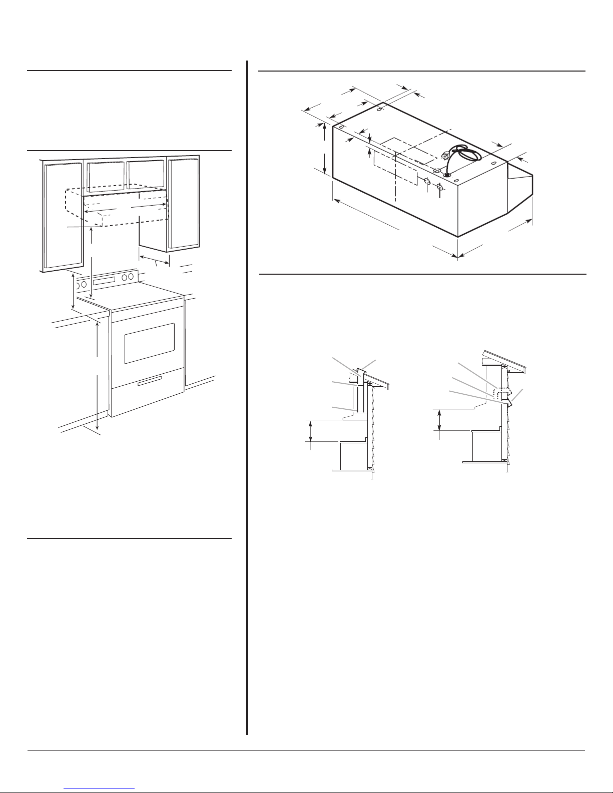
A. 18" (45.7 cm) min. clearance - upper cabinet to countertop
B. 24" (61.0 cm) min. for electric cooking surfaces
27" (68.6 cm) min. for gas cooking surfaces
30" (76.2 cm) suggested max. - bottom of range hood to
cooking surface
C. 30" (76.2 cm) or 36" (91.4 cm) min. cabinet opening width
D. 13" (33.0 cm) cabinet depth
E. 36" (91.4 cm) base cabinet height
A
B
C
D
E
Range Hood - 30" (76.2 cm) and 36" (91.4 cm)
PRODUCT MODEL NUMBERS
LOCATION REQUIREMENTS
UXT5530AA UXT5536AA
Because Whirlpool Corporation policy includes a continuous commitment to improve
our products, we reserve the right to change materials and specifications without notice. Dimensions are for planning purposes only. For complete details, see Installation
Instructions packed with product. Specifications subject to change without notice. Ref. W10274302B
10/22/09
CABINET OPENING DIMENSIONS
Electrical: A 120 volt, 60 Hz, AC only, 15- or 20-amp,
fused electrical circuit is required. A time-delay fuse or
circuit breaker is also recommended. It is recommended
that a separate circuit serving only this range hood be
provided.
IMPORTANT: Observe all governing codes and
ordinances.
● It is the installer’s responsibility to comply with
installation clearances specified on the model/serial
rating plate. The model/serial rating plate is located
inside the range hood on the left wall.
● Range hood location should be away from strong draft
areas, such as windows, doors and strong heating
vents.
For Mobile Home Installations
The installation of this range hood must conform to the
Manufactured Home Construction Safety Standards,
Title 24 CFR, Part 328 (formerly the Federal Standard
for Mobile Home Construction and Safety, title 24, HUD,
Part 280) or when such standard is not applicable, the
standard for Manufactured Home Installation 1982
(Manufactured Home Sites, Communities and Setups)
ANSI A225.1/NFPA 501A*, or latest edition, or with
local codes.
PRODUCT DIMENSIONS
29 ⁷⁄₈" (75.9 cm) - 30" (76.2 cm) model
35 ⁷⁄₈" (91.1 cm) - 36" (91.4 cm) model
1³⁄₁₆"
(3.0 cm)
2"
(5.1 cm)
12"
(30.5 cm)
7¹⁄₄"
(18.4 cm)
9"
(22.9 cm)
⁵⁄₈"
(1.6 cm)
⁵⁄₈"
(1.6 cm)
19
³⁄₄
"
(50.2 cm)
3" (7.6 cm) -
30" (76.2 cm) model
5³⁄₄" (14.6 cm) -
36" (91.4 cm) model
VENTING REQUIREMENTS
Vent system can terminate either through the roof or wall. Use 3¹⁄₄" x 10" (8.3 x 25.4 cm)
with a maximum vent length of 35 ft (10.7 m) or 6" (15.2 cm) or larger round vent with a
maximum length of 50 ft (15.2 m) for vent system.
NOTE: Flexible vent is not recommended. Flexible vent creates back pressure and air
turbulence that gently reduce performance.
Page 1 of 2
Because Whirlpool Corporation policy includes a continuous commitment to improve
our products, we reserve the right to change materials and specifications without notice. Dimensions are for planning purposes only. For complete details, see Installation
Instructions packed with product. Specifications subject to change without notice. Ref. W10274302B
10/22/09
Page 2 of 2
Calculating Vent System Length
To calculate the length of the system you need, add the equivalent feet
(meters) for each vent piece used in the system.
6" (15.2 cm) or Larger Round Vent System
Vent Piece Round
45°elbow 2.5 ft
(0.8 m)
90°elbow 5.0 ft
(1.5 m)
6" (15.2 cm) or larger 0.0 ft
wall cap (0.0 m)
3¹⁄₄" x 10" (8.3 cm x 25.4 cm) 4.5 ft
to 6" (15.2 cm) or larger (1.4 m)
3¹⁄₄" x 10" (8.3 cm x 25.4 cm) 5.0 ft
to 6" (15.2 cm) or larger (1.5 m)
90°elbow
Example vent system
Maximum Recommended Length = 50 ft (15.2 m)
1 - 90°elbow = 5.0 ft (1.5 m)
1 - wall cap = 0.0 ft (0.0 m)
8 ft (2.4 m) straight = 8.0 ft (2.4 m)
Length of 7" (17.8 cm) system = 13.0 ft (3.9 m)
Wall cap
90˚ elbow
2 ft (0.6 m)
6 ft (1.8 m)
3¹⁄₄" x 10" (8.3 cm x 25.4 cm) Vent System
Vent Piece Round
3¹⁄₄" x 10" (8.3 cm x 25.4 cm) 5.0 ft
90°elbow (1.5 m)
3¹⁄₄" x 10" (8.3 cm x 25.4 cm) 12.0 ft
flat elbow (3.7 m)
3¹⁄₄" x 10" (8.3 cm x 25.4 cm) 0.0 ft
wall cap (0.0 m)
Example vent system
Maximum Recommended Length = 35 ft (10.7 m)
1 - 90°elbow = 5.0 ft (1.5 m)
8 ft (2.4 m) straight = 8.0 ft (2.4 m)
1 - wall cap = 0.0 ft (0.0 m)
Length of 3¹⁄₄" x 10" (8.3 cm x 25.4 cm) = 13.0 ft (3.9 m)
system
Wall cap
3¹⁄₄" x 10"
(8.3 x 25.4 cm)
elbow
2 ft
(0.6 m)
6 ft (1.8 m)