Amazone AMASET+ User manual

Operator's manual
az
AMASET+
Switch box
MG2047
BAG0007.4
08.16
Printed in Germany
Before starting operation
carefully re
ad and adhere to
this operator's manual.
Keep for other users
!
en

Preface
2
AMASET+ BAG0007.4
08.16
Reading the instruction
manual and to adhere to it should not appear to
be inconvenient and superfluous as it is not
enough to hear from others and to realise that a
machine is good, to buy it and to believe that now
everything would work by itself. The person con-
cerned would not only harm himself but also
make the mistake of blaming the machine for the
reason of a possible failure instead of himself. In
order to ensure a good success one should go into
the mind of a thing or make himself familiar with
every part of the machine and to get acquainted
with its handling. Only this way, you would be
satisfied both with the machine as also with
yourself. To achieve this is the purpose of this op-
erator's manual.
Leipzig-Plagwitz 1872.

Contents
AMASET+
BAG0007.4 08.16
3
1User advice...................................................................................................4
1.1 Purpose of the document.........................................................................................................4
1.2 Information about directions in this operator's manual............................................................4
1.3 Illustrations used......................................................................................................................4
2General safety advice..................................................................................5
2.1 Illustration of safety advice.......................................................................................................5
3Product description.....................................................................................6
3.1 Overview..................................................................................................................................6
3.2 Designated use of the machine ...............................................................................................7
4Assembly and function ...............................................................................8
4.1 Display / Indications.................................................................................................................8
4.2 Description of the switches......................................................................................................8
4.3 Description of the keys.............................................................................................................9
5Putting into operation................................................................................10
5.1 Initial operation.......................................................................................................................10
5.2 AMASET+- connection.....................................................................................................10
6Settings.......................................................................................................11
6.1 Setting the equal pressure valve chest..................................................................................11
7Operation of the machine..........................................................................13
8Faults..........................................................................................................15
9Maintenance, repair and care ...................................................................15

User advice
4
AMASET+ BAG0007.4
08.16
1 User advice
The chapter "User advice" provides information for dealing with the
operator's manual
1.1 Purpose of the document
The present operator's manual
•describes the operation and the maintenance for the machine.
•gives important hints for a safety conscious and efficient opera-
tion with the machine.
•is part of the implement and should be kept so that it is always to
hand on the machine or in the towing vehicle.
•should be kept for future use.
1.2 Information about directions in this operator's manual
All information about direction in this operator's manual are to be un-
derstood in direction of travel.
1.3 Illustrations used
Operational action and react
The steps of operation to be carried out by the operational staff are
described in a numbered list. Adhere to the sequence of the steps.
The reactions on the individual operational step are marked with an
arrow. Example:
1. Operational action step 1
→Reaction of the machine on operational action step 1
2. Operational action step 2
Enumerations
Enumerations without indispensable sequence are described as a list
with enumeration items. Example:
•Item 1
•Item 2
Position figures in illustrations
Figures in round brackets refer to position figures in illustrations. The
first figure refers to the illustration, the second figure refers to the item
number in the illustration.
Example (Fig. 3/6)
•Figure 3
•Item 6

General safety advice
AMASET+
BAG0007.4 08.16
5
2 General safety advice
2.1 Illustration of safety advice
The safety advice is identified by a symbol and a warning. The warn-
ing describes the seriousness of the threatened danger. The individu-
al symbols have the following meaning:
DANGER
Immediately imminent danger for life and health of persons (se-
vere injuries or death).
Not adhering to this advice will cause severe damage to health
up to life threatening injuries.
WARNING
Possibly danger for life and health of persons.
Not adhering to these hints may cause severe adverse health
effects up to life threatening injuries.
CAUTION
Possibly dangerous situation (slight injuries, material damage).
Not adhering to these hints may cause slight injuries or material
damage.
IMPORTANT
Obligation of particular behaviour or action for the appropriate
handling of the machine.
Not adhering to these hints may cause trouble on the machine or
the environment.
HINT
Hint for use and particularly useful information.
These hints will help you to optimally make use of the functions
on your machine.

Product description
6
AMASET+ BAG0007.4
08.16
3 Product description
This chapter
●provides you with a comprehensive survey about the design of
the AMASET+.
•provides the descriptions of the individual components and parts
3.1 Overview
Fig. 1
(1) Key ON / OFF
(2) Indication spraying pressure
(3) Key optional equipment with light:
οEnd nozzle switching right hand side
οBorder spreading nozzle switching
right hand side
οOne side folding right hand side
(4) Key optional equipment with light:
οEnd nozzle switching left hand side
οBorder spreading nozzle switching left
hand side
οOne side folding left hand side
(5) Switching on / off the switch spraying op-
eration
(6) Indication tilt adjustment
(7) Indication locking of the swing compensa-
tion
(8)
Key hydraulic changeover folding the booms
– tilt adjustment - with light
(9) Switch for setting the spray pressure
(10)
Switch for switching on / off boom part width
secsions – with light

Product description
AMASET+
BAG0007.4 08.16
7
3.2 Designated use of the machine
The switch box AMASET+
●is designed as indicating, monitoring and control device for
AMAZONE UF01 field sprayers with equal pressure valve
chest.
The declined use also includes:
•The declined use also includes:
•observing all hints in this operator's manual.
•adhering the service and maintenance work.
•the exclusive use of AMAZONE original - spare parts.
Other use than that stipulated is prohibited and is no longer consid-
ered as designed use.
For damage resulting from not designed use
•the operator himself will carry the full risk,
•the manufacturer will not accept any responsibility.

Assembly and function
8
AMASET+ BAG0007.4
08.16
4 Assembly and function
The following chapter informs you about the assembly of
AMASET+ and the functions of the individual components.
4.1 Display / Indications
•Indication spraying pressure
Shows the spraying pressure during operation of
the field sprayer.
•Indication tilt adjustment
οThe boom tilting is indicated with the
aid of a red light.
οThe average position is shown in
green.
οNo tilt adjustment available:
Light emitting diode outermost right
hand side lights up.
•Indication locking of swing compensation
The light indicates that the swing compensation
is locked.
4.2 Description of the switches
•Switch for setting the spray pressure
ο+- increasing the spray pressure.
ο-- reducing the spray pressure.
•Switching on / off the switch spraying op-
eration
Opening (1), closing (2) all boom part width sec-
tions.

Assembly and function
AMASET+
BAG0007.4 08.16
9
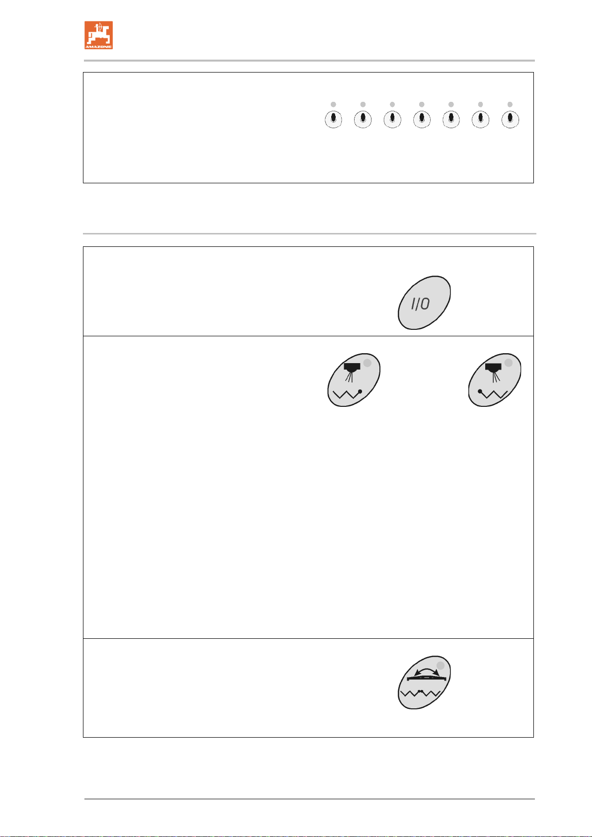
•Switch for switching on / off the boom part
width sections. The number of switches is
equal to that of the boom part width sec-
tions.
Left hand switch – boom part width section
outermost left hand side off / on.
Right hand switch – boom part width section
outermost right hand side off / on.
4.3 Description of the keys
•Key On / OFF
Switching on and off the AMASET+
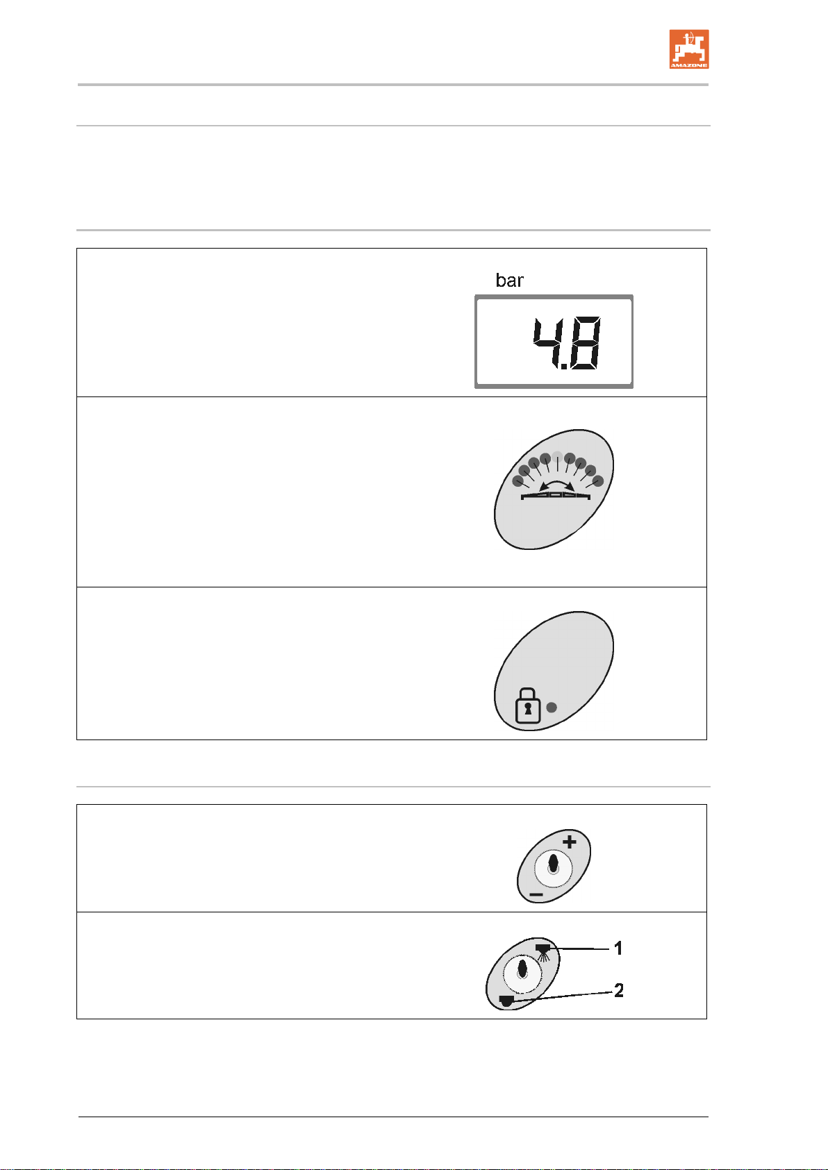
After switching on the pressure indication lights
up and AMASET+ is ready for operation.
•Keys optional equipment: Left and right
hand side
These keys are available for one of the following
4 possibilities:
οEnd nozzle switching
When the end nozzle switching is
switched on (green indicator light) the
outer boom part width section is re-
duced each by 1, 2 or 3 nozzles.
οBorder spreading nozzles
When the end nozzle switching is
switched on (green indicator light) the
outer nozzle is switched off and the
border spreading nozzle is switched
on.
οOne side folding
When the boom is folded down the
one side folding can be switched on.
Control lamp illuminates:
Boom side is blocked.
Control lamp does not illuminate:
Boom side can be folded.
οKey not covered.
•Key hydraulic changeover folding of the
boom – tilt adjustment
For coupling the hydraulic functions connect tilt
adjustment and folding to a double acting control
valve on the tractor.
The light indicates when the tilt adjustment is
active.

Putting into operation
10
AMASET+ BAG0007.4
08.16
5 Putting into operation
In his chapter you will find information for putting your machine into
operation.
DANGER
Before putting the machine into operation ensure that the opera-
tor has read and understood the operator's manual.
DANGER
Please also refer to the operator's manual for the field sprayer!.
5.1 Initial operation
•Setting the equal pressure valve chest (see Seite 11)
5.2 AMASET+- connection
•Connect the implement plug on AMASET+.

Settings
AMASET+
BAG0007.4 08.16
11
6 Settings
6.1 Setting the equal pressure valve chest
Setting the equal pressure valve chest
•
once a year.
•
at every nozzle change.
Hint!
The equal pressure valve chest can be adjusted for 5 different
nozzles, according to the 5 colours on the pre-selection disks.
In order to get a nozzle to work the related colour of the disk
should point towards the left hand side.
1. Fill the mounted sprayer with approx. 400 l
of water.
2. Fold down the boom and drive the pump
with the service rev. speed (e.g. 450
R.P.M.).
3. Switch on AMASET+(Fig. 2/1).
4. Switch on spraying operation
water escapes from the nozzles.
5. Set agitation intensity 1 on the step tap.
6. (Fig. 2/3) actuate + /- until the
spray pressure indicator shows a spray
pressure of 4 bar.
7. The coloured icons on the equal pressure
pre-selection disks (Fig. 3/1) correspond to
the colour of the relevant spraying nozzle.
The coloured icon must point to the left
hand side (Fig. 4/1).
Fig.
2
Fig.
3

Settings
12
AMASET+ BAG0007.4
08.16
8. Pre-adjust the equal pressure valve chest
via the stud screw (Fig. 4/2).
οClose one boom part width section via
a boom part width section switch (Fig.
2/4). The adjusted spray pressure
changes on the spray pressure indica-
tion.
οTurn the stud screw (Fig. 4/2) related
to this boom part width section valve
until the spray pressure indication
shows again the spray pressure of
4 bar. Then open this boom part width
section.
οSet the equal pressure valve chests of
the other boom part width section
valves in the same way.
9. After adjustment close all boom part width
sections. The indicated pressure should not
also be 4 bar. If this is not the case, repeat
the adjustment on the equal pressure valve
chest.
10. After the pre-adjustment of the equal pres-
sure for the relevant nozzle, the equal pres-
sure can be re-established after every noz-
zle change by turning the equal pressure
pre-select disc to the related nozzle colour.
For this slacken the thumb nut (Fig. 4/3),
pull out the equal pressure pre-select disc
and turn – retighten the thumb nut.
Fig.
4

Operation of the machine
AMASET+
BAG0007.4 08.16
13
7 Operation of the machine
DANGER
•
When starting to operate the machine observe the opera-
tor's manual for the field sprayer.
•
When operating the machine observe the chapter "Safety
advice for the operator", page 5.
1. Prepare the spray cocktail as prescribed according to the in-
structions of the plant protective agent manufacturer and agitate.
2. Set the reversing taps on the control panel to spraying.
3. Read off the tractor meter the correct tractor gear for a forward
speed from 6 up to max. 8 km/h. Use the throttle hand lever for
setting the constant tractor engine rev. speed considering the
pump drive rev. speed (min 350 R.P.M: and max. 550 R.P.M.).
4. Switch on AMASET+.
5. Lifting the sprayer boom until the transport securing device un-
locks via the tractor control valve yellow.
6. Folding down the sprayer boom via the tractor control valve
green .
Beforehand actuate the selection switch if applicable.
7. Setting the spraying height via tractor control valve hose mark
yellow.
8. Adjusting the boom tilting via the tractor control valve
natural.
Beforehand actuate the selection switch if applicable.
9. Setting the spray rate via the spray pressure!
actuate + /- until the spray pressure indication shows
the required spray pressure according to the spray rate table.
10. Select the suited tractor gear and drive off
Maintain the selected tractor gear during the spraying operation.

Operation of the machine
14
AMASET+ BAG0007.4
08.16
11. Switching on spraying operation and spraying the area.
12. Switching off spraying operation.
13. Align the sprayer boom horizontally naturaland fold in green via
control valve on the tractor.
14. Via control valve on the tractor yellow lower the sprayer boom
until the transport securing device locks.
Metering automatics:
Within one tractor gear the forward speed related metering is
achieved. That means, if the tractor engine rev. speed drops, e.g.
due to a gradient, in addition to the forward speed also the trac-
tor universal joint shaft rev. speed and thus the pump drive re.
Speed drops in the same ratio. Hereby also the pump capacity
changes in the same ratio and the desired spread rate [l/ha] is
maintained – within one tractor gear. At the same time also the
adjusted spray pressure changes.
WARNING
To achieve the optimum effect of the spray cocktail to be spread
and to avoid unnecessary environmental harm the spray pres-
sure for the relevant nozzle has to be maintained within the rele-
vant pressure range (see spray rate table).
Example:
When the adjusted spray pressure is, for example, 3,2 bar, spray
pressures of between 2,4 and 4,0 bar are allowed. Never ever leave
the permissible pressure range of the installed nozzles.
When increasing the forward speed do not exceed the maximum
permissible pump drive rev. speed of 550 R.P.M.!
WARNING
Bigger deviations of the spray pressure would cause an unde-
sired change of droplet size of the spray cocktail!
Switch on and off the sprayer boom only whilst driving.
•During spraying operation accurately maintain the pre-selected
tractor gear and the agitation intensity, as otherwise deviations
from the desired spray rate would result.
•During the spraying operation continuously check the spray
cocktail consumption in relation to the treated area.
•In case of a considerable drop of the spray pressure the tank is
empty. If in case of unchanged conditions the spray pressure
drops, either the suction or the pressure filter is blocked.
•All spray rates l/ha in the spray rate table are valid for water.
Multiply the corresponding values for AUS by 0.88 and for NP
solutions by 0.85.

Faults
AMASET+
BAG0007.4 08.16
15
8 Faults
Fault
Cause
Remedy
Spray rate is not correct
Pressure meter is defective
Contact an authorised workshop
Nozzles are worn
Exchange the nozzles
Spray pressure adjustment is not
possible
Power supply is interrupted
Check the power supply
Switching boom part width sec-
tions is not possible
Power supply is interrupted
Check the power supply
Boom part width section valve
defective
Exchange the voom part width
section valve
No correct switching
•of the end nozzles
•of the border nozzles
•one side folding
•changing over from folding
to tilt adjustment
Solenoid valves dirty
Clean solenoid valves
9 Maintenance, repair and care
Once a year: Setting the equal pressure valve chest (see Seite 11)

H. DREYER GmbH & Co.
KG
Postfach 51
D
-49202 Hasbergen-Gaste
Germany
Tel.: + 49 (0) 5405 501-0
e-mail: amazone@amazone.de
http:// www.amazone.de
Branch factories in: D-27794 Hude •D-04249 Leipzig
•F-57602 Forbach •Subsidiaries in England and France
Factories for mineral fertiliser spreaders, field sprayers, seed drills, soil tillage implements,
multi purpose storing halls and municipal implements
Table of contents
Popular Switch manuals by other brands

Upvel
Upvel UP-319GEW Quick installation guide

3Com
3Com OfficeConnect WX1200 Command reference

TW Electronic Components
TW Electronic Components LP444s user manual

Sigma
Sigma SLX series Operator's manual

ZyXEL Communications
ZyXEL Communications XGS3600 Series manual

Samson
Samson 3738-20 Mounting and operating instructions

ZyXEL Communications
ZyXEL Communications PMG5318-B20B quick start guide

Belkin
Belkin FIREWIRE 1394 user manual

steute
steute Ex 14 Mounting and wiring instructions

H3C
H3C S5500-EI series quick start

Moxa Technologies
Moxa Technologies ToughNet TN-4500A Series Quick installation guide

STI
STI CMCP423VTA user guide