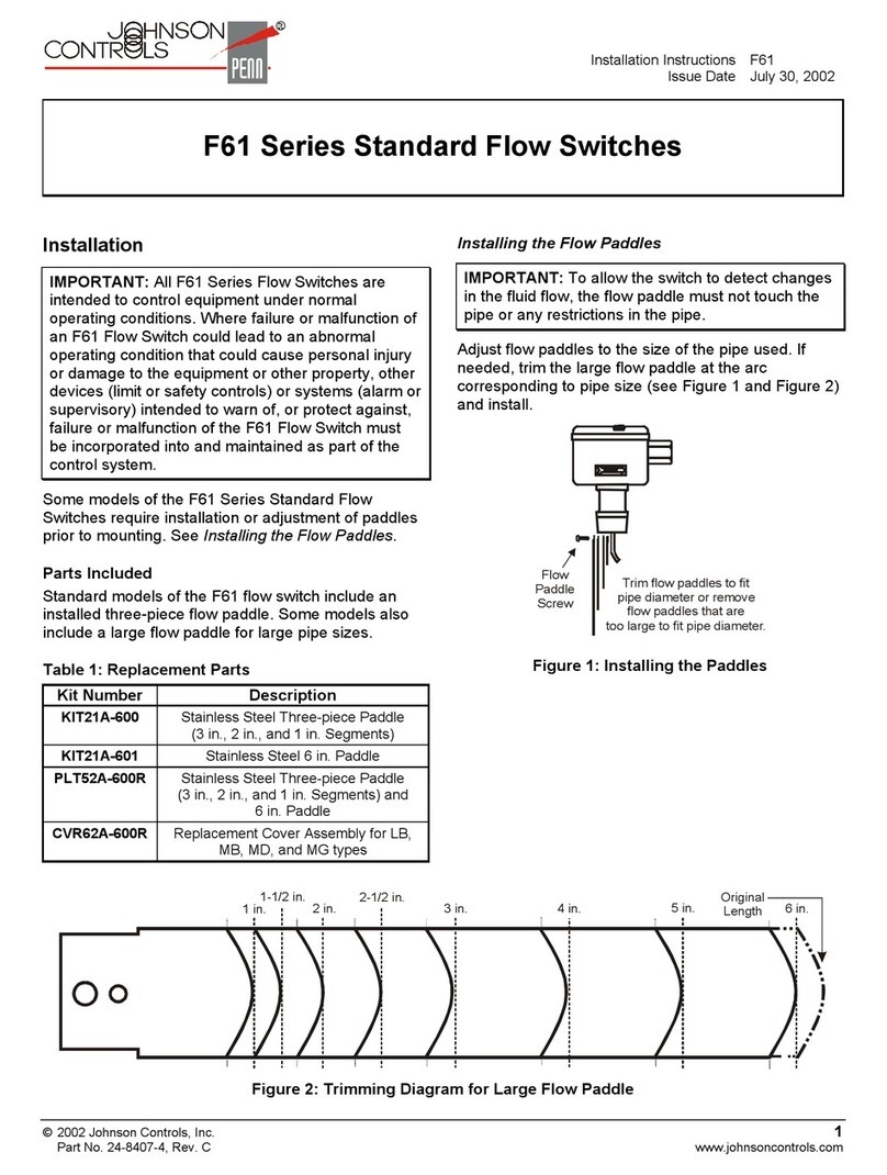
Installation Instruction FS80-C
Issue Date 0912
The performance specifications conform to acceptable industry standard. For application to conditions beyond these specifications, consult the local Johnson Controls office. Johnson Controls,
Inc., shall not be liable for damages resulting from misapplication or misuse of its products. ©2009 Johnson Controls, Inc.
www.johnsoncontrols.com
1
FS80-C Flow Switch
Application
1) FS80-C Flow Switch responds to fluid flow in lines carrying water ethylene
glycol or other non-hazardous fluids.
2) FS80-C Flow Switch use a variety of paddle sizes to respond to fluid flow
rates in applications with pipe sizes greater than 1-inch trade size.
3) Single-Pole Double-Throw (SPDT) flow switch that can be wired to energize
one device and de-energize another device powered from the same source
when liquid flow either exceeds or drop below the set flow rates.
4) FS80-C use with fluid pressures up to 1.5MPa.
5) Maximum Velocity: 3m/sec.
6) Fluid temperature range: -25
℃
to 110
℃
fluid temperatures need above
ambient dew point; Ambient temperature range: -20
℃
to 60
℃
7) FS80-C Flow Switch with IP55 enclosure.
ELECTRICAL RATINGS
Electrical
rating
Horse
power
(HP)
Full Load
Amperes
(A)
Locked
Rotor
Amperes(A)
Non-
inductive
Amperes(A)
Pilot Duty
110VAC 1 16 96 16
220VAC 1 8 48 16
125VA at 24
~
277VAC
PERATI N
The SPDT switch on the FS80-C has color-coded terminals. Red is common
and closed to Blue upon flow increase and to Yellow upon flow decrease. See
Figure 1 and Table 1 for switch action and flow rates.
Fig.1 Switch Action
INSTALLATI N AND WIRING
Adjusting the Flow Switch Paddle
FS80-C Flow Switch comes with 4-piece paddle (1 in. 2 in . 3 in. and 6 in.
segments). Adjust the paddle to the size of the pipe in which it will be
installed. If needed use the template (see Figure 5) and trim the large
paddle at the arc corresponding to pipe size and install.
Example, if 3” pipe is used, Install 1” , 2” and 3” segments (see Figure 2), if
1-1/2 pipe is used, trim the 2” paddle to the pipe size or use the 1” paddle
segment.
Figure 2 Paddle Installation Example
Mount the FS80-C in a section of pipe where there is a straight run of at least
five pipe diameters on each side of the Flow Switch. See Figure 3.
Figure 3 Typical Installation
The switch should be mounted so the terminals or wire leads are easily
accessible for wiring.
Note
:
These flow switch must not be subjected to water hammer. If a fast-closing
valve is located downstream of the flow switch a suitable water hammer arrester
must be used. See figure 4.
Figure 4 Arrester Location Schematic
Mount the flow switch in a standard 1 in.x 1 in.x 1 in. tee for 1 in. pipe
installation. Use a reducing tee for larger sizes of pipe to keep the flow switch
close to the pipe and provide adequate paddle length in th flow stream.
Example: Use a 2 in.x 2 in.x 1 in. tee for a 2 in. pipe. If a standard 2 in.x 2 in.x 2 in.
tee is used install a face or hex bushing in the top opening to reduce it to 1 in.
Screw the flow switch in position so the flat of the paddle is at a right angle to
the flow. The arrow on the side of the case must point in the direction of the
flow.
FS80-C flow switch may be mounted in a horizontal pipe line or a vertical
pipe line with upward liquid flow. It is not recommended for installations
where flow is downward. When mounted in a vertical pipe with upward flow
the switch will trip at a slightly higher flow than shown in table 1 Typical Flo
Rates due to the effect of gravity on the switch mechanism.
Wiring
IMP RTANT
:
Do not use FS80-C on systems with flow velocity greater
IMP RTANT
:
::
:
FS80-C Flow Switch is designed for use only as operating
controls. Where an operating control failure would result in personal
injury and/or loss of property, it is the responsibility of the installer to
add devices (safety, limit controls) that protect against, or systems
(alarm. Supervisory systems) that warn of, control failure.
WARNING: Shock hazard
Disconnect the power supply before the wiring connections are made
electrical shock or damage to the equipment
IMP RTANT:To allow the switch to detect changes in the flow condition,
the paddle must not touch the pipe or any restrictions in the pipe.
CAUTI N: Equipment damage hazard.
To avoid damaging the switch, do not tighten the switch to the tee by
grasping the switch enclosure. Use only the wrench flats provided (see
Figure 6).

