manuals.online logo
Brands
  1. Home
  2. •
  3. Brands
  4. •
  5. Ambassade de Bourgogne
  6. •
  7. Grill
  8. •
  9. Ambassade de Bourgogne CSG 410 SLR Configuration guide

Ambassade de Bourgogne CSG 410 SLR Configuration guide

Other Ambassade de Bourgogne Grill manuals

Ambassade de Bourgogne CME 410 GR User manual

Ambassade de Bourgogne

Ambassade de Bourgogne CME 410 GR User manual

Ambassade de Bourgogne CSG 410 CK User manual

Ambassade de Bourgogne

Ambassade de Bourgogne CSG 410 CK User manual

Ambassade de Bourgogne CMG 410 CK User manual

Ambassade de Bourgogne

Ambassade de Bourgogne CMG 410 CK User manual

Ambassade de Bourgogne CMG 610 SRK User manual

Ambassade de Bourgogne

Ambassade de Bourgogne CMG 610 SRK User manual

Ambassade de Bourgogne CSG 410 GL User manual

Ambassade de Bourgogne

Ambassade de Bourgogne CSG 410 GL User manual

Ambassade de Bourgogne CSE 410 M User manual

Ambassade de Bourgogne

Ambassade de Bourgogne CSE 410 M User manual

Ambassade de Bourgogne CSG 610 SRK User manual

Ambassade de Bourgogne

Ambassade de Bourgogne CSG 610 SRK User manual

Popular Grill manuals by other brands

LMS BBQ08873P owner's manual

LMS

LMS BBQ08873P owner's manual

Cookworks LW-8010A Care & instruction manual

Cookworks

Cookworks LW-8010A Care & instruction manual

Campingaz CV Instructions for use

Campingaz

Campingaz CV Instructions for use

Metos XBL Series Installation and operation manual

Metos

Metos XBL Series Installation and operation manual

Fiesta ET34567 Use and care instructions

Fiesta

Fiesta ET34567 Use and care instructions

Mayer Barbecue BRENNA MKG-318A BASIC Assembly instructions

Mayer Barbecue

Mayer Barbecue BRENNA MKG-318A BASIC Assembly instructions

Landmann Avalon PTS Plus 5.1 Plus 12122 Assembly and operating manual

Landmann

Landmann Avalon PTS Plus 5.1 Plus 12122 Assembly and operating manual

Kenyon B70200 owner's manual

Kenyon

Kenyon B70200 owner's manual

Better Homes and Gardens GBC1486W owner's manual

Better Homes and Gardens

Better Homes and Gardens GBC1486W owner's manual

Orbegozo GR 2300 instruction manual

Orbegozo

Orbegozo GR 2300 instruction manual

bora PT11 Operating and installation instructions

bora

bora PT11 Operating and installation instructions

Klarstein 10031664 manual

Klarstein

Klarstein 10031664 manual

Garland MWE3W Installation and operation manual

Garland

Garland MWE3W Installation and operation manual

Char-Broil 463722714 Product guide

Char-Broil

Char-Broil 463722714 Product guide

MPM MOP-03 user manual

MPM

MPM MOP-03 user manual

Kenmore 415.16123800 Use and care guide

Kenmore

Kenmore 415.16123800 Use and care guide

Tucker Barbecues GTR Series Assembly, installation and operating instructions

Tucker Barbecues

Tucker Barbecues GTR Series Assembly, installation and operating instructions

Monogram ZGG540NCP1SS owner's manual

Monogram

Monogram ZGG540NCP1SS owner's manual

manuals.online logo
manuals.online logoBrands
  • About & Mission
  • Contact us
  • Privacy Policy
  • Terms and Conditions

Copyright 2025 Manuals.Online. All Rights Reserved.

Date de mise à jour : 29/09/2009 - FT 98a - FR / GB / NL- Révision 04 Page 1 sur 15
« CSG 410 SLR »
MANUEL GENERAL
GENERAL MANUAL
ALGEMENE HANDLEIDING
AMBASSADE
DE BOURGOGNE
Date de mise à jour : 29/09/2009 - FT 98a - FR / GB / NL- Révision 04 Page 2 sur 15
AMBASSADE
DE BOURGOGNE
CSG 410 SLR
SOCIETE INDUSTRIELLE DE
LACANCHE
Tél. :03.80.90.35.00 - Fax : 03.80.84.24.92
Société anonyme au capital de 150.000 €
Adhérent SYNEG
Raccordement gaz
Gas connection
Gasaansluiting
Raccordement électrique
Electric connection
Elektrische aansluiting
410
338
400
410
300
650
85
408
50
50
200
Date de mise à jour : 29/09/2009 - FT 98a - FR / GB / NL- Révision 04 Page 3 sur 15
FR PRESSIONS - CONSOMMATIONS GB PRESSURES - CONSUMPTION NL DRUCWAARDEN-
ENERGIEVERBRUIK
Tableau 3, annexe 2 – Table 3, appendix 2 – Tabel 3, bijlage 2.
RACCORDEMENT GAZ / GAS CONNECTION / GASAANSLUITING
Tube Ø 15/21, filetage 1/2" gaz sur raccord femelle / Tube Ø 15/21, 1/2" gas thread, on female coupling.
Leiding Ø 15/21, schroefdraad 1/2" voor gasaansluiting, met vrl. koppeling.
RACCORDEMENT ELECTRIQUE / ELECTRIC CONNECTION / ELECTRISCHE
AANSLUITING
Sur bornier au dos de l’appareil / On terminal block at the rear of the appliance / Op klemblok aan de achterkant van het
apparaat.
FR DONNES TECHNIQUES GB TECHNICAL DATA
NL TECHNISCHE GEGEVENS
Brûleurs / Burners / Branders 2
Plaque / Plate / Plaat : Dimensions (L x P) /
Dimensions ( L x W) / Afmetigen (B x D) 367 x 495 mm
Trois versions
Three types
Drie uitvoeringen
Semi rainurée
Half-ribbed, half-plain Gegroefde helft
Acier / Steel / Staal SLR
Allumage / Ignition / Ontsteking Allumeurélectrique/ Ignition unit / Ontsteking
Surveillance de flamme / Fire control / Vlamkontrole Thermocouple / Thermokoppel
Puissance / Rating / Kapaciteit 6 kW ( 2 x 3 kW )
FR OPTIONS GB OPTIONS NL OPTIES
Porte / Door / Deur - Echelles / Laders / Ladders
FR ACCESSOIRES GB ACCESSORIES NL ACCESSOIRES
Tiroir récupérateur / Collecting drawer / Opvanglade
Date de mise à jour : 29/09/2009 - FT 98a - FR / GB / NL- Révision 04 Page 4 sur 15
« CSG 410 SLR »
MANUEL D’INSTALLATION
INSTALLER’S MANUAL
INSTALLATIEHANDLEIDING
AMBASSADE
DE BOURGOGNE
FR L’installation doit se faire selon les règles de l’art conformément aux instructions contenues dans
cette notice et les règlements en vigueur dans le pays d’installation.
Ce manuel sera remis à l’utilisateur après installation.
GB Appliances must be installed in a workmanlike manner in accordance with the instructions in this
manual and locally applicable regulations.
This manual will be handed over to the user after installation.
NL De apparaten moeten volgens de in het betreffende land geldende wetten en voorschriften worden
geïnstalleerd, met strikte inachtneming van de instrukties uit deze handleiding.
Deze handleiding moet na het installeren aan de gebruiker overhandigd worden.
Date de mise à jour : 29/09/2009 - FT 98a - FR / GB / NL- Révision 04 Page 5 sur 15
IMPLANTATION / SITING
PLAATSING
FR Installer impérativement sous une hotte d’extraction.
Si cet appareil doit être mis en place près d’un mur, d’une cloison, d’un meuble, de bordures décoratives. Il
est recommandé que ceux -ci soient faits d’un matériau non combustible. Si ce n’est pas le cas, ils doivent
être recouverts d’un matériau approprié, bon isolant thermique non combustible. Une attention toute spéciale
étant accordée aux réglementations de prévention des incendies.
GB Must be installed under an extractor hood.
Do not install this unit near combustible walls, partitions, pieces of furniture or decorative material unless
these are covered with adequate thermal insulation of the noncombustible type. Making sure the resulting
installation meets local fire regulations.
NL Moet verplicht onder een afzuigkap worden geplaatst.
Dit kooktoestel mag uitsluitend in de nabijheid van brandbare muren, scheidingswanden, keukenmeubels,
sier- of ander materialen worden geplaatst wanneer deze bedekt dan wel overtrokken zijn met brandwerend
isolatiemateriaal. De aldus ontstane installatie dient te voldoen aan de plaatselijke voorschriften t.a.v.
brandveiligheid.
FR Déballer, vérifier le bon état de l’appareil. En cas d’avaries, signifier les réserves sur le bordereau de livraison,
les confirmer, au plus tard sous 48 heures, par lettre recommandée avec accusé de réception auprès du
transporteur.
GB Unpack and check the appliance is in good condition. In case of damage, note any reservations on the delivery note
and confirm them within 48 hours by registered letter with confirmation of delivery to the carrier.
NL Pak het apparaat uit en controleer of het in goede staat verkeert. Signaleer eventuele beschadigingen op de
leveringsbrief, en bevestig deze reserves binnen 48 uur per aangetekende brief met bericht van ontvangst aan
de transporteur.
GAZ / GAS IMPORTANT/ BELANGRIJK
FR Nota : Cet appareil est de type Anon raccordé à un conduit d’évacuation.
GB Note : This is a type Aappliance and is not connected to a ventilating flue.
NL N.B.: Dit apparaat is van het type A- niet aangesloten op een afvoerleiding.
Tableau Type Pression / Pressure / Druk m3/h/kW
Table G 20 20 mbar 1,46
Tabel G 25 20 mbar 1,60
1 G 25 25 mbar 1,60
G 30 28-30 mbar 1,12
G 30 50 mbar 1,12
G 31 37 mbar 1,39
G 31 50 mbar 1,39
FR L’ INSTALLATION DOIT ETRE REALISEE CONFORMEMENT AUX REGLEMENTATIONS ET NORMES EN VIGUEUR .
GB THE APPLIANCE MUST BE INSTALLED IN ACCORDANCE WITH THE APPLICABLE REGULATIONS AND STANDARDS.
NL DE APPARATENMOETEN VOLGENS DE GELDENDE DE WEITTEN EN VOORSCHRIFTEN WORDEN GEINSTALLEERD.
Date de mise à jour : 29/09/2009 - FT 98a - FR / GB / NL- Révision 04 Page 6 sur 15
 Avant raccordement / Before connection / Voor het aansluiten
Vérifier / Check / Eerst controleren :
FR - Le parfait état de propreté des canalisations, afin d’éviter l’obstruction des injecteurs et le
dysfonctionnement des têtes magnétiques. Le gaz pour lequel l’appareil à été réglé : plaquette signalétique (A
fig. 1) et marquage. La compatibilité de la section des canalisations d’alimentation avec la puissance de
l’appareil (suivant fiche technique). La conformité du débit d’air neuf (voir tableau 1).
GB - Pipework is perfectly clean in order to prevent the injectors becoming blocked and malfunctioning of the
magnetic heads. The gas for which the appliance was set up: rating plate (A fig. 1) and markings. Cross-
sectional area of gas supply pipework is compatible with the appliance’s thermal output (as per technical data
sheet). Correct fresh air flowrate (See table 1).
NL - Of de buisleidingen volkomen schoon zijn, om verstopping van de injectors en storingen in de werking van
de magneetkoppen te voorkomen. Voor welk soort gas het apparaat is ingesteld: zie konstruktieplaatje (Afig.
1) en markering. Of de doorsnede van de toevoerbuizen afgestemd is op het vermogen van het apparaat (zie
technische gegevens sheet van het apparaat). Juiste doorvoerhoeveelheid verse lucht (zien tabel 1).
Raccordement gaz / Gas connection / Gasaansluiting
FR Déposer le capot arrière B(fig.2).
Raccord femelle CØ 15/21, filetage1/2” gaz (fig. 3),
GB Remove rear cover B(fig. 2).
Female coupling CØ 15/21, 1/2” gas thread (fig. 3).
NL Verwijder het achterpaneel B(fig.2).
Vrl. koppeling CØ 15/21, schroefdraad 1/2” gas
(fig. 3).
Fig. 2
B
C
E F
Fig. 3
Date de mise à jour : 29/09/2009 - FT 98a - FR / GB / NL- Révision 04 Page 7 sur 15
Après raccordement / After connection / Na het aansluiten
FR Retirer les vis du bandeau émaillé avant (fig.
4).
Abaisser le afin de le dégager (fig. 5).
Déconnecter les fils électriques du voyant de mise
sous tension et du bouton poussoir.
Déposer le bandeau. Contrôler la pression
d’alimentation sur prise de pression D(fig. 6).
GB Remove the screws from the enamelled front
panel (fig. 4).
Lower the panel to free it (fig. 5).
Disconnect the electrical wires from the ON
lamp and push-button.
Remove the panel. Check supply pressure on
pressure tap D (fig. 6).
NL Verwijder de schroeven uit het geëmailleerde
voorpaneel (fig. 4).
Trek het paneel naar beneden om het los te
maken (fig. 5).
Koppel de elektrische draden van
controlelampje en drukknop los.
Verwijder het paneel. Controleer de
toevoerdruk op het drukafnamepunt D (fig. 6).
Fig . 6
D
Fig . 5
Fig . 4
D
Date de mise à jour : 29/09/2009 - FT 98a - FR / GB / NL- Révision 04 Page 8 sur 15
FR L’appareil est prévu pour fonctionner avec les gaz du tableau 4en annexe 2.
GB The appliance is designed to operate with the gases in Table 4 in appendix 2.
NL Het apparaat werkt op de in onderstaande tabel 4 in bijlage 2aangegeven gassoorten.
Raccordement électrique / Electric connection / Elektrische aansluiting
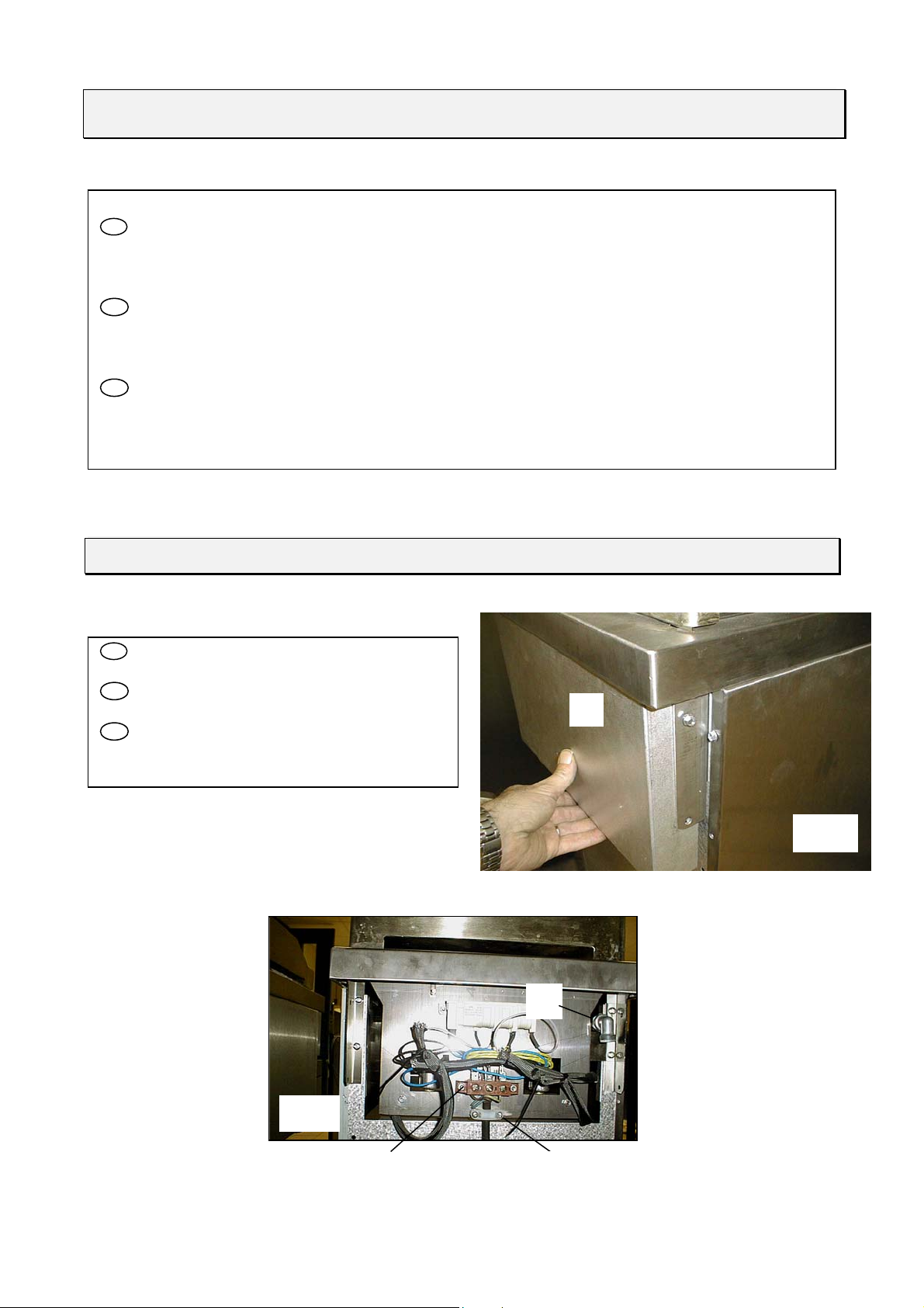
FR Déposer le capot arrière (fig.2)
Procéder au raccordement en utilisant un câble
souple normalisé, au bornier E (fig. 3).
Fixer le câble au moyen du serre câble F.
GB Remove rear cover (fig. 2).
Use a standard flexible cable to connect to
terminal block E (fig. 3).
Secure the cable by means of cable clamp F.
NL Verwijder het achterpaneel (fig.2).
Aansluiten met genormaliseerd snoer op
klemblok E (fig. 3).
Zet het snoer vast met een kabelklem F
CHANGEMENT DE GAZ / CHANGE OF GAS/
OVERSCHAKELEN OP ANDERE GASSOORT
FR - Fermer le robinet de barrage avant toute intervention.
GB - Close the mains gas tap before carrying out any work.
NL - Draai de afsluitkraan dicht voordat de volgende handelingen worden uitgevoerd.
IMPORTANT / BELANGRIJK
FR - En cas d’utilisation avec un gaz autre que celui du réglage initial, il est impératif de procéder à l’échange des
injecteurs et de reprendre les réglages comme définis ci-après.
GB - In case of use with a gas other than that for which the appliance was initially set up, it is crucial to replace the
injectors and modify the adjustments as defined below and.
NL - Als een ander gas gebruikt wordt dan dat waarvoor het apparaat oorspronkelijk was ingesteld, is het absoluut
noodzakelijk de injectors te verwisselen en het apparaat opnieuw in te stellen volgens onderstaande instrukties.
1 2
1234 56
A
B & B1
S1
X
LN
FR Spécial U.K :
L’appareil prévu pour être relier à un circuit en gaz naturel est équipé d’un régulateur de pression gaz permettant à
cet appareil de fonctionner sous une pression de 15 mbar.
Dans le cas d’un changement de gaz, il est nécessaire de retirer ce régulateur de pression et d’alimenter l’appareil en
gaz butane ou propane directement au point de raccordement de l’alimentation gaz de l’appareil.
Procéder, comme lors de tout changement de gaz, aux nouveaux réglages (injecteurs, air primaire, …). Voir annexe
technique 2.
GB Spécial U.K :
The oven is designed to run on natural gas and is therefore fitted with a pressure regulating valve that allows it to be
used at a pressure of 15 mbar.
If a different type of gas is to be used, this pressure regulating valve must be removed and the gas supply connected
directly to a source of butane or propane.
As always when changing the type of gas, the injectors, primary air, etc. must be adjusted. See technical appendix 0.
Date de mise à jour : 29/09/2009 - FT 98a - FR / GB / NL- Révision 04 Page 9 sur 15
FR Procéder au réglage de la bague d’air J (voir
fig. 11, tableau 9en annexe 2).
GB Loosen the screw that secures the air ring Jand
then adjust (see fig. 11, table 9 in appendix 2).
NL Verwijder de bodemplaat. Draai de borgschroef
van de luchtring Jlos en stel de luchtstroom in (zie
fig. 11, tabel 9, bijlage 2).
Réglage de l’air primaire / Adjustment of primary air / Instellen van primaire luchtstroom
BRULEUR / BURNER / BRANDER
Accès au brûleur : Déposez la plaque / To access burner : Remove plate Toegang tot de brander : Verwijder de plaat.
Fig. 11
J
FR Retirer la vis de fixation de la trappe (repère G fig.
7).
Dévisser le bûleur H (fig. 8).
Retirer la vis poiteau I (fig. 9)
Echanger le/les injecteurs J(fig. 10, tableau n° 8 en
annexe 2).
GB Retirer la vis de fixation de la trappe (repère G fig.
7).
Dévisser le bûleur H (fig. 8).
Retirer la vis poiteau I (fig. 9)
Echanger le/les injecteurs J(fig. 10, tableau n° 8 en
annexe 2).
NL Retirer la vis de fixation de la trappe (repère G fig.
7).
Dévisser le bûleur H (fig. 8).
Retirer la vis poiteau I (fig. 9)
Echanger le/les injecteurs J(fig. 10, tableau n° 8 en
annexe
2
).
Fig. 8
H
G
Fig.7
Fig. 9 I
Fig. 10
J
Date de mise à jour : 29/09/2009 - FT 98a - FR / GB / NL- Révision 04 Page 10 sur 15
Réglage des sécurités par thermocouple / Adjustment of thermocouple safety cut-outs
Instellen van de thermokoppelbeveiligingen
K
Fig. 12
FR Si le brûleur s’éteint, après avoir maintenu enfoncée à fond la
manette une vingtaine de secondes; vérifier : Le serrage
(modéré) de la tête magnétique sur le robinet, que la pointe du
thermocouple Lsoit bien léchée par la flamme (fig.13) et le
bon état de propreté des thermocouples et têtes magnétiques.
GB If the burner goes out, having kept the control knob pushed in
for roughly twenty seconds, check : (Moderate) tightening of
magnetic head on the valve, the thermocouple Ltip actually
touches the flame (Figure 13). and the thermocouples and
magnetic heads are clean.
NL Als de brander uitgaat nadat u de knop twintig sekonden lang
ingedrukt hebt gehouden moet gecontroleerd worden : Of de
magneetkop goed op de kraan is vastgedraaid (matig vast), of
de vlam goed aan de punt van het thermokoppel L lekt (fig.
13). en of thermokoppels en magneetkoppen volkomen schoon
zijn.
Réglage du débit réduit des brûleurs / Adjustment of reduced flowrate of burners / Instellen
van minimumstand branders
FR Après raccordement ou changement de gaz, il est impératif de reprendre ce réglage. Déposer la manette,
allumer le brûleur, passer en position min., puis agir à l’aide d’un tournevis sur la vis de réglage K (fig. 12).
Nota: les flammes sont réduites au ¼ de leur taille en position mini, le brûleur ne doit pas s’éteindre en passant
de la position maxi à la position mini.
GB After connection or change of gas, it is crucial to modify this adjustment. Remove the control knob, light the
burner, adjust to minimum setting, then use a screwdriver to set the adjusting screw K(fig. 12).
Note: flame is reduced to ¼ of its size in the minimum setting, the burner must remain lit when changing from
maximum setting to minimum setting.
NL Na het aansluiten of na het overschakelen op een andere gassoort, is het absoluut noodzakelijk de
minimumstand van elke brander opnieuw in te stellen. Verwijder de bedieningsknop, steek de brander aan, zet
hem op minimumstand en draai de stelschroef Kin de gewenste stand met behulp van een schroevedraaier (fig.
12).
N.B.: in minimumstand worden de vlammen teruggebracht tot een 1/4 van hun grootte. Bij het overgaan van
maximum- naar minimumstand mag de brander niet uitgaan.
L Fi
g
. 13