Amberg Technologies AG TSP 303 Plus User manual

TSP 303 Plus
See ahead - build safer
Operation manual
Version 3.1.0.0, 05/2018
© Amberg Technologies AG, 2012-2018
Art. No. 20820
Amberg Technologies AG
Trockenloostrasse 21
8105 Regensdorf
Switzerland
Phone: +41 44 870 92 22
Mail: [email protected]
http://www.amberg.ch/at


Operation manual
© Amberg Technologies AG, 2012-2018 Page 3 of 84
Table of Contents
Welcome to TSP 303 ................................................................................................................ 5
1 Conventions used in this manual ................................................................................... 5
2 Software licence agreement ........................................................................................... 6
3 Software installation ........................................................................................................ 6
3.1 System requirements ........................................................................................... 6
3.2 Software installation ............................................................................................. 7
4 Software licensing ........................................................................................................... 8
4.1 Hardkey version ................................................................................................... 8
4.2 Softkey version ..................................................................................................... 8
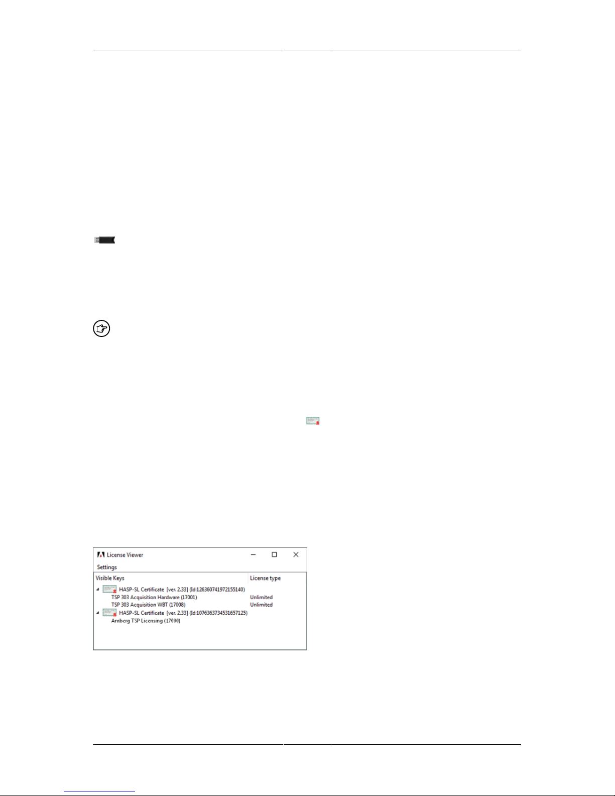
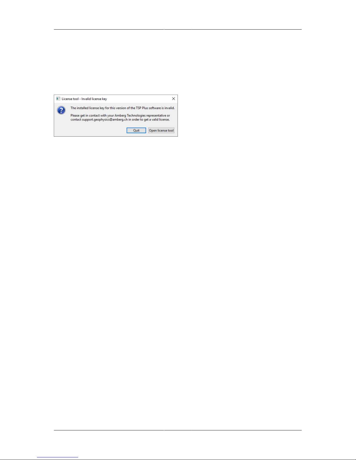
4.3 License tool .......................................................................................................... 8
4.4 License upgrade ................................................................................................... 9
5 Maintenance & Support contract .................................................................................... 10
1 Safety directions ...................................................................................................................... 11
1.1 Disclaimer of liability .................................................................................................... 11
1.2 Use of instrument ......................................................................................................... 11
1.2.1 Intended use of instrument ............................................................................... 11
1.2.2 Prohibited uses ................................................................................................. 11
1.2.3 Limits of Use ..................................................................................................... 11
1.2.4 Prohibited modifications .................................................................................... 12
1.2.5 Danger working within tunnel environment ...................................................... 12
1.2.6 Other dangers ................................................................................................... 12
2 TSP 303 Plus system components ........................................................................................ 13
3 Preparing a TSP measurement .............................................................................................. 17
3.1 General ......................................................................................................................... 17
3.2 Marking of the measurement layout ............................................................................ 17
3.3 Drilling and protecting bore holes ............................................................................... 18
3.4 Check list of required items ......................................................................................... 19
4 Performing a TSP measurement ............................................................................................ 21
4.1 Measuring of the layout geometry ............................................................................... 21
4.2 System setup ................................................................................................................ 25
4.2.1 Assembling receiver .......................................................................................... 26
4.2.2 Checking receiver bore holes ........................................................................... 28
4.2.3 Setting the receiver ........................................................................................... 30
4.2.4 Connecting Toughbook with Recording Unit .................................................... 36
4.2.5 Checking battery charge ................................................................................... 36
4.2.6 Use of external batteries .................................................................................. 37
4.2.7 Seismic noise test ............................................................................................. 37
4.2.8 Trigger/Shot test (Trigger mode Standard) ...................................................... 38
4.2.9 Charge configuration ......................................................................................... 38
4.2.10 Detonator preparation & system setup ........................................................... 39
4.2.11 Standard system setup with explosive source ............................................... 41
4.2.12 Wire Break system setup with explosive source ............................................ 43
4.2.13 Hammer system setup with impact hammer source ...................................... 48
4.3 Seismic data acquisition .............................................................................................. 49
4.3.1 Data acquisition procedures ............................................................................. 49
4.3.2 Amberg TSP Plus Workspace .......................................................................... 53
4.3.3 Amberg TSP Plus Menus & Tool bars ............................................................. 54
4.3.4 Starting data acquisition ................................................................................... 54
4.4 Acquisition wizard ........................................................................................................ 55
4.4.1 Data affecting settings ...................................................................................... 55

Operation manual Operation manual
Page 4 of 84 © Amberg Technologies AG, 2012-2018
4.4.2 Display settings ................................................................................................. 56
4.4.3 Wizard 1: Acquisition setup .............................................................................. 56
4.4.4 Single shot recording (source type: explosives ) ............................................. 57
4.4.5 Multiple shot recording (source type: explosives) ............................................ 63
4.4.6 Single shot recording (source type: hammer) .................................................. 65
4.5 Data recording .............................................................................................................. 70
4.5.1 Single shot recording mode .............................................................................. 70
4.5.2 Multiple shot recording mode ........................................................................... 72
4.6 Dismounting the receiver ............................................................................................. 74
5 System maintenance ............................................................................................................... 77
5.1 Charging Batteries ....................................................................................................... 77
5.2 Cleaning of system components ................................................................................. 77
5.3 System overhaul .......................................................................................................... 77
6 Disposal ................................................................................................................................... 79
6.1 Disposal of TSP components ...................................................................................... 79
6.2 Disposal of batteries and accumulators ...................................................................... 79
7 Declaration of Conformity ....................................................................................................... 81

Operation manual
© Amberg Technologies AG, 2012-2018 Page 5 of 84
Welcome to TSP 303
Congratulation on purchase of the TSP 303 system.
From the use of innovative technologies a more rapid construction of extremely complex un-
derground structures is possible. Examples might be the use of tunnel boring machines, with
advance rates of up to 20 m or more each day, or advanced drill and blast techniques. In both
cases, the safety and progress of the project is based on the assumed knowledge of the rock's
properties ahead of the face. It is possible to obtain additional information by drilling probe
holes but these are costly and considerably delay the tunnel heading.
The Tunnel Seismic Prediction - TSP®, a rapid, non-destructive and highly sophisticated mea-
suring system, is especially designed for underground construction works. The TSP® method
was first introduced to the underground construction market in 1994. Since then it has been
successfully used on more than 1'000 underground projects worldwide.
TSP 303 Plus is a ready to use system to measure seismic reflected waves and to evaluate
geology ahead the tunnel face in 3D. The goal is to predict unforeseen changes in rock condi-
tions which too often cause unnecessary costly downtime and problems.
This Method provides:
■A prediction of major changes in the rock structure both ahead of the tunnel face and around
the tunnel
■The evaluation of mechanical properties of the rock ahead of the face.
In most rock formations the TSP® method can provide data up to 150 m ahead of the face
and in hard rock even more than 200 m. The third system generation of TSP – the TSP 303
Plus with its Amberg TSP Plus software – builds on the experience and features of the already
proven TSP® 202 and TSP® 203PLUS systems. Amberg TSP Plus software can acquire,
process and evaluate data all within the common Microsoft Windows interface. It is capable
to characterize the rock mass through the calculation of rock mechanical parameters, such as
elastic Moduli and Poisson's ratio, along the entire area of investigation. With this information
it is possible to recommend suitable measures to reinforce weak rock zones for maximum
safety and optimum advance rates. Amberg Technologies AG has invested its considerable
knowledge and experience into the development of this system. We are sure you will enjoy
its high standard of accuracy, user friendliness and ease of handling and we wish you many
successful projects using this equipment and software.
Please read this manual carefully together with enclosed operating instructions of ac-
cessories before working with the equipment.
Please consider the safety references.
1 Conventions used in this manual
Since errors in the manual and in the program cannot possibly be prevented with absolute cer-
tainty, Amberg Technologies AG is always grateful for comments and feedback. The circum-
stances and location involved when an error occurred should be described as accurately as
possible.
Information to prevent injury to yourself when trying to complete a task.

Welcome to TSP 303 Operation manual
Page 6 of 84 © Amberg Technologies AG, 2012-2018
Information to prevent damage to the components when trying to complete a task.
Information that you must follow to complete a task.
Additional information.
Information using features efficiently.
2 Software licence agreement
You can find the software license agreement under the following link:
http://www.ambergtechnologies.ch/license-agreement
3 Software installation
This section describes the installation of the software and its components.
3.1 System requirements
The table below shows computer specifications necessary for the data processing
Table 1. System requirements
Operating system Windows 7 (64 bit), Windows 10 (64 bit)
RAM Minimum 8 GB RAM required
Hard disk capacity Fast hard disk with minimum 20 GB free space or external hard
disks with USB 3.0 preferably
Processor Multi core processor, minimum 2 GHz each recommended
Printer Any printer with Windows printer driver
For the data collection it is recommended to use the Panasonic Toughbook delivered with the
system. Other computers are not supported by Amberg Technologies. Do not run any other
software on the measuring computer as required. Switch off any firewall and other security
based software (virus scan, etc.). OS Windows XP and Windows Vista as well as Windows 7
32-bit are not being supported.
3.1.1 Graphic card driver troubleshooting
It may happen that on the system you have installed Amberg TSP Plus software, the 3D graph-
ical content is not displayed correctly or not shown at all. Mainly, the reasons are outdated
graphic card drivers. In such cases, updating graphic card drivers to the latest version is re-
quired. For necessary updates, please update the drivers of installed graphic card by most
recent servicepacks/drivers provided by the card manufacturer.
Graphic card drivers of Panasonic Toughbooks delivered with software version Amberg
TSP Plus 2.0.0.0 (or newer) by Amberg Technologies are up to date. Updates are not
necessary.

Operation manual Welcome to TSP 303
© Amberg Technologies AG, 2012-2018 Page 7 of 84
In case updates are necessary, read the graphic card manual before you download and
update drivers, carefully. Before proceeding with the installation, verify the driver you
downloaded supports your graphics card.
3.2 Software installation
3.2.1 Latest software release
You may download the latest software release of Amberg TSP Plus with personal login infor-
mation from the following website: www.ambergtechnologies.ch/downloads. If you don't have
a valid login access, please let us know and contact us at: <[email protected].>
3.2.2 Installation
The Amberg TSP Plus program is supplied as install executable in compressed form. The
program can only be used on the hard-disk after it has been installed.
The procedure is as follows:
1. Attach USB flash drive of Amberg Technologies.
2. A menu is automatically loaded and displayed. Select from here Amberg TSP Plus exe-
cutable.
3. If you have downloaded the program from the Internet, unzip the file to an empty directory
and double-click on the file AmbergTSPplus_(Version).exe.
4. Follow the instructions during the installation.
During the installation, the wizard will ask for TSP USB driver installation. When installing the
software for the very first time, it is necessary to select this option.
Do not plug the USB software dongle before the appropriate drivers have been installed
on your computer. Please note that for the dongle driver installation you need to have
local administration rights on your computer.
Please install and remove the dongle only when the computer is switched off. Other-
wise, the dongle can be damaged.
3.2.3 Software updates
Whenever there is a new release of the software Amberg TSP Plus, simply install it according
to the instructions above.
You are entitled to run the downloaded application version if the Maintenance & Support
contract of your dongle was valid at the release date. More information about the M&S contract
is available in: Section 5 Maintenance & Support contract.
3.2.4 Uninstallation
Please use the function "Uninstall Amberg TSP Plus" to remove the software from your oper-
ating system.
Please remember that only files which have not been modified since installation can be unin-
stalled. This means that data files can eventually not be uninstalled automatically. They need
the be deleted manually (e.g. with Explorer).

Welcome to TSP 303 Operation manual
Page 8 of 84 © Amberg Technologies AG, 2012-2018
4 Software licensing
For access to the full functionality of the TSP 303 data acquisition, two types of license keys
are supported, Hardkeys and Softkeys. Hardkeys are integrated in the Recording Unit, while
Softkeys are being embedded in the Windows registry of the delivered Toughbook PC. From
model year 2015 on, the TSP 303 Plus system is shipped with Softkeys on your Toughbook
PC with regard to Data Acquisition.
4.1 Hardkey version
The TSP 303 Recording Unit is supplied with a Hardkey. The serial number can be seen un-
der Help > About Amberg TSP Plus or under Help > License tool... This only works, if the
Recording Unit is connected with the Toughbook PC. The connected Hardkey is indicated by
.
4.1.1 Installation of Hardkey drivers
Disconnect Toughbook from Recording Unit. Switch on the Toughbook PC. Install the Amberg
TSP Plus installation executable. Dongle drivers are installed together with the application.
The installation of any application only works with administrator rights. Please install
the application only, when the Toughbook is offline from the Recording Unit. Otherwise,
the Hardkey can be damaged.
4.2 Softkey version
The application Amberg TSP Plus is supplied with Softkey Certificates. The Certificates number
can be seen under License tool...Help > About Amberg TSP Plus or under Help > License
tool... Registered certificates are indicated by .
4.2.1 Installation of Softkey drivers
Disconnect Toughbook from Recording Unit. Switch on the Toughbook PC. Install the Amberg
TSP Plus application. Softkey drivers are installed together with the application.
4.3 License tool
To view and upgrade the licenses on the Hardkey/Softkey the separate license tool can be
used. To start the license tool, select Help > License tool... .
4.3.1 License viewer
The license viewer displays a list of all Hardkeys/Softkeys which are available on the present
device and the features licensed on these keys. To see the licensed features of a Hardkey/Soft-
key, expand its feature entries by clicking on the small triangle next to the visible key name.

Operation manual Welcome to TSP 303
© Amberg Technologies AG, 2012-2018 Page 9 of 84
4.4 License upgrade
A license upgrade is possible at any time, e.g. for having access to additional hardware and
acquisition features. The license upgrade progress is equal for Hardkeys and Softkeys
Upgrades will only be provided after purchase of license extensions or new licenses.
4.4.1 Creating a c2v file
Client-to-vendor (.c2v) files are used to transfer information of a Hardkey/Softkey from the
software user to the software vendor. Amberg Technologies may ask you for sending this file
to be able to upgrade your Hardkey/Softkey with new licensed features or extend the licensing
period of already licensed features.
To create a c2v file, right-click on the entry of the Hardkey/Softkey for which the c2v
file should be created. From the context menu select Create c2v file and specify the
location where it should be stored. Send the created Client to vendor files (.c2v) to
4.4.2 Updating from a v2c file
Vendor-to-client files (.v2c) are used to update a Hardkey/Softkey on the software user client
with new licenses, extend license periods or update licensed features. Amberg Technologies
will send you such a file in the process after purchasing license extensions or new licenses.
To update a Hardkey/Softkey from a v2c file, right-click on the entry of the Hardkey/Softkey
that should be updated. From the context menu select Update from v2c file and select the file
from its storage location. After updating a Hardkey/Softkey you may use the Refresh key data
function in the context menu to display the updated license information.

Welcome to TSP 303 Operation manual
Page 10 of 84 © Amberg Technologies AG, 2012-2018
5 Maintenance & Support contract
Whenever Amberg TSP Plus 2.0 is launched on your computer, the licence tool will
check the available dongles for licensed modules and options. Additionally, it checks the
Maintenance&Support contract flag (M&S) on your dongle to ensure that the dongle is autho-
rized to run the installed release of Amberg TSP Plus. The dongle will work only with releases
published within the M&S contract period.
The Amberg TSP Plus software is continuously improved and maintained. For updating to a
newer release of the application after the M&S contract period has expired, it is required to
renew it.
For doing this, please don't hesitate to contact your local distributor or Amberg Technologies
AG <[email protected]>.

Operation manual
© Amberg Technologies AG, 2012-2018 Page 11 of 84
Chapter 1 Safety directions
The TSP system concept is designed for performing seismic measurements in tunnels. There
are inherent dangers in working in this environment. There are also some safety measures
regarding the TSP system. It is essential to read these safety instructions carefully.
It is essential to consider the local tunnel safety regulations as well as the safety regu-
lations in this manual!
The following directions should enable the person responsible for the TSP system and the
operator to anticipate and avoid operational hazards. The person responsible for the instrument
must ensure that all users understand and obey theses directions. Read this manual and the
manuals of accessories carefully before you activate the instrument.
1.1 Disclaimer of liability
It shall be noticed, that the TSP system on the whole and each single component of the TSP
system holds no intrinsic safety for use in potentially explosive atmospheres. It means that all
TSP devices are not tested and consequently certified according to ATEX CE compliance or
other relevant directives on the incapability of igniting flammable gases or fuels, e.g. Methane,
by releasing sufficient electrical, electrostatic, electromagnetic or thermal energy. Any liability
for direct or indirect loss or damage (notably but not exclusively loss of profits and claims by third
parties) which may arise as a result of the non-fulfilment of AT's contractual obligations and/or
as a result of the operation, and/or the operational breakdown of any TSP system component
supplied by AT is hereby expressly excluded. In no event shall AT be liable for incidental or
consequential damages, even if AT shall have been given notice of the possibility of such
damages being claimed.
1.2 Use of instrument
1.2.1 Intended use of instrument
The TSP system is designed and suitable for the following applications, within the limits of its
intended conditions of use:
■Measurement of seismic waves generated by explosives in the rock mass around a tunnel.
■Recording and digital storage of the seismic wave signals on a control computer.
1.2.2 Prohibited uses
■Use of the instrument without instruction.
■Use others than the recommended applications for which the instrument is intended.
1.2.3 Limits of Use
Environment:
Suitable for use in an atmosphere appropriate for permanent human habitation: not suitable
for use in aggressive or explosive environments.
Local authorities and safety experts must be contacted before working in explosive
areas, close proximity to electrical installations or any similar hazardous situations.

Safety directions Operation manual
Page 12 of 84 © Amberg Technologies AG, 2012-2018
1.2.4 Prohibited modifications
All changes, modifications or conversions of the product are prohibited in order to fully
comply with the law. Changes could void the user's authority to operate the equipment.
1.2.5 Danger working within tunnel environment
It is essential to consider the necessary safety regulations of the security administration
and take all appropriate measures. Dangerous situations can arise through work in
tunnels, for example:
■Moving construction site vehicles
■Items thrown up or fallen down by passing vehicles.
■Electric current flow through lines.
■Oxygen deficiency.
The above is not a complete list of dangers. The TSP system should only be used by persons
who are authorised by the responsible person and when all safety precautions are being ob-
served. The manufacturer/supplier does not take any responsibility for the safe operation of
the equipment.
1.2.6 Other dangers
The TSP system contains parts and devices which are operated by the user. With intended
use the following references must be considered:
■During drilling bore holes and installation of the receiver, avoid placing any part of
the body (e.g. fingers) between working tools (e.g. bore hammer, bore jumbo, etc.)
and installation tools.
■Single boxes of the TSP system can weigh up to 12 kg. However, incorrect lifting
technique can cause back pain or associated problems. Consider the maximum lifting
limits and get help if required.
■The TSP system is supplied with rechargeable batteries. Inappropriate use of the
battery may lead to an explosion. Consider the warnings and manuals for the correct
handling of the batteries. Only use batteries according to specifications of Amberg
Technologies.

Operation manual
© Amberg Technologies AG, 2012-2018 Page 13 of 84
Chapter 2 TSP 303 Plus system
components
The TSP 303 Plus system configuration consists of the items as shown in the figure below. For
a more detailed specification of each component please refer to the TSP 303 Plus Data sheet.
Figure 1. TSP 303 Plus system package
1 case Recording Unit
2 cases Receiver Units
1 case Accessories
2 bags Receiver protection tubes & installation tubes
4 packages, each two with TSPdowel and SeisBond® cartridges

TSP 303 Plus system components Operation manual
Page 14 of 84 © Amberg Technologies AG, 2012-2018
Figure 2. TSP 303 Plus system components at a glance
Recording Unit
Panasonic Toughbook with data upload cable
Receiver Unit case containing:
2x 20 m Receiver cables on drum
Jaw wrench
Cable drum holder
Installation tool
2 Receivers
Knitting-latex gloves
Accessories case containing:
3 m Folding meter
10 m Trigger cable on drum
50 m Shooting cable on drum with removable cable drum holder

Operation manual TSP 303 Plus system components
© Amberg Technologies AG, 2012-2018 Page 15 of 84
Multi tool
LED Lenser torch
Laser DistoMeter
Electronic level
Charger for Panasonic Toughbook
Charger for Li-Ion battery of Recording Unit
Multifunctional Trigger Box
2 Installation tubes
4 Protection tubes
Telescopic tamping rod for SeisBond® cartridges
cartridge charger (attached to tamping rod)
SeisBond® cartridges
TSPdowels
Due to export regulations and restrictions the blasting machine is not part of the TSP
system and must be purchased or provided by the client. Furthermore, all explosives
and detonators have to be provided by the client or customer with strict regard to rele-
vant local safety regulations.

Page 16 of 84

Operation manual
© Amberg Technologies AG, 2012-2018 Page 17 of 84
Chapter 3 Preparing a TSP
measurement
3.1 General
The sketch below shows a typical TSP seismic layout. Usually, data acquisition can be carried
out with a single shot line arranged on either side of the tunnel. As shown below, the shot line
is on the left side looking towards the face since possible fault planes are anticipated to strike
the tunnel from the left side first. In order to obtain more data, which might become necessary
in complex geologic conditions, it is useful having a second shot line on the opposite side.
However, using only one shot line and four receiver units is more economical. Even when the
geology is not known in terms of preferred strike directions, the positioning of receiver units on
both sides of the tunnel will provide a sufficient 3D-image in normal geology.
Figure 3. Specifications of TSP measurement layout
3.2 Marking of the measurement layout
Having decided the investigation layout according to the anticipated strike direction the posi-
tions of the receiver and shot holes have to be defined. Apart from special cases the standard
layout should be used and the following procedure is recommended:
1. Determine the chainage (Tunnelmeter) of the tunnel face at time of TSP measurement.
2. Define the shot hole position that is closest to the tunnel face (S24). Depending upon the
accessibility at the side wall in front of the tunnel, the closest shot hole should be one to five
meters from the tunnel face or as close as possible to the face in case of TBM operation.
3. Based on the shot hole closest to the face (S24), define the remaining 23 shot hole positions
(S23...S1) at the same level with a 1.5 m spacing.
4. Move further 15 m from shot hole position S1 and define the front receiver hole position (e.g.
RCV FL) at the same level.
5. Move further 5 m from front receiver hole position (e.g. RCV FL) and define rear receiver
hole position at the same level (e.g. RCV RL).
6. Define the remaining two receiver hole positions on opposite tunnel side walls at same level
(e.g. RCV FR and RCV RR).

Preparing a TSP measurement Operation manual
Page 18 of 84 © Amberg Technologies AG, 2012-2018
The shot hole interval should be 1.5 m. For imperative reasons, e.g. due to lack of space
or obstacles at the side wall, a variant shot hole spacing may become an option. In any
case, single intervals should be in the range of 1.2 to 2 m. In case of insufficient space
for the required total shot-receiver hole layout, make sure that the required number of
24 shot holes is held by defining smaller shot hole spacings respectively. If the option
of shorter intervals is impossible, ensure at least a minimum number of 18 shot holes.
The alignment of receiver and shot bore holes should comply with the specifications given in
the following table.
Shot bore hole (S)
Number: 24, all along one tunnel wall side
Diameter: 38 - 45 mm
Depth: 1.5 m in solid rock
Horizontal angle: perpendicular to the tunnel axis
Vertical angle: 15-20° downwards from horizontal (because of water tamping
of explosive charges)
Height: 1.20 - 1.60 m from invert (all same level)
Position: Starting at 1 - 5 m from the tunnel face or as close as possible
to the face in case of TBM operation; 1.50 m spacing
Receiver bore hole (RCV)
Number: 4, two each on opposite tunnel sides
Diameter: 50 mm
Depth: 2.00 - 2.05 m
Horizontal angle: perpendicular to the tunnel axis
Vertical angle: 5-10° upwards from horizontal
Height: 1.20 - 1.60 m from invert (all same level)
Position front RCV: 15 m from face most far shot hole: one each on opposite side
walls
Position rear RCV: 5 m from front receivers: one each on opposite side walls
When using an impact hammer source, the drilling of the shot holes can be dispensed.
However, the receiver and shot point alignment is both same for explosives and hammer
source.
3.3 Drilling and protecting bore holes
Drilling shot holes in unstable rock mass formation may cause a collapse of the holes after a
certain time. To prevent this, a thin-walled plastic pipe (external diameter approx. 30 mm, length
approx. 1.5 m) can be used to temporarily support the hole. The shot charges can be pushed
through the pipe whilst slowly removing it. This should be carried out just before shooting. The
pipes may be used again for the next TSP measurement. If the rock formation is very unstable,
however, and the protecting pipe cannot be removed, it is possible to shoot through the pipe.
Protect the shot holes with thin-walled plastic pipes to temporarily support the hole in
unstable rock formation.

Operation manual Preparing a TSP measurement
© Amberg Technologies AG, 2012-2018 Page 19 of 84
3.4 Check list of required items
Blasting Machine Electrical HI-blasting machine, Voltage outlet of 1000V - 1500V,
Capacity 40 µF - 80 µF
Explosives 30 pcs. of detonating cord (PETN) or gelatinous w/ detonation
velocity > 6000 m/s, 50-150 g /piece
Detonators Electric: 30 pcs., highly insensitive, delay interval: 0 (instanta-
neous), or
Non-electric: 30 pcs, any delay interval, or
Electronic: 30 pcs
Wire break cable Single wire covered cable (preferably cooper), with an internal
diameter of ~0.6 mm (AWG 22) or a section of ~0.3 mm2.
Thin plastic tubes
(PVC etc.)
For shot holes to prevent drill hole collapse (optional)
Water supply Water hose for tamping of the shot charges
Compressed air Useful to remove water or pebbles from bore hole
Cushion of geo-tex-
tiles
May prevent damage from blow-out (1 x 1 m) (optional)
Marking spray, red Starting at 1 - 5 m from the tunnel face or as close as possible
to the face in case of TBM operation; 1.50 m spacing
Tape measure Preferably 50 m length
Normal lights Possibly 1 or 2 spotlights
The wire break cable is needed in case that: 1) blasting machine is not available, 2)
nonel or electronic detonators will be used or 3) detonators with delay will be used.

Page 20 of 84
Table of contents
Other Amberg Technologies AG Measuring Instrument manuals