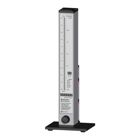
IBR C100-AE User manual

M e t r o l o g y
Document No. : D2F202 001
Edition : September 2004
Copyright : IBR
Messtechnik GmbH & Co. KG
INSTRUCTION MANUAL
C100-AE
Column gauge
Incl. pneumatic converter

2
Instruction Manual C100-AE
Contents
1. Introduction
1.1 General information .............................................................................................................. : 3
1.2 Measurement and display features ...................................................................................... : 3
1.3 Front and rear panel ............................................................................................................. : 4
1.4 Dimensions .......................................................................................................................... : 5
1.5 Connectors round-up ........................................................................................................... : 5
1.6 Technical data....................................................................................................................... : 6
2. Getting started
2.1 Delivered items...................................................................................................................... : 7
2.2 Fitting the footplate................................................................................................................ : 7
2.3 Mounting the air filter and pressure regulator ...................................................................... : 7
2.4 Pressure connection ............................................................................................................. : 8
2.5 Connecting gauge heads .....................................................................................................: 8
2.6 Connecting a foot or hand switch.......................................................................................... : 9
2.7 Connecting an adapter for tolerance outputs ....................................................................... : 9
2.8 Connecting a PC, multiplexer or statistic printer ................................................................... : 10
2.9 Connecting to the power supply ........................................................................................... : 10
2.10 Power on / Self test ............................................................................................................... : 10
3. Programming the column gauge
3.1 Key functions......................................................................................................................... : 11
3.2 Foot switch functions............................................................................................................. : 11
3.3 Quick programming guide for programmers in a hurry ........................................................ : 12
3.4 Programming menu .............................................................................................................. : 13
3.5 Basic settings / Setup menu.................................................................................................. : 16
3.6 Restoring factory settings...................................................................................................... : 20
3.7 Changing system settings .................................................................................................... : 20
3.8 Error messages / Error corrections ...................................................................................... : 20
4. Working with the column gauge
4.1 First start-up ......................................................................................................................... : 22
4.2 Measurement operation ...................................................................................................... : 22
4.3 Restrictor adjustment ........................................................................................................... : 22
4.4 Automatic gauge calibration ................................................................................................. : 24
4.5 Working in Dynamic measuring mode ................................................................................. : 24
5. Maintenance and care .................................................................................................................. : 25
6. Supervision of the pressure supply ........................................................................................... : 25
7. RS232 interface
7.1 Transmission format ............................................................................................................. : 25
7.2 Data format ........................................................................................................................... : 25
7.3 Requesting measured values ............................................................................................... : 26
7.4 Transmission of measured values ........................................................................................ : 27
7.5 Importing measurement values into Windows applications ................................................. : 27
7.6 Importing measurement values into MS-EXCEL ................................................................ : 28
8. Pin assignments of connectors
8.1 Connectors of the column gauge ......................................................................................... : 29
8.2 Plug-in terminal blocks ......................................................................................................... : 29
9. Accessories and order information............................................................................................. : 31
10. Safety Instructions ........................................................................................................................ : 32
11. Declaration of conformity ............................................................................................................ : 33
12. Guarantee ....................................................................................................................................... : 33

3
Instruction Manual C100-AE
1. Introduction
1.1 General information
1.2 Measurement and display features
STANDARD MEASURING MODE :Displays the current measured value
DYNAMIC MEASURING MODE : MINIMUM
MAXIMUM
TIR = ( MAX - MIN )
MEAN = ( MAX + MIN )
2
Units
mm and INCH selectable
Measuring range / Resolution
± 1,5 mm / 0.1 µm, 0,059 / 0.00001 inch
± 15 mm / 1 µm, 0,59 / 0.0001 inch
Numeric display ranges
Relative measurements ± 9.9999 mm / ±99.999 mm, ±.99999 inch / ±9.9999 inch
Absolute measurements 0...99.9999 mm / 0...999.999 mm, 0...9.99999 inch / 0...99.9999 inch
The column display C100-AE is an electronic gauge
with integrated pneumatic measurement converter.
The compact design of the microprocessor-based
electronics and pneumatic measurement convert
allows static and dynamic measurements of work-
pieces in an industrial environment.
Highly sophisticated measurement programmes
simplify measuring and gauge calibration.
The numeric display is designed for output of
absolute or comparative measurement values and
classification of the machined work pieces. The three-
coloured column display features programmable
tolerance points and supports an accurate assessment
of the processing quality. The C100-AE is an ideal
tool for manual examination of measurement values or
automatic gauging applications with computers or PLC
units.

4
Instruction Manual C100-AE
Numeric display
Mode / Units
Programming Menu
Keypad
Column display ranges
± 1,5000 mm ± 0,15000" The column display features 3 colours ( red, green, yellow ) with
±0,5000 mm ± 0,05000" automatic colour selection corresponding to the given
± 0,1500 mm ± 0,01500" tolerance limits.
± 0,0500 mm ± 0,00500" It is possible to programme up to 4 tolerance limits.
± 0,0150 mm ± 0,00150" Tolerance limits are marked on the column display.
± 0,0050 mm ± 0,00050"
Notice:
The measurement range of the column display can be set in the Setup menu to a fixed value or to AUTO
mode. In AUTO mode the column gauge automatically selects the smallest possible range on the base of
the programmed tolerances. The selected range is displayed in the upper right corner of the front panel.
1.3 Front and rear panel
Column display range
and unit
3 coloured LED column
RS232 male connecto
r
Tol. Out socket
Power switch
Mains inlet
Tolerance marks
( max.4 )
For future expansion
Connectors sketch
Integrated pneumatic
converter
Connector for gauge
heads
Restrictor for air flow
ad
j
ustment
Pressure input
2 - 3 bar
(
30 - 45
p
si
)
Type label
Type label

5
Instruction Manual C100-AE
102 mm
136.5 mm
390 mm
370 mm
45 mm
52mm
5°
1.4 Dimensions
1.5 Connectors round-up ( all accessories shown )
Figure :
Column display on footplate

6
Instruction Manual C100-AE
1.6 Technical data
Mechanical characteristics
Case Aluminium, epoxy powder coated
Front panel Acrylic-glass front panel, anti-reflex
Keypad Spring loaded keys for feedback with sturdy rectangular
caps
Dimensions W x H x D / Weight 45 x 370 x 52 mm / approx. 820 g
Electrical characteristics
Power block Primary switched power supply with wide voltage input
Main voltage / Frequency 85 ... 260 V AC / 47...440 Hz
Max. power consumption 5,5 VA
Displays
Column display Scale with 100 LED's, 3-coloured, 254 mm long, automatic
colour selection and programmable tolerance marks
Numeric display 6-digit LED display; 6,4 mm, red
Mode, Unit, Range, Programming light fields 16 light fields with changeable labelling
Connections
Air pressure supply connection
Quick coupling for PU hose 8/6 mm
Air pressure supply ( input pressure regulator ) 4 - 8 bar / 60 - 120 psi
Air pressure ( C100-AE input ) 2 - 3 bar / 30 - 45 psi ( filtered air < 5µm )
Outlet of measuring air Coupling DN2,7
Connection of gauge head Nipple DN2,7 for PU hose 6/4 mm
Interface ( RS232 ) 9-pin. SUB-D male connector, Hardware according to EIA
RS232 Standard, Data format according to OPTO RS232
Trigger input / Tolerance outputs ( Tol. Out ) 9-pin. SUB-D socket
Trigger input for ext. contact / foot switch and serial output
for OC3, OE3 and OP3 adapters
Measurement parameters
Measurement range / Resolution ± 1,5 mm/ 0,1µm or ± 15 mm / 1µm
± 0,059 / 0.00001 inch or ± 0,59 / 0.0001 inch
Measurement rate 31,25 measurements / sec.
Resolution 16 Bit ( internal )
Environmental conditions
Operating temperature range 0 ... 45°C
Storage temperature range -30 ... +60°C
Type of protection IP50 ( CEI / IEC 529 )
Electromagnetic compatibility ( EMC )
Electromagnetic compatibility ( EMC ) Generation of interference according to EN50081-2
Resistance to interference according to EN50082-2

7
Instruction Manual C100-AE
2. Getting started
2.1 Delivered items
The column gauge is delivered with a power cable, a footplate ( with 2 screws M3x6 ), nipple for gauge
heads ( for PU - hose 6/4 mm ), an air filter/pressure regulator with nipple of pressure connector for
9mm hose, wall bracket with nut, PU - hose 8/6mm ( 2m ), instruction manual and programming card.
Further accessories, e.g. foot switches, adapters, etc. as listed in the delivery note.
Please, check the delivery for completeness and save the packaging for future use.
2.2 Fitting the footplate
Fix the footplate to the instrument and place on a sturdy
and level surface.
2.3 Mounting the air filter and pressure regulator
To mount the filter and the pressure regulator a mounting kit is supplied together with the C100-AE.
The kit consists of a wall bracket and a nut to fasten the filter / regulator to the bracket.
Attention : For keeping condense water away from the C100-AE measuring converter the
air filter and pressure regulator should be mounted below the C100-AE.
Maintance : Open the screw below the air filter each day to remove the water
Bracket

8
Instruction Manual C100-AE
2.4 Pressure connection
The connection between the mounted pressure regulator and the pressure input of the C100-AE is done by
the delivered PU hose 8/6 mm ( 2 m ). The hose is pushed on both sides of the connectors and is secured
by a nut.
!!! Tighten nuts only by hand.
Watch that no dirt is in the connection hose. If necessary blow trough the connection hose before
mounting.
Connect the pressure ( 4 – 8 bar ) by the coupling DN7,2 to the pressure regulator. Adjust the pressure
regulator to 2 - 3 bar ( 30 - 45 psi ).
2.5 Connecting gauge heads
In order to connect the pneumatic gauge head the C100-AE is delivered inclusive a DN2,7 nipple
suitable for a PU hose 6/4 mm.
The PU hoses of the measuring head is pressed onto the nipple and fastened with a nut.
!!! Tighten the nut only by hand.
Fit the gauge head with PU hose and DN2,7 nipple and connect them to the C100-AE converter.
To save compressed air the gauge head should be parked in a bore ( for example in a rejected part ). !!!
Connect air pressure supply by mounting the coupling DN7,2 and adjust the pressure regulator at
2 - 3 bar / 30 - 45 psi.

9
Instruction Manual C100-AE
2.6 Connecting a foot or hand switch
Foot and hand switches can be connected to both the RS232 male connector and the Tol.-Out socket, to
be found at the rear of the column gauge. Please, use only the foot and hand switches supplied with the
instrument. When a foot or hand switch with an adapter-connector is used, it is possible to connect an
additional cable or an adapter to the RS232 or to the Tol.-Out connectors.
The functions of the foot switch can be set in the Setup menu and is identical for both connectors
RS232 and Tol.-Out.
Foot and hand switch types Art. No.
Foot switch IP32..................................... F602 001
Foot switch IP65 .................................... F602 002
Foot switch with adapter connector IP32 F602 003
Foot switch with adapter connector IP65 F602 004
Hand switch IP65 ................................... F602 010
Hand switch with adapter connector IP65 F602 011
Caution !!!
Fix the screws on all connections.
For pin assignment of connectors refer to chapter 6.
2.7 Connecting an adapter for tolerance outputs
Adapters for switching outputs of tolerances are connected
on the rear to the "Tol.-Out" Sub-D-socket.
A total of 5 switching outputs are available :
1. Above max. tolerance ( red )
2. Above max. tolerance ( yellow )
3. Measured value within range ( green )
4. Below min. tolerance ( yellow )
5. Below min. tolerance ( red )
Adapters for tolerance outputs : Art.-No.
Open collector-adapter OC3 ............ F603 001
Open emitter-adapter OE3 ............... F603 002
Opto coupler-adapter OP3 ............... F603 003
For pin assignment of adapters OC3/OE3/OP3 refer to annex 6,
For further information about the adapters see the technical specifications Document numbers
D2F603 001, D2F603 002, D2F603 003.

10
Instruction Manual C100-AE
USB
(Addresses 1...127)
RS232
(Opto RS232 format)
Mitutoyo Digimatic
Analogue output of
measurement value (± 10V)
2.8 Connecting a PC, multiplexer or statistic printer
To connect a PC ( COM 1 ...4), a multiplexer or
statistic printer use the "RS232" Sub-D
connector at the rear of the column gauge.
For pin assignment see chapter 6
Choose one of the following connecting
cables or adapters for connecting to a PC,
multiplexer, statistic printer or chart recor-
der.
PC-RS232 cable for connection to RS232 with adapter 9/25 pin ( COM1…COM4 ) ....................... F601 002
PC-USB cable for connection to PC USB incl. driver software to emulate COM1 - 127 ............. F601 020
RSD for connection to Mitutoyo Digimatic inputs ......................................................... F601 030
( cable converts OPTO RS232 to DIGIMATIC output )
RSA adapter for analogue output voltage with plug-in terminal block .......................... F601 031
( adapter converts OPTO RS232
→
± 10V analogue output )
2.9 Connecting to the power supply
First make sure that the rated voltage complies with the
electrical requirements indicated on the labels at the
rear of the instrument. If they do, connect the power cable
to the rear of the column.
Caution !!! The column must be connected to the power
supply only via a properly grounded safety socket.
2.10 Power on / Self test
Every time the column gauge is switched on the numeric display shows the different software versions
( AL -Assembling routines, HL - High-level routines ). A self test then runs automatically in order to check
all system components.
If an error is detected during a test routine, an error message appears on the numeric display. The self test
takes approximately 15 seconds.
During self test all displays are activated one after the other so that the user can check the display.
During the self test the RS232 interface of the column gauge remains inactive.

11
Instruction Manual C100-AE
3. Programming the column gauge
All programming and settings of the column gauge are done with the 4 keys on the front panel. The user is
taken step by step through the different menus with the help of the lamps and the numeric display. The
programming follows a logic structure and becomes self-explanatory after a short study.
3.1 Key functions
PRG/CAL When this key is pressed the gauge changes from Measuring to Programming mode or
viceversa.
ENTER On Measuring mode this key starts or finishes a dynamic measurement.
In Programming mode this key confirms the programmed values and selections.
ÏWhen this key is pressed in Measuring mode the measured value on the numeric display
is increased. A short pressure increments by 1. If the key is held down the measured value
is increased rapidly ( manual zero adjustment ).
In Programming mode the key is used to increase a given value or switch to the next
menu or function.
ÐWhen this key is pressed in Measuring mode the measured value on the numeric display
is reduced. A short pressure decrements by 1. If the key is held down the measured value
is rapidly reduced ( manual zero adjustment ).
In Programming mode the key is used to reduce a given value or to switch to the next
menu or function.
Ï& ÐWhen the Ïand Ð- keys are pressed simultaneously in Measuring mode either an
automatic zero adjustment or a gauge calibration is done.
If the Ïand Ðkeys are pressed simultaneously for more than 3 seconds the internal zero
adjustment offset and calibration value are erased. The numeric display shows the
uncalibrated pressure signal.
3.2 Foot switch functions
1. Start / Stop dynamic measurements
2. Output of measured value at RS232 output
3. Display control : trAnS →transfer of measured value to the display
hold →hold display value
4 Automatic zero adjustment or gauge calibration.
Notice : The functions 2 ... 4 can be switched on and off in the Setup menu.

12
Instruction Manual C100-AE
3.3 Quick programming guide for programmers in a hurry
Menu selection and programming
1. Use the PRG/CAL key to toggle from Measuring mode to Programming mode and viceversa.
2. In Programming mode the adjustable element is flashing.
3. The flashing element can be modified with the Ïor Ðkeys.
( Ïor Ð→+1, -1 or move to the next display field ).
4. Press the ENTER key to confirm a flashing setting.
Menu-Overview
Input of .... Numeric Display Input or selection...
Static measurement
Dyn. measurement ( MIN, MAX, TIR, MEAN )
mm
inch
Master value for zero adjustment
Master values for gauge calibration
Programming the column display
Zero point of column display
Tolerance limits 1...4 as deviation from
nominal value
Coefficients for pneumatic converter
Instrument parameters for operation ( see below )
a. Resolution ( 1µm / 0.1µm or 0.0001 inch / 0.00001 inch )
b. Column range ( Auto, ± 1,5mm to ± 50µm or 0.1500 inch ... 0.0005 inch )
c. Controlling of display output by foot switch ( oFF, trAnS, hold )
d. Automatic zero adjustment (using keypad on / oFF, using foot switch on / oFF )
e. Serial data transfer continuous - SoC on / oFF / foot switch - Sot on/ oFF
f. Automatic gauge calibration ( on / oFF )
g. Column display mode ( StAndA - from bottom, CentrE - from center, toP - from top )
h. Tolerance marks FLASH - Tolerance marks are flashing when measured value is out
of tolerance
i. Password to secure programming ( 6-digit number )
j. Filter time value ( oFF, 1 = 10msec, ... 6 = 1sec. )
For quick help during programming use the programming reference card !!!
The card will provide you with more information and should be your main aid.
First-time users of the column gauge should carefully read through the instructions given in the
following chapter, which deals extensively with the different programme steps.
Users with a basic knowledge should use the following chapter for reference.
Set.OP
Unit
Preset
Set.Pnt
Set.tol.
0.50 A
SetUP
Measuring mode Î
Unit Î
Master value
(
s
)
Î
Nominal valu
e
Î
Tolerances Î
Probe mixin
g
Î
Setu
p
Î

13
Instruction Manual C100-AE
3.4 Programming menu
Press the PRG/CAL key to switch from Measurement to Programming mode.
'SEt OP.' flashes on the numeric display.
The programming of the column gauge starts with the selection of the measuring mode.
Standard-Measuring mode ( static measurements )
Dyn. Measuring mode ( dynamic measurements )
Press the ENTER key to confirm 'SEt OP.'. The lamp DYN. Mode ( for measuring mode ) lights up and on
or oFF flashes on the numeric display.
Use the Ïand Ðkeys to enable ( on ) or disable ( oFF ) the Dynamic mode and confirm your choice with
ENTER key. If the Dynamic measuring mode is chosen, 'diSP' will appear on the numeric display and one
of the display options will be flashing at the same time.
MINIMUM
MAXIMUM
TIR = MAX - MIN
MEAN = ( MAX + MIN )/2
Use the Ïand Ðkeys to select the option and confirm your choice with the ENTER key.
'SEt OP' restarts flashing. Press the Ðkey to advance to the next menu and select the unit.
After pressing the ENTER key ( confirm flashing "Unit" ) in the 2nd menu you can select either „mm“ or
„INCH" by pressing the Ïor Ðkey. Confirm with the ENTER key.
Press the Ðkey to advance to the next menu.
Notice : a) If you change the unit, numeric values introduced in the programme, eg. master values,
nominal size values and tolerances do not change automatically.
b) Further units on request.

14
Instruction Manual C100-AE
The programming of a master value is base of the Automatic Zero Adjustment.
On Automatic zero adjustment ( do this by placing the master piece into the measuring fixture and press
the
Ï
and
Ð
keys simultaneously during Measuring mode ) the master value will be taken as the measured
value and appears on the numeric display.
When measuring comparative values ( shows the deviation to the nominal size on numeric and column
displays ) zero is programmed as master value.
When pneumatic converters are used, Automatic Gauge Calibration can be considered as an option. If this
option is chosen in the Setup menu "AutoCA" you will be prompted to program a second master value.
If you then enter the same value for both masters, the error message 'Err. 11' will appear. If you enter a
difference between the two masters with more than 3 mm the error message 'Err 12' will appear.
Notice : On Auto Zero Adjustment the zero position of the column gauge related to the master is
automatically adjusted by an offset value.
On Automatic gauge calibration the offset value ( zero point ) and the gain ( pneumatic
spread ) is calculated automatically by the column gauge.
The nominal value indicates the value to be chosen as zero point of the column display. If the nominal
value is 20 mm ( SEt.Pnt. is set to 20 mm ) the column display will show a deviation of 0,1 mm for a work
piece measuring of 20,1 mm.
Notice : The nominal value is used only for the zero position of the column display and does not
influence the numeric display.

15
Instruction Manual C100-AE
In this menu you can set a maximum of 4 tolerance points representing relative deviation from the
nominal value.
Programming starts by selecting one of the four tolerance marks on the column display :
+ red upper tolerance ( red )
+ yellow upper tolerance ( yellow )
– yellow lower tolerance ( yellow )
– red lower tolerance ( red )
The chosen tolerance point flashes. Go to the next point using the Ïand Ðkeys and confirm with ENTER
key. After this you can switch the tolerance point on or off by selecting on/oFF on the numeric display. You
can set the relative deviation from the nominal value ( max. ± 1.5 mm ), if the tolerance point is switched
on.
In this menu you can assign a fixture coefficient ( multiplier ranging 0,01 to 9,99 ) to the input A ( pneumatic
measurement converter ).
Notice : When the input is disabled ( 0.00 A ) measurement is no longer possible and the error
message 'Err. 1' appears on the numeric display.
This menu allows all basic settings of the column gauge.
Please, refer to chapter 3.5

16
Instruction Manual C100-AE
3.5 Basic settings / Setup menu
The Setup menu ( „SEtUP“ ) contains all basic settings which are usually introduced only at the first start-
up.
The basic factory settings are marked by * throughout the menus.
rESoL. In this menu you can select the resolution of the numeric display for the Measuring mode.
0.001 mm or. 0.0001 INCH ( low resolution )
0.0001 mm or 0.00001 INCH ( high resolution )
Notice : When a new resolution is set, only the decimal point of programmed values
is shifted.
The programmed numeric values, e.g. master values, nominal size and tolerances
must be corrected in some cases.
rAnGE In this menu you can set the column display range. You can select fixed ranges ±1.5 mm to ±50
µm or ± 0.15 INCH to ± 0,0005 INCH or the Auto option for automatic range selection.
In automatic mode the column gauge selects automatically the optimal column display range for
the selected tolerance.
Auto - Automatic selection of column display range
1.5000 - Fixed column display range ±1.5 mm
. . .
0.0050 - Fixed column display range ± 50µm

17
Instruction Manual C100-AE
triGG. In this menu you can choose the control of numeric and column displays via the foot switch.
oFF - Continuous display update with measured values.
The foot switch does not effect the display output.
trAnS - By pressing the foot switch you start a measurement cycle with transfer of the result
to the displays.
hold - When the foot switch is pressed the display output is on hold ( display is frozen ).
Notice : If the measuring modes "Dyn. measurement" or "Manual gauge selection" are
enabled, the functions "trAnS" and "hold" are no longer available because the foot
switch is needed to start/stop dynamic measurements or for gauge switching.
Error messages 'Err. 3' appears on the numeric display.
0-triG. Enable or disable Automatic Zero Adjustment or Gauge Calibration with the Ïand Ðkeys or
with foot switch.
Adt. oFF / on Zero Adjustment / Gauge Calibration by foot switch
oFF - Disable
on - Enable
Adb. oFF /on Zero Adjustment / Gauge Calibration by the keyboard ( Ïand Ðsimultaneously )
oFF - Disable
on - Enable
Notice : If the measuring modes "Dyn. measurement" or "Manual gauge selection" are
enabled, the function "0-triG" is no longer available, because the foot switch is
needed to Start/Stop dynamic measurement or gauge switching.
The error message 'Err. 2' appears on the numeric display.

18
Instruction Manual C100-AE
rS 232 In this menu the data output via RS232 interface is programmed.
So.C. oFF / on Set continuous data output on RS232
oFF - Continuous data output is disabled
on - Continuous data output is enabled
Notice : The continuous data output is generally done only in conjunction with the RSA
adapter ( output of the measured value from the numeric display as analogue
voltage ).
So.t. oFF / on RS232 data output triggered by foot switch
oFF - No data output by foot switch
on - Current measured value transmitted by foot switch
AutoCA In this menu you can select between the options "Automatic zero adjustment" using one
master, and "Automatic gauge calibration" using two masters.
on - Automatic gauge calibration with 2 masters is on.
oFF - Automatic zero adjustment with 1 master is on.
Notice : In Programming mode, select the "PrESEt" menu and make sure that the
master value programmed for zero adjustment or the master values programmed
for gauge calibration are correct.
Col.diS. In this menu the start point of the column display is set.
StAndA. - Column moves from bottom to top
CEntrE - Column moves from the centre to top or to bottom
toP - Column moves from top to bottom

19
Instruction Manual C100-AE
tol.LEd In this menu flashing of tolerance points when measured values are out of tolerance is enabled
or disabled.
Flash = The tolerance points are flashing if measured values are out of the green area.
Lit = Tolerance points do not flash.
PASS.Cd. For protection of programme settings in this menu you can set a password option on or off.
If the password option has been set to "on" the numeric display will force the operator to input a
password consisting of a 6-digit number.
Notice : If the Programming menu is called later by the PRG/CAL key the column
gauge will prompt you to introduce the 6-digit password.
( If you have forgotten the password, you can nevertheless access the
programming menu with the password 240355 ).
FiLtEr In this menu you can select a digital filter for the measured values.
oFF - Digital filter is off.
1...6 - Filter levels
Notice : For normal measurements the filter time constant should be set to 1 or 2.
Higher filter values are necessary only for special applications.

20
Instruction Manual C100-AE
3.6 Restoring factory settings
Resetting the column gauge to the factory settings is done in Measuring mode. ( If necessary, leave the
Programming mode by pressing the PRG/CAL key ).
Press the "PRG/CAL" and "ENTER" keys simultaneously and hold them down for approx. 5 sec until on
the numeric display "rESEt" starts flashing.
1. You can abort the reset function by pressing the PRG/CAL key.
2. Press the ENTER key to execute the reset command and load the factory settings.
3.7 Changing system settings
A special Setup menu for system settings allows to change the measurement direction and measurement
range of the measuring inputs.
Press both the PRG/CAL and Ðkeys simultaneously in Measuring mode for at least 5 seconds. The
column gauge goes into the System Setup mode and waits for input of the password : "240355".
After password input you can set the measurement direction and measurement range.
a) Measurement direction : inP.dir. →PoS. = Standard
nEG. = Inverse ( e.g. bore gauges )
b) Measurement range : rAnGE →S.-rAnG. = ± 1.5mm or 0,059 inch
L.-rAnG. = ± 15mm or 0,59 inch ( for long
travel probes with 1/10 of the
sensitivity )
System Setup mode is terminated by pressing the PRG/CAL key.
3.8 Error messages / Error corrections
Operating and programming errors of the user and system errors of the instrument are displayed on the
numeric display.
1. Operating and programming errors
Err xx : error message ( Err ), error number ( xx )
Gn Exx : gauge number ( Gn ), error message ( E ), error number ( xx )
Operating and programming errors can be confirmed only by pressing the PRG/CAL key to invoke the
Programming mode.
Error Error description Error correction
Err. 1 The input ( A ) is switched off in "Probe
mixing".
No gauge signal.
Change to the Programming mode by pressing
'PRG/CAL' key. Specify the probe connections
in the menu "Probe mixing".
Err. 2 The function of the foot switch connector
( trigger input ) is reserved for Start/Stop
"Dynamic measurements".
Additional triggering of Automatic zero adjust-
ment or Gauge calibration using the foot
switch is not allowed.
Press the 'PRG/CAL' key to change to
Programming mode and go to the Setup. In menu
"Auto Zero by Trigger" switch off the Trigger
input function.
"0-triG." →"Adt. on/oFF" select “oFF”.
This manual suits for next models
1
Table of contents
Other IBR Measuring Instrument manuals